|
Intergovernmental Committee on Surveying and Mapping |
|
Submission Date: 18/03/2022 |
|
Approval Date: <yyyy-mm-dd> |
|
Publication Date: <yyyy-mm-dd> |
|
External identifier of this document: https://linked.data.gov.au/def/csdm/2022 |
|
Internal reference number of this document: 21-CAD |
|
Version: 1.0 |
|
Category: ICSM Implementation Specification |
|
Editors: Rob Atkinson |
|
Contributors: Andrew Hunter, Byron Cochrane, Jeff Needham, Adrian White, Murray Dolling, Roger Fraser, Nicholas J. Car, Matthew Purss & Simon Opper |
|
ICSM Conceptual Model for 3D Cadastral Survey Dataset Submissions |
|
Copyright notice |
|
[TBD] |
|
Warning |
This document is a candidate for an Australia/New Zealand standard. This document is available on a royalty free, non-discriminatory basis. Recipients of this document are invited to submit, with their comments, notification of any relevant patent rights of which they are aware and to provide supporting documentation.
This model will undergo implementation testing and may be submitted for consideration as a candidate international standard. It is presented in the form of an OGC specification in order to facilitate this option.
|
Document type: |
|
Document subtype: Conceptual Model |
|
Document stage: Submitted to ICSM for consideration |
|
Document language: English |
License Agreement
This specification is released under the Creative Commons Attribution 4.0 International (CC BY 4.0) as per other Land Information New Zealand data policy.
Full details for this license are available at https://creativecommons.org/licenses/by/4.0/
1. Preamble
1.1. Standard Overview
1.1.1. Goal
This the first complete draft of ICSM Conceptual Model for 3D Cadastral Survey Dataset Submissions
Because the underlying approach is based on an analysis of current and emerging standards in the geospatial and broader online technology sectors, this document will introduce a series of key "patterns" that have known and demonstrable implementation pathways. The model provides a formal conceptual model and linked logical model to meet requirements gathered during the analysis phase, using these key patterns.
The next steps will include development of candidate encodings and implementation testing. It is intended the approach and the specific patterns used will provide a basis for a clear, future-proof and internationally viable implementation pathway in a vendor-neutral form.
This specification also includes some early examples of a range of information intended to support application of this model in specific jurisdictions:
-
examples based on current practices in different encodings used by differed jurisdictions
-
cross-referencing requirements with text clauses in jurisdictional regulations
-
cross-referencing model concepts and terminology with terminology used within different jurisdictions.
1.1.2. Audience
{statuswarning}
The audience for this specification includes:
-
surveying software (client) application vendors, including business, architecture and developer roles.
-
cadastral system implementers
-
standards developers and reviewers
-
data modellers in related domains (e.g. Digital Twins, BIM etc)
-
jurisdictions seeking to evaluate and if necessary define updates to establish the regulatory foundation for implementation of a 3D Cadastre.
Different sections of this document will apply to different audiences. The specification will provide hyper-links between different viewpoints where applicable.
It is expected that different audiences can focus on different aspects. Feedback on ease of navigation to areas of relevance is welcome
1.1.3. Standard’s Parts
The ICSM Conceptual Model for 3D Cadastral Survey Dataset Submissions is made of multiple parts which are:
-
a specification document
-
this document
-
-
data models
-
expressed using a canonical language (ontologies) for not just Cadastral elements but Use Cases and other things too
-
-
data validators
-
to validate instance data against the data models
-
-
examples
-
examples of data model elements. Both in the Specification and stand-alone
-
This document has the role of specification and documents the normative, machine-readable data models.
1.2. Submitting organizations
The following organizations have submitted this Implementation Specification to ICSM:
-
Land Information New Zealand on behalf of the ICSM Cadastral Working Group
1.3. Submission contact points
All questions regarding this submission should be directed to the submitters:
|
Organisation/Company |
Contact |
|
|
Land Information New Zealand |
Jeff Needham |
1.4. Revision history
|
Date |
Release |
Author |
Paragraph modified |
Description |
|
24 Nov. 2021 |
Discussion Draft |
Rob Atkinson |
All |
Preparation of contextual material for review with potential implementing stakeholders |
|
1 March 2022 |
Draft for review |
Rob Atkinson |
All |
|
|
Project team review |
18 March 2022 |
Final draft submitted |
Rob Atkinson |
1.5. Relation to the OGC® Abstract Specification
This document structure aligns with the OGC® Abstract Specification [MODSPEC].
Where appropriate the key patterns used to define the model are based on ISO19100 series and equivalent OGC® Abstract Specifications.
Implementation patterns are based on OGC standards where relevant, which in turn have documented relationships with OGC® Abstract Specifications.
2. Scope
This document is the specification part of an implementation standard issued by the Australia and New Zealand Intergovernmental Committee on Surveying and Mapping (ICSM). It is authored by the ICSM jurisdictions (States & Territories of Australia and New Zealand).
The ICSM 3D Cadastral Survey Data Model and Exchange Project (3DCSDMP) developed a new standard to be available across Australia and New Zealand for exchanging digital cadastral survey information between the survey industry and government land administration agencies/land registries. The project was established by ICSM with support from the Spatial Information Council (ANZLIC).
Combined with complementary and concurrent developments in 3D capability for modelling the built and natural environments, cadastral surveyors will be increasingly challenged to provide 3D models of land boundaries, and this standard allows them to meet this challenge.
Also, the Cadastre 2034 strategy developed by ICSM plans a digital future for the cadastre in Australia. That future recognises the role of the cadastre in enabling spatial digital twins, smart 3D cities, integrated planning, and utility management.
These drivers are pushing the modernisation of cadastral systems, and this standard will enable the fully digital exchange of cadastral information, and particularly enable surveyors to transition from lodging paper or PDF plans to fully digital data, including 3D elements.
ICSM will seek Open Geospatial Consortium adoption of this standard to facilitate widespread adoption within software used by cadastral surveyors for preparing the survey plans and datasets required by ICSM jurisdictions.
3. Related Domains
Analysis suggests the scope of this model to lie in the intersection of Surveying, Infrastructure and Land Administration domains. This can be illustrated thus:
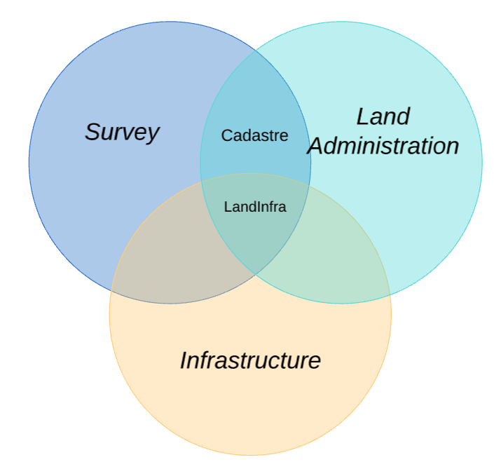
The key point here is that it is expected that Survey concerns are a superset of the survey concerns related to infrastructure. At this stage further engagement with these standards is proposed on the basis of establishing common spatial requirements across a wider set of related domains (key Patterns) - which would provide opportunities to better align these different models.
Note that neither LADM (ISO 19152 - Land Administration Data Model) nor LandInfra Conceptual Model explicitly identify how they relate to the Topology aspects of ISO 19107 - Geometry in a way which provides useful guidance on implementation.
The key conformance class "Geometry Primitives" in this specification is a candidate for a common implementation pattern for 3D Features and topology requirements that may be factored out into a stand-alone specification to assist in future alignment and specification evolution.
| Standard Name | BSi IFC (IFC4 ISO10303) | ISO LADM (ISO19152:2012) | - OGC LandInfra (OGC 15-111r1) | LandXML (landxml.org) | - ICSM ePlan (ICSM ePlan v10) | ISO GML (ISO19136:2020) | OGC CityGML (OGC 20-010) | GeoJSON (IETF RFC 7946) | GeoPackage (OGC 12-128r18) | Geographic Information Spatial Schema (ISO19107:2019) |
|---|---|---|---|---|---|---|---|---|---|---|
|
Primary Users |
BIM & AEC |
Land Admins |
Asset Mgrs, Engineers, Surveyors |
Survey Engineering |
Cadastral Surveyors |
Geographic information modellers |
3D City modellers |
Web developers |
GIS |
Geographic information modellers |
|
Project Gov’ |
Strong |
Strong |
Strong |
Weak |
Medium |
Strong |
Strong |
Strong |
Strong |
Strong |
|
CadastreFeatures |
Partial |
Yes |
Yes |
Yes |
Yes |
Yes* |
No |
No |
Yes? |
No |
|
Cad. FeatSupport |
No |
? |
Yes |
Yes |
Yes |
Yes* |
No |
? |
No |
N/A |
|
Cad.Evidence |
No |
No |
Yes |
Yes |
Yes |
Yes* |
No |
No |
Yes |
No |
|
Evid. Support |
No |
? |
Yes |
Yes |
Yes |
Yes* |
No |
No |
Yes |
N/A |
|
Features (ISO 19109) |
No |
? |
Yes |
Yes |
Yes |
Yes |
Yes |
Yes |
Yes |
Yes |
|
Features Tool Support |
N/A |
? |
Yes (Leica, FME, etc) |
? |
? |
Simple Features only (FME, GDAL) |
? |
Yes (Various web tools) |
Yes (SQLite) |
N/A |
|
Simple Geom |
Yes(ISO10303) |
Yes |
Yes |
Yes |
Yes |
Yes |
Yes |
Yes |
Yes |
Yes |
|
Complex Geom |
Yes(ISO10303) |
Yes |
Yes |
Partial |
Partial |
Yes |
Yes |
No |
Yes |
Yes |
|
Simple Geom Tool Support |
Yes |
Yes (PostGIS, etc.) |
Yes (Leica) |
Yes (12d, FME, etc.) |
Yes (12d, FME, etc.) |
Yes |
Yes |
Yes |
Yes (Most GIS) |
N/A |
|
Complex Geom Sup |
Yes (ISO10303) |
? |
Yes (Leica) |
? |
? |
Yes (FME, GDAL) |
? |
No |
? |
N/A |
|
2D Topology |
Yes(ISO10303) |
? |
Yes |
Yes? |
Yes? |
Yes |
Yes |
No |
Yes |
Yes |
|
3D Topology |
Yes(ISO10303) |
? |
No |
No? |
No? |
Yes |
No |
No |
No |
Yes |
|
2D TopoSupport |
Yes |
? |
Yes (Leica) |
YesLimited |
YesLimited |
Yes (FME) |
Yes (FME) |
N/A |
Yes |
N/A |
|
3D TopoSupport |
Yes |
? |
? |
No |
? |
? |
? |
No |
No |
N/A |
|
Code Lists |
Enums |
Yes * |
Yes * |
Yes |
Yes |
Yes * |
Yes * |
Yes |
Yes * |
Yes |
|
CRS |
Many |
Many |
Many |
Many |
Many |
Many |
Many |
1 |
Many |
Many |
|
Metadata |
Extensive, inconsistent |
ISO 19115 |
ISO 19115 |
Basic |
Basic |
ISO 19115 |
Basic |
STAC, OAPIRec |
ISO 19115 |
N/A |
|
Extensionsallowed |
Yes |
Yes |
No |
Yes |
Yes |
Yes |
Yes |
Yes |
Yes |
N/A |
|
Extension Support |
Medium |
Low |
Low |
Medium |
Low |
Medium |
Medium |
Broad |
Low |
N/A |
4. Conformance
The Domain Model of this specification is composed of a number of Packages which represent Conformance Classes according to the OGC Modular Specification.
This allows for implementers of this specification to describe which particular modules they implement - i.e. that their implementation conforms to.
This specification is primarily a Conceptual Model - meaning that the conformance target of this model is an implementation specification , which is implicitly based on a logical model . These implementation specifications use well known patterns to implement abstract models - which may be viewed as the best options for reusable components of conceptual models , notwithstanding the potential imposition of logical modelling concerns such as metadata aspects of classes.
Thus for example, the key abstract model ISO-19107 (Geometry) may be partially implemented by multiple encodings (e.g. GML and GeoSPARQL). Each encoding using the metamodels of its underlying technology with a logical model of the form imposed be that technology. Thus GML is based on XML schema, which imposes attribute ordering, assumptions that properties are scoped to classes, rigid monomorphic class inheritance and the complexity of either ad-hoc approaches or use of another specification to handle relationships (Xlink) etc. GeoSPARQL uses OWL (Web Ontology Language) with its inherent polymorphism and assumptions. Other encoding technologies such JSON impose their own approaches.
Logical models such as BIM IFC [ref] also illustrate this principle, with the notable example of ifcOWL.
Various modelling languages exist with different advantages and disadvantages. The split between conceptual and logical models in UML is, however, not easily expressed within UML, and inconsistently implemented in practice. On the other hand, the RDF (Resource Descriptor Framework) underpinnings of OWL allow relationships to be readily modelled across different layers of abstraction. In general it is possible to convert models expressed in most other languages into a combination of OWL and other RDF axioms. It then becomes possible to map between related models irrespective of the original modelling language (e.g. ISO using UML, IFC using EXPRESS, LandXML using XSD. )
Another RDF language, SHACL (the Shapes Constraint Language), allows imposition of a logical model naturally onto a largely unconstrained conceptual model. The biggest advantage, however, of using the semantic class model as the modelling paradigm is that it is expressed in a form that allows direct implementation within RDF, in a form that can be validated using SHACL, with a canonical logical model based on the implementation patterns available for components based on established conceptual models. Thus the model can be effectively illustrated and tested by the use of canonical examples . Conversion of these to different implementation models can be undertaken to test aspects of the model, and can be used as conformance test cases for future implementation models based on this model.
The conceptual model is defined as a semantic model using OWL, however UML may be used view this model.
For each logical model implementing this specification one or more implementation encodings may be defined. These encodings are out of scope for this specification, however examples are provided showing how different encodings might realise each of the elements of the conceptual model. Each Conformance Classes in this specification has a SHACL validator for instance data encoded using the canonical logical model , om any valid RDF serialisation encoding option.
Conformance to this specification may therefore be determined by mapping and implementation encodings to the canonical logical model and validating the results using the SHACL validators for instance data.
Profiles of these implementation models may be defined to meet the needs of specific jurisdictions and interoperability with specific systems. Profiles may be described as constraints against specific encodings using the technologies most suitable for the encoding platform.
5. References
The following normative documents contain provisions that, through reference in this text, constitute provisions of this document. For dated references, subsequent amendments to, or revisions of, any of these publications do not apply. For undated references, the latest edition of the normative document referred to applies.
-
This section to be completed before submission as OGC standard . Refer to section 9 "Key Patterns" for discussion of the standard models upon which this model is based.
6. Terms and Definitions
The terms and definitions given in the above references apply in this document, as well as those reproduced or created in this section.
6.1. Conceptual Model
The model that defines the basis for identifying objects and their inherent relationships with other objects.
c.f. "model that defines concepts of a universe of discourse" [ISO 19101]
6.2. Logical Model
Establishing a definition of a logical model , and the tendency of conceptual models to be too closely coupled to logical models is a currently an active area of discussion within the OGC - so this definition is used in the interim for the purposes of this specification
The expression of the sets of properties (attributes and relationships) required to describe features in a conceptual model for the purposes of a specific application. Logical models will typical be constrained around different implementation patterns supported by the meta-models for target encodings.
For example a logical model intended to be encoded as a CSV file will be constrained to a vector of scalar valued attributes (with the potential for constraints around datatype encoding using micro-formats - such as string formats for geometries.)
6.3. Canonical Logical Model
The expression of the conceptual model using well known ("canonical") forms of the underlying abstractions that form the basis of a conceptual model. The canonical logical model is assumed to be "lossless" - that is expressive of the conceptual model within the limitations of the underlying component models. Thus the canonical logical model can act as a proxy for the conceptual model itself in the case where the conceptual schema language is not consistent across the normative definitions of the conceptual model components.
This is a form of conceptual schema ("formal description of a conceptual model [ISO 19101]), however this definition takes into account the possibility that this form is directly implementable as an application schema ("conceptual schema for data required by one or more applications [ISO 19101")
7. Conventions
This document provides a automatically generated view of the normative ICSM Conceptual Model for 3D Cadastral Survey Dataset Submissions specification.
It introduces a number of explanatory mechanisms, notably:
-
Canonical Examples - "well formed" snippets of code that can be directly validated using the canonical logical model SHACL components.
-
Implementation Examples - snippets of code or diagrams that illustrate implementations in some format. These formats may be legacy, alternative standards or potentially future options.
8. Introduction
The 3D Cadastral survey conceptual model specification describes the concepts and fundamental relationships between information elements required to exchange 3D survey data between surveyors and cadastral database systems.
The domain of Cadastral Survey overlaps with other key related domains which have their own special needs and approaches. This model is intended to be reusable by any related domain as part of a more extensive application-specific composite model. As such it defines reusable modules to support partial integration and clearly specifies its dependencies on underlying standards.
Implementations of this conceptual model (i.e. the conformance target ) will be logical models which describe structural implementation patterns and encoding specifications which define exactly how these may be implemented.
The model itself is described using a canonical logical model in a form that best supports modularity as well integration of different levels of abstraction from meta-models through to implementation examples. Please see Annex D for the details and rationale for the specific form of expression. This form of model is not expected to limit implementation options, but does provide an easily-testable "out of the box" encoding option. There is no intention to impose a specific encoding implicit in this choice of modelling expression.
8.1. Model Requirements
The details of the ICSM Conceptual Model for 3D Cadastral Survey Dataset Submissions are driven by an extensive co-design process within the ICSM jurisdictions to define requirements - in the forms of Use Cases and specific pre-conditions (expectations about the data model content) for data exchange for different aspects of cadastral survey data. This work was supported by analysis of available and emerging standards. The separate Use Cases can be combined into an overarching set of requirements, but help reflect the potential for modularity in the model - the potential to implement a subset of total requirements for a given application.
There are a few additional "meta requirements" that dictate the form of the model however:
-
It should be possible to define and express the compatibility of 3D constructs with related application domains
-
3D geom
-
It should be possible to extend the model to support observation of additional aspects of features required for specific applications
-
It should be possible include additional observation methods and result forms in future *
8.2. Standard structure
This specification document provides a series of sections designed to aid in interpreting the form of the model documentation, which is derived directly and automatically from the normative model components.
{statuswarning}
The key sections necessary in order understand to the model itself are:
Implementers may wish first to focus on
Annexes provide details of the established requirements, how these are known to relate to jurisdictional terminology and in detail examples and discussions on methodology.
8.3. Modelling framework
This specification document follows a modular design (based on the OGC Modular Specification policy [MODSPEC]). It comprises several different components in the form of conformance classes , whose requirements are expressed as formal models.
The [MODSPEC] provides for identification of a conformance target that can be tested via an abstract test suite . For a conceptual model the conformance target is an implementation - i.e. a logical model with or without a specific encoding .
It is described using a combination of standard conceptual models for common patterns and the ontology representations of key ISO standards for spatial concepts. This allows for a common and flexible representation of the concepts in a single environment and does not preclude an equivalent UML version of the model.
The Ontology representation provides more natural environment for mapping between conceptual, logical and implementation models, and crucially provides a canonical logical model for a "lossless" data representation that can be used to test implementations of the data model. It is notable that BuildingSmart International BIM/IFC provide ifcOWL with "the same status as the EXPRESS and XSD schemas of IFC".
There is nevertheless potential for a ISO19103 compliant UML model for one or more application schema , each describing a logical model for implementation. Such schemas could be developed in conjunction with a GML schema encoding option if this is deemed to be a viable implementation strategy. Past experience in ISO and OGC in developing such models is that developing a UML model without a testing strategy that includes generation of GM schemas automatically is unlikely to result in a high quality machine-readable version of a model.
Using the canonical logical model approach based on OWL, each conformance class of the model provides a concrete test suite using the SHACL (Shapes Constraint Language) that can be used to validate instance data encoded in RDF. This form of data is used to create illustrative canonical examples and linked to each model elements. These examples however may be expressed in multiple encodings - these, and other examples of current practice are linked as implementation examples , documented with the underlying implementation standard used.
Implementation examples are not normative - they are there to provide illustration of how the model concepts have been implemented in existing or related systems, in order to provide additional clarity of the semantics of the model element for those familiar with these implementations.
In future it would be relatively easy to extend the modelling approach to define one or more normative implementations and mappings to support migration from legacy or related data formats to a normative encoding. This could also be used to define translations between aspects of the model and other platforms - such as BIM/IFC.
8.4. Testing
Testing a conceptual model has traditionally been difficult, and abstract test suites typically make a general statement about implementations including the conceptual elements.
The methodology used to generate this specification has introduced a testing framework with a range of additional testing opportunities:
-
collaborative (co-design with subject matter experts) and formal documentation of requirements as annotations in the modelling language.
-
use of a canonical logical model that can directly express implementation via canonical examples .
-
conversion of model to validation tools to test canonical examples for completeness and correctness (testing the testing…)
-
mapping key concepts to existing and potential future implementation examples.
-
review and mapping of the model to existing regulatory frameworks.
-
cross-referencing terminology to existing usages of similar terminology.
-
assessment of testing coverage of the model against different testing strategies.
8.5. Relationship to other models
This is an informal overview of the relationships between ICSM Conceptual Model for 3D Cadastral Survey Dataset Submissions and related models.
8.5.1. ISO 16739-1:2018 (BIM/IFC)
"IFC is a standardized, digital description of the built asset industry."
The compatibility of the 3D Cadastre model with the extensively used IFC standard has been a prime consideration. The testing framework for the 3D Cadastre includes translation of canonical examples into IFC and CityGML equivalent forms.
Although the scope and requirements for IFC and Cadastre are very different (see Annex ) there are a number of key areas where compatibility can be supported:
-
testing translation of 3D solid geometry elements into IFC "Spaces"
-
use of IFC models to describe Occupation details of surveyed boundaries
-
visualisation of 3D cadastral concepts with the aid of IFC scenes
IFC does not readily support the identified cadastre domain requirements for wider range of observations about survey points and vectors and metadata around survey processes, but this compatibility provides for ready integration of data between design and survey spaces.
Testing will be undertaken over the final stages of the ICSM Conceptual Model for 3D Cadastral Survey Dataset Submissions development project to validate that 3D geometry and topology concepts can be represented in both the proposed profile of ISO 19107 (GeoSPARQL 1.2) as well as IFC through automated translations. A full analysis of the degree of overlap between IFC and this document will be provided after this testing is complete.
8.5.2. CityGML
To be completed. It is noted CityGML does not support survey observation nor explicit topological concerns, however it is expected that the proposed 3D Solid Geometry profile would support the implicit profile of ISO19107 used in CityGML.
More work is required to determine the potential capability, future pathway and relevance of CityJSON.
8.5.3. ISO 19152: "Land Administration Data Model" (LADM)
LADM is an ISO model for Land Administration. LADM encompasses the objects in a Cadastral System - but not the process of survey or the attributes of those objects.
As "LandInfra Standard addresses a subset of LADM", so the cadastral survey domain will overlap through a specific type of land unit. This overlap is best expressed as an equivalence mapping in the conceptual model, since LADM is at a high level of abstraction. The 3D Cadastral logical model and encodings become potential implementations of LADM. [Byron to comment on conformance target of LADM]
8.5.4. LandInfra
Note that the relationship between the 3D Cadastre Model and LandInfra in Figure 2 is highlighted as an area for further exploration and negotiation.
The Land and Infrastructure Conceptual Model is an OGC specification with the declared scope: "land and civil engineering infrastructure facilities".
Currently the Survey component of LandInfra is described as a subset of LandInfra, however it is probably more logical to think of LandInfra using a relevant subset of a Cadastral Model, since the infrastructure is just one application of survey and cadastre.
A discussion with the LandInfra authors regarding possible optimal refactoring of the LandInfra standard in a new version is proposed. Such a revision would hopefully adopt a more flexible, extensible and convenient approach to the implementation of ISO 19156 Observations and Measurements as proposed in this standard, and simplify its structure by removing much of the comparison with other approaches from the main specification.
A corollary of this is the relationship of LandInfra to specific domain models such as Pipeline ML, MUDDI etc - ideally a refactor of LandInfra to support linkages to specific domain models can be achieved at the same time as abstracting cadastral and survey elements into more easily reusable component models.
9. Key Patterns
We based this conceptual model for the ICSM Conceptual Model for 3D Cadastral Survey Dataset Submissions on a set of well-known conceptual models for which implementation patterns are available. The abstractions of these patterns provide a basis for consistency of approach across a range of similar requirements with the assurance of a direct pathway to at least one available implementation approach (and often several alternatives). They also establish patterns to extend the model and address specific implementation requirements.
Each pattern is described below to aid in interpreting the details of the model in the normative sections.
9.1. Pattern - Modular Components
Context - Consistent use of loosely coupled modular components creates a system that is easy to implement, use, maintain and extend.
Consider - A well-governed model should include reusable mechanisms that simplify and extend functionality across a wide range of implementations. Vocabularies and Codelist is one example of shared components.
Problem - The lack of shared components can lead to diverse and incompatible solutions. A component is just a generic term for any predefined object used across multiple applications. For components to be reusable, they must be standardised. This standardisation ensures that each component reliably delivers regardless of the context in which it is used. Think of modular components as Legos: interchangeable building blocks you can assemble into pages.
Loose coupling and high cohesion Monolithic design with high dependency between components often produces heavyweight solutions suited to a few environments. Cohesion often refers to how the elements of a module belong together. High cohesion prevents the propagation of errors distributed across the model.
Solution - Provide Modular components to create a flexible design with reusable components across many environments. Apply loose coupling and high cohesion to ensure the components are reusable by minimising the number of connections and dependencies between components.
Good modular design requires a sound governance regime. Many models fail over time due to the lack of proper governance of the model and its modules. Many Standards Development Organisations (SDOs) exist with the express purpose to maintain such standards, e.g. OGC, ISO, BSI. Other organisations exist that participate at a different level, such as maintaining localised code lists. These may be cross-government organisations such as ICSM or professional bodies such as FIG. Some organisations fill multiple roles. Standards maintenance is not an optional task - it will fall on someone. By default, it is the creator of the standard. Ignoring governance issues creates significant risks to a standard’s sustainability and its ability to provide the desired interoperability benefits.
To make components modular:
-
Standardised design: Structure and interface is predetermined and doesn’t vary by implementation.
-
Standardised, centralised code: Unique code should not be needed each time you reuse the component.
-
Controlled via system logic: Predefined behaviour should occur based on system rules, not content author discretion.
-
Customisable options: Localised rules can provide for functional options controllable via metadata or other configuration settings.
Use this pattern to achieve interoperability of components across the related applications in the domains. Make components available through reusable software libraries to ease model implementation across multiple solutions. Make available tools to validate that solutions developed produce conformant results.
Ensure that a stable body exists to govern each and any solution component. Where such a body does not exist, account for the cost and overhead of creating one. The rules of governance and methods by which one can participate should be clear and accessible to those using the standard.
9.2. Pattern - Conceptual Model
Context - A robust conceptual model, based on real-world use cases, is required to identify objects and their inherent relationships with other objects within a universe of discourse.
Consider - While Modular components is essential across all whole a data model, the whole must be expressed as a Conceptual Model
Problem - Within any business process, there are many ways to conceptualise the entities and relationships that comprise a process. The absence of a common conceptual model leads to a proliferation of ad-hoc approaches to common problems.
Solution - Develop a conceptual model through a collaborative and iterative process based on use cases derived from domain experts. Iteratively test, validate and improve the developing model with stakeholders. Through this robust process, determine the model parts and their relationships.
The resulting Conceptual Data Model is a diagram identifying the business concepts (entities) and the relationships between these concepts to gain, reflect, and document understanding of the organisation’s business, from a data perspective.
"It shows how the business world sees information. It suppresses non-critical details in order to emphasise business rules and user objects. It typically includes only significant entities which have business meaning, along with their relationships."
Entrust governance of this model to a Standards Development Organisation at as high a level as possible.
Consider next -
-
Ontological Modelling to formalise the structure of the model.
-
Vocabularies and Code-list to standardise teminologies.
-
Canonical Logical Model
-
Domain Compatibility
9.3. Pattern - Ontological Modelling
Context - Communicating the nature of a conceptual model in a precise manner requires the use of formal language. Of the available standard approaches, an Ontological approach provides the most flexibility.
Consider - This pattern provides a useful method of formally describing a Conceptual Model
Problem - When building a conceptual data model where the choice of implementation schemas and encodings is undecided, the modelling language needs to provide as much flexibility as possible to support multiple options while preserving commonality.
Many languages exist to describe data models. The Unified Modeling Language (UML) is one common language used by OGC and ISO TC211. EXPRESS is another commonly used in the BIM community. However, we have chosen an Ontological approach using the Web Ontology Language (OWL) for this project. An Ontology representation provides a more natural environment for mapping between conceptual, logical and implementation models and crucially provides a canonical logical model for a "lossless" data representation to test implementations of the data model. OWL provides a higher level of abstraction and openness than other options. Thus, it is easier to derive other models like UML and EXPRESS from OWL than the reverse. Furthermore, the native output of OWL being RDF (a linked data format) provides additional advantages. (See https://www.w3.org/RDF/advantages.html).
Solution - Use the ontological modelling language Web Ontology Language (OWL) to build the data model. OWL provides a high level of abstraction and openness, allowing for the derivation of implementation models.
Consider next -
-
Linked data Support
-
Flexible Domains of interoperability
Links -
-
RDF discussion - https://www.w3.org/RDF/advantages.html
9.4. Pattern - Feature / Geometry Distinction
Context - In a cadastral dataset, a feature, such as a parcel, may be spatially described in many ways. It may have point descriptions, 2D descriptions, volumetric descriptions, and others.
Problem - The distinction between a Feature and its geometry attribute(s) is a key pattern for describing the "real world" flexibly. Whilst early GIS applications may have tended to attach attributes to a geometry object this leads to ad-hoc approaches to unambiguously identifying the real-world features. Each application chose a different name and form for the feature identifier - illustrating the problems with modelling via logical models without an underlying conceptual model.
Solution - Using the General Feature Model defined in ISO 19109, Feature Type models are used to classify the representations of real-world things. Inherent in this is the identification of such features, which implicitly enables the declaration of relationships between instances of these types. Under this model, features may have an arbitrary number of attributes describing spatial aspects (geometries) or topologies. In practice, implementations are often optimised to support a specific form of spatial representation within the context of the application. Thus in 2D GIS systems, sets of cadastral parcels may be described by a series of polygons with a common set of business rules regarding the assumed vertical datum, coordinate systems, level of precisions etc. This doesn’t preclude other forms of representation, but logical data models are constrained and simplified by these assumptions of homogeneity.
When features are indistinct from their geometry in the data model, it is difficult to record more than one spatial definition for that feature. Therefore, neither the conceptual nor canonical logic constrain the range or number of possible geometry representations of any given feature in this specification.
However, any logical model for implementation may choose to implement different sets provided they conform to cardinality constraints defined in the conceptual model.
9.5. Pattern - Observations Model
Context - A core element required by this data model is to attach metadata about Observations to attributes of features.
Problem - A common challenge in data modelling is the attachment of observation metadata to attributes of features. A range of different logical models are often used, including definitions of complex datatypes or multiple related attributes. Specification notes may define the conceptual relationship between attributes. Alternative methods use naming conventions (area, area_units, area_measurement_process, area_previous etc ad infinitum ).
Solution - The Observations pattern is a well established conceptual model (c.f. ISO 19156) for describing metadata about the process of observation of the value of a property of a feature.
The benefit of this pattern is that it provides great flexibility to:
-
add observations about any aspect of any feature type using the same encoding syntax
-
provide explicit information about the time of observations in a standard way
-
be extended to provide richer information models about processes and equipment as required by localised implementations.
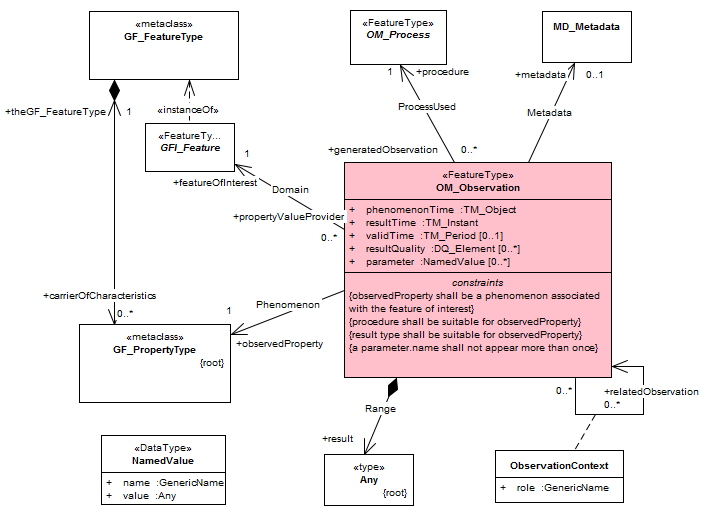
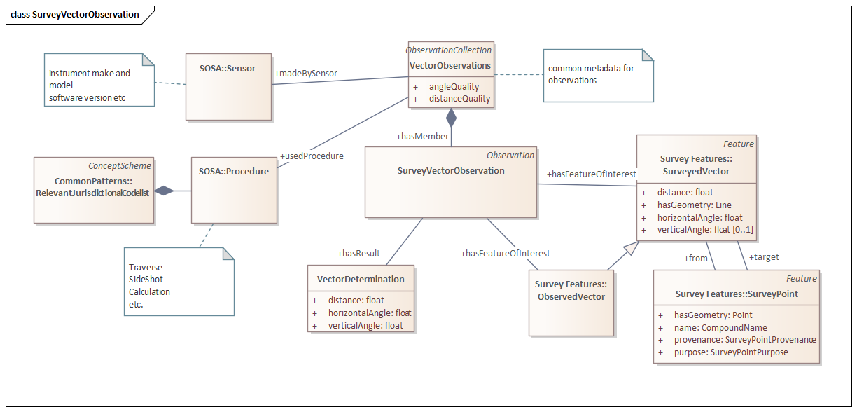
A Canonical Logical Model for ISO 19156 is available in the OWL language: SOSA (Sensor, Observation, Sample and Actuator). This forms part of a larger model that supports description of observation equipment, sampling strategies etc.
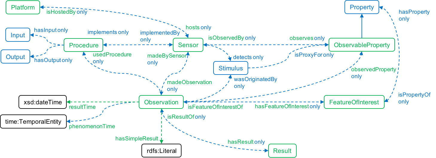
Note that the SOSA logical model includes some additional conceptual elements such as the "Sensor" and provides standardised ways of describing what is observed, when (of observation and the phenomenon being observed). Also, note that the Procedure is modelled in the abstract only - and each implementation will need to determine an appropriate logical model for this component.
Using the Observations pattern allows metadata to be attached to changes in the state of any feature’s property. Furthermore, this specification supports the inclusion of additional observation types not defined without the need to change underlying logical models (where the meta-model for the logical model does not define an inflexible schema). Thus, this pattern accommodates other details such as the addition of point-cloud observations, photographs of survey monuments, the locus of mobile sensor platforms, by new types of observations and the specification of encoding for different observation result data types. There are multiple ways of specifying properties, however the most powerful and unambiguous option is to specify the logical properties of the FeatureOfInterest . A profile of SOSA to make this choice of implementation pattern is proposed and included as a module.
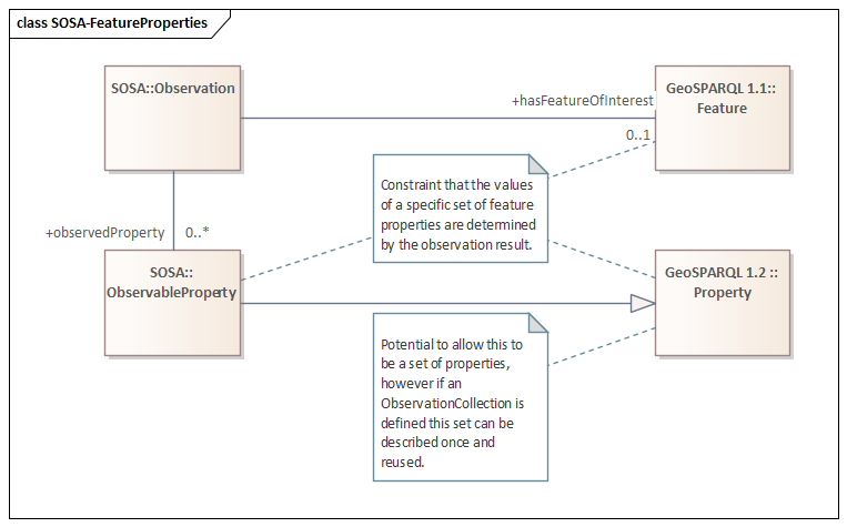
The ObservationsCollections sub-pattern introduced in updates to SOSA and Observations and Measurements Version 3 working draft provides for common metadata to be shared across multiple Observations in a Collection.
9.6. Pattern - Provenance Model
Context - The nature of this data model requires a well-structured way to capture information about processes and associated times and dates
Consider - One aspect of implementing the Flexible Domains of interoperability pattern includes the need to support various ways organisations and jurisdictions may capture process and date information. The Vocabularies and Codelist pattern covers aspects of this issue but does not address the need for a standard data model for this information.
Problem - The data model must address complex chains of activities. Many of these may vary in polymorphic ways across jurisdictions. A robust model that accommodates this is required.
Solution - The PROV-O Ontology provides a common pattern related to process and times. This standard provides metadata about processes and provenance of information and is formally aligned to the Observation pattern. Together, these patterns form the basis of both the conceptual and canonical logical models.

The provenance pattern provides a well-known pattern for capturing metadata for relatively complex chains of events. For example, implementations can choose the types of activities, entities and agents, then include any business rules and apply a single logical model to these chains. Or choose a restricted profile based on a fixed set of activities as a custom logical model (i.e. a pre-defined set of date elements in a simplified schema.)
Consider next -
-
The Observations pattern is formally aligned to a more general provenance model using the PROV-O Ontology.
9.7. Pattern - Canonical Logical Model
Context - To implement a Conceptual Model in a consistent interoperable fashion, one needs standardised descriptions of the attributes and relationships of the objects described in the model.
Consider - This pattern expresses and builds upon the Conceptual Model using Ontological Modelling to provide a consistent approach to implementations.
Problem - The proliferation of ad-hoc approaches to implementing a conceptual model leads to incompatible non-interoperable implementations.
Solution - Express the conceptual model using well known ("canonical") forms of the underlying abstractions that form the basis of a conceptual model. The canonical logical model is assumed to be "lossless" - expressive of the conceptual model within the limitations of the underlying component models. Thus the Canonical Logical Model can act as a proxy for the Conceptual Model itself in the case where the conceptual schema language is not consistent across the normative definitions of the conceptual model components. The Canonical Logical Model is a form of conceptual schema ("formal description of a conceptual model [ISO 19101]). However, this definition takes into account the possibility that this form is directly implementable as an application schema ("conceptual schema for data required by one or more applications [ISO 19101]")
9.8. Pattern - Flexible Domains of interoperability
Context - Within a domain community, different local requirements may lead to variations of implementation of a data model. To provide the desired interoperability between organisations within a knowledge domain, a data model needs to offer enough flexibility and extensibility to support subtle differing organisational requirements.
Consider - Use of this pattern allows for the adaptation of the Conceptual Model and Canonical Logical Model to fit a particular implementor community’s unique business requirements.
Problem - Subtle differences always exist between different organisations' data and processes in performing the same service. Too rigid a data model leads to localised workarounds that undermine desired interoperability
Rigid data models provide interoperability between the organisations that use them. But workarounds are commonly implemented when an organisation’s unique business requirements do not fully fit the data model. These workarounds may inhibit the desired interoperability. Therefore, provision of some flexibility and extensibility to the data model is often required. However, too much flexibility may lead to unmanageable diversity of implementation that also inhibits interoperability.
Solution - Designed the data model with enough flexibility to support the differences in requirements that various organisations in the domain may have. Ensure the existence of governance regimes to maintain and oversee these modifications. Carefully considered each variation to keep these limited in number and the model as simple as possible. The proliferation of customisations inhibits interoperability and vendors' ability to implement and support the model.
Consider next -
-
Profiles
-
Vocabularies and Codelist
9.9. Pattern - Vocabularies and Codelist
Context - As standards are built upon agreed understandings of terminology, standardised vocabularies are necessary for creating an effective data model. However, some local vocabularies will likely persist and need to be managed and supported.
Problem - The lack of common understanding of terminologies is the first problem encountered when creating a standardised data model. This may not be apparent until late in the process. Misunderstandings can badly affect the utility of chosen standards. Furthermore, due to internal business reasons, different localities and organisations will still wish to refer to some objects, attributes, and relations using other terms and possible definitions.
Solution - The foundation of effective data modelling is to establish common vocabularies to ensure participants agree upon the usage of terms used in the model. This vocabulary will grow as work progresses and will require good governance. To be most effective, store this common vocabulary in a web-accessible registry.
In addition, localised terminologies may be required to support localised business requirements. A key implementation pattern to this purpose is using a code list specific to a specific application domain, such as the regulatory environment of any particular jurisdiction. This pattern could be described as either a simple scalar value or a meta-model such as a CodeList (ISO 19103) or ConceptScheme (SKOS). Declaring distinct conceptual types for each code list, as a subtype of a common meta-model (a SKOS Concept Scheme in the canonical logical model), allows implementations of these lists to declare the type of value they represent and (some types of) implementation models to self-document the specific type of value required in properties that references whilst allowing for simple implementation using standard patterns for values from such lists. It also clearly identifies the use of a consistent pattern each time required, for example, the set of code lists needed to configure an implementation for a given jurisdiction.
Consider next -
-
Linked Data
-
Domains of interoperability
-
Modular Components
9.10. Pattern - Profiles
Context - To ease the ability of implementors to support the data model, a data model should support the customisations of the model to suit a community’s variation of required model objects.
Problem - A particular group of implementors may find a data model challenging to use because the choice of model objects is more extensive than their needs. Or they may discover missing from the otherwise well-suited model some things they need. Inconsistent, incompatible implementations may result.
To provide for the needs of various organisations and support the greatest interoperability, a data model may need to include for a particular implementation more objects, attributes and relations than required by a specific group of implementors. Conversely, another group may wish to extend the model with some objects, attributes, and relations not present. Profiles provide a mechanism to limit and/or extend a data model to support local requirements.
Solution - Profiles are a well-established pattern to constrain the usage of a specification within a narrower scope and with greater consistency where the original specification does not mandate specific implementations. Conformance to a profile implies conformance to the profiled specification. Profiles provide a key mechanism to define a "domain of interoperability" encompassing as many aspects as required. For example, in the case of data models, profiles allow ready identification and declaration of conformance to areas of commonality and interoperability between complex specifications.
Geometry profiles - An example of the profile pattern that will be familiar to the geospatial standards community is the definition of a profile of the complex and broadly scoped abstract model of geometry and topology defined by ISO 19107. In typical GIS applications, the Simple Features Profile limits data types to simple points, lines and polygons widely supported by such systems and encoding formats. Thus, the extensive and theoretical scope of ISO 19107 (see Figure 1 from ISO 19107) is significantly reduced in a consistent way that can easily be implemented and tested. Furthermore, it provides interoperability within the applicable scope, ensuring that implementations can also interoperate with more complete implementations of the abstract model since the underlying abstract specification defines the common elements.
Many informal profiles - i.e. text in specifications, identify the additional constraints imposed - such as GeoJSON and CityGML, state (without direct reference to ISO19107) the subset of ISO19107 geometry types supported. Other profiles are formalised but may be constrained to specific implementations like the Simple Features SQL standard.
The formalised profile approach is taken for the ICSM Conceptual Model for 3D Cadastral Survey Dataset Submissions, with the definition of a candidate profile of ISO 19107 for the minimal set of geometric and topological elements required for cadastral applications. This profile is a superset of an equivalent profile that could be abstracted from the implementation patterns supported in CityGML and IFC and the Simple Features Profile.
Logical profiles - In addition to restrictions on conceptual scope, profiles may also determine specific sets of attributes to be attached to a given conceptual class - such as expressed in UML Application Schema class models, XML-, or JSON- schema, SHACL "Shapes".
SHACL is used to describe the canonical logical model for the ICSM Conceptual Model for 3D Cadastral Survey Dataset Submissions using constraints against general-purpose conceptual models. These can be further extended using the same mechanisms to define localised profiles to meet implementation requirements.
9.11. Pattern - Quality Model
Context - In most any information system, data quality is an important dimension to record. When recording Cadastral Survey data, it is a central concern.
Consider - Provenance and Observations require the support of a model to record the qualitative dimensions of the data. The use of Vocabularies and Codelist with this pattern supports Flexible Domains of interoperability
Problem - The value of a survey rests on understanding the accuracy of the measurements. Different jurisdictions will have different rules and methods regarding recording the quality of the measurements and observations.
Solution - Inclusion of the Quality Model provided by ISO19157 allows for a standardised approach to record quality measures such as precision and accuracy. This data quality model accommodates the differing existing quality metrics and rules implemented by the jurisdictions.
Links - ISO 19157:2013 Geographic information — Data quality - https://www.iso.org/standard/32575.html
9.12. Pattern - 3D Solid Geometry
Context - To support the capture of 3D cadastral objects, the data model must support the definition of 3D solid geometries.
Problem - Without the ability to describe cadastral information as volumetric solids, the ability to submit 3D cadastral information is limited as it is impossible to test whether the solids are watertight or validate spatial relationships between cadastral parcels.
2D cadastre parcels only require definition in two directions, East (X) and North (Y). Whereas in the 3D space, spatial units defining the extent of a cadastral parcel require definition in all directions, X, Y and height. Within the computer modelling domain, the main representations used for the representation of solids, spatial units constrained in all directions, include:
-
Cell decomposition - division of space, or a cadastral feature, into a set of elements, typically voxels;
-
General sweeping - the representation of objects in terms of 2D shapes extruded along general curves, i.e., constructive solid geometry;
-
Set theoretic - a set of primitive shapes or (parametric) surfaces (more correctly half planes) that when combined using Boolean operators form a solid; and
-
Boundary Representation - a collection of surface elements that form the skin of a solid.
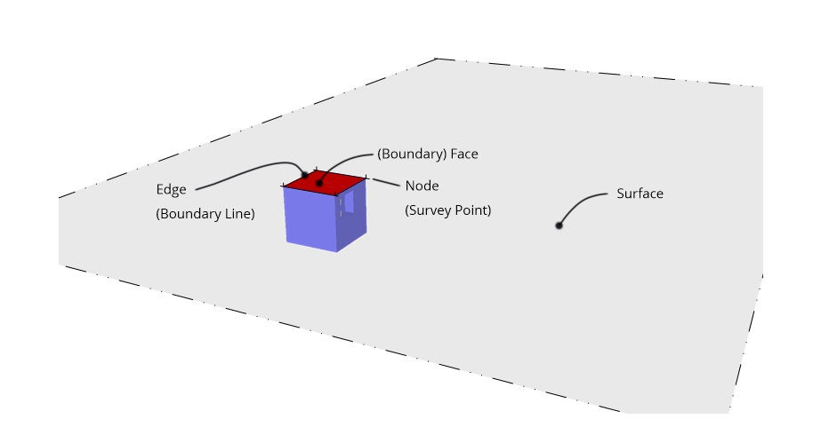
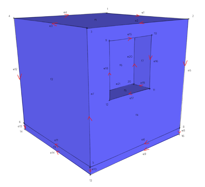
ISO 19107:2019 adopted the Boundary Representation (B-Rep) to describe vector data. The skin is composed of a set of adjacent bounded elements called faces; cadastral boundary faces in this context, which defines the object’s shell. Faces are bounded by a set of edges, or boundary lines, which are curves lying on the surfaces of the faces intersecting the edges. The points where several faces meet are called vertices and represent survey points generally. When physical markers are placed on the ground as part of a cadastral survey, they represent Boundary Marks. The data structure can be divided into two primary groups: one responsible for defining the object’s structure (the topology) and the form or shape of the object (the geometry).
Solution - Represent spatial properties of all 3D CSDM feature types using the geometry classes defined in ISO 19107. Depending on the feature type, spatial representations can have 0-, 1-, 2-, or 3-dimensional extents. All new 3D CSDM geometries are expected to use 3D coordinate values. However, it is expected the 3D CSDM will also manage that legacy 2D data.
Besides the primitive geometries, points, curves, surfaces, and solids, the 3D CSDM allows aggregations of geometries like spatial aggregates (MultiPoint, MultiCurve, MultiSurface, MultiSolid) and composites (CompositeCurve, CompositeSurface, CompositeSolid).
The 3D CSDM Conceptual Model does not restrict the usage of specific geometry types as defined in ISO 19107. For example, 3D surfaces could be represented in a dataset using 3D polygons or 3D meshes such as triangulated irregular networks (TINS) or by non-uniform rational B-spline surfaces (NURBS). However, an encoding or a jurisdictional profile may restrict the usage of geometry types. For example, curved lines like B-splines or clothoids, or curved surfaces like NURBS could be disallowed by explicitly defining null encodings for these concepts in the encoding specification.
Require non-2-manifold geometry (unbounded volumes) to represent conventional 2D parcels that are unbounded in the Z-axis (height). ISO 19152 refers to these representations as Liminal Spatial Units and represents them using a 2D boundary face string (on the map datum) and vertical boundary faces. In effect, fake edges are required at some arbitrary elevation to allow various spatial operations to be performed, for example, it is not possible to determine the orientation of a face extending to +/- infinity in the Z axis.
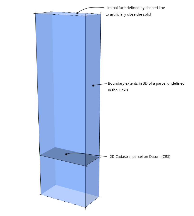
In many instances, a cadastral parcel’s upper and lower height limits with respect to a specific datum are known. The upper and lower height limits slice the vertical faces of the unbounded cadastral parcel to create a polygonal slice. Alternatively, a polygonal slice can be considered a type of extrusion of the 2D cadastral parcel along the Z (height) axis with specified limits.
9.13. Pattern - Topology of 3D Solids
Context - The recording and testing of the spatial relationships between features in the cadastre (topology) is an essential aspect of the cadastre.
Problem - The value of the cadastre diminishes if the spatial relationships between cadastral objects cannot be retrieved and tested.
Solution - Record geometry and features once, when required elsewhere, reference them via unique identifiers. Favour encodings that support the inclusion of as many rules as possible.
From a cadastral survey perspective, topology provides two main functions. First is validating the data according to specific rules, e.g., no overlaps or gaps between primary parcels. Second is the ability to identify and manage shared boundaries and other geometric relationships, e.g., in New Zealand, a Unit Title represents a stratum estate that lies within the base land (subdivided parcel) and is disjoint from the Common Property held by the Body Corporate. Satisfaction of this second requirement assists the implementation of the first because topological models allow geometries to be captured once and referenced many times, significantly reducing data volumes and enhancing dataset integrity results.
Adopting the principles of topology also enables rapid spatial data retrieval, enhanced spatial analysis, and enforcement of data integrity rules.
Delegation of the enforcement of some topological rules to the application domain may be necessary. Indeed, it is possible, and even common, to delegate all topological concerns to the application. However, embedding topology in the data increases the interoperability of the data by reducing the reliance on particular software components, and also preserves the benefits of dataset integrity and reduced file size.
Ideally, the topological graph should be bidirectional, i.e., capable of being navigated up and down the graph. It is common to from higher dimension geometries from sets of lower geometries, a boundary line (a 1D geometry) is defined by a set of 2 or more survey points (0D geometries). Construction of geometries in this manner implicitly informs the topology of a spatial unit. However, topology in this sense only allows one-way navigation of the topology graph. Therefore, functions may be required to generate the necessary topology to address specific spatial queries, i.e., which survey points define the solid(s) describing this/these cadastral parcel(s).
This approach reflects the general approach taken by cadastral surveyors when defining cadastral parcel boundaries. Original, reliable monumentation (survey points) defines a cadastral boundary’s location. A closed set of cadastral boundary lines defines the cadastral parcel, or a cadastral parcel face in the 3D space, …
Topological relations between geometries can be established by sharing geometries (typically parts of the boundary) between different geometric objects. For example, the face between two adjacent 3D cadastral parcels should only be represented by a single geometry (a face ) and referenced by all features or more complex geometries defined or bounded by the face. Thus, redundancy can be avoided, and explicit topological relations between parts, maintained.
An ideal representation geometry and topology are kept separate, allowing greater flexibility but at the risk of ambiguity when created with conflicting information.
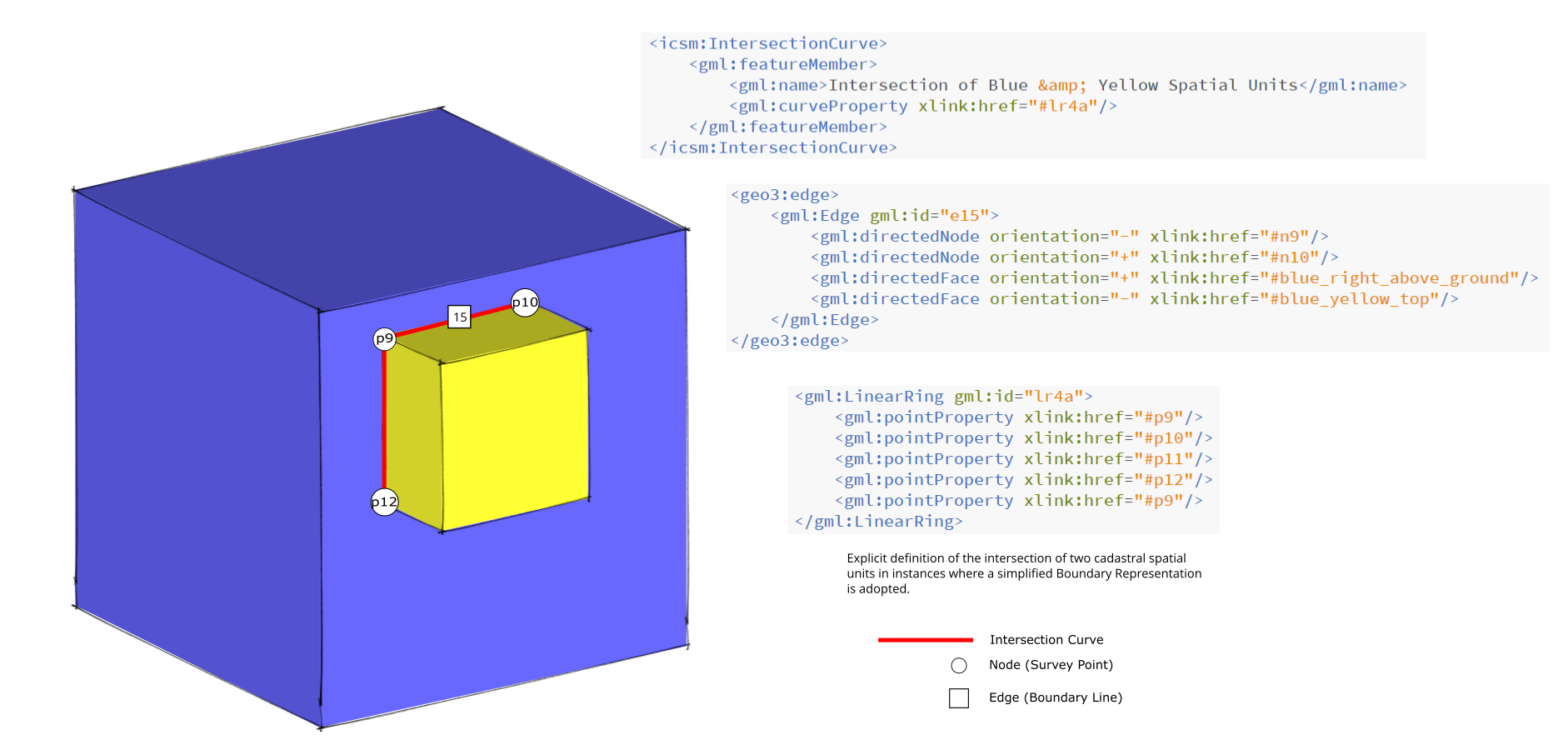
If cadastral spatial unit geometric representation implements a Boundary Representation approach strictly, then in instances where two or more spatial units intersect, e.g., an easement passing through a cadastral parcel. Each spatial unit is split into discrete solids. (The cadastral unit would split - the portion of the cadastral unit outside the easement and the portion inside the easement. The easement would be split at the cadastral parcel boundaries.) These would then aggregate to form each specific spatial unit. The easement portion inside the cadastral parcel, being common to the cadastral parcel and the easement, is only created once but referenced in the definition of each spatial unit. All intersections between the cadastral unit and the easement are explicitly defined in this approach. A simplified approach might model the cadastral parcel and the easement independently of each other. There is no explicit definition of the relationship between the two spatial units in this instance. If such an approach is adopted, it is recommended that an intersection curve be defined to describe where the two solids meet explicitly.
Consider next -
-
Including Linked Data support in the implementation model and encodings can reduce duplication of features and their geometry .
9.14. Pattern - Domain Compatibility
Context - To ease implementation and uptake, new systems should be as compatible with existing practices within a domain and jurisdiction as possible. Include contributions from existing solutions providers in design.
Consider - Reusable Modular components should consider the ability of existing solution providers and practitioners to implement and use the model designed.
Problem - New systems often engender unfamiliar ways of doing things, making the solution hard to implement and use. Solutions that are alien to the business of the existing software providers are unlikely to be implemented and supported. If the current technical support community finds a model challenging to implement is unlikely to gain traction.
Sometimes change is necessary to overcome poorly designed and implemented previous solutions. Other changes may offer benefits when modelling the data, but they are not worth the pain incurred in implementation. Getting the balance right is critical to a good model. Relational database designers call this process "denormalisation".
Solution - Use cases derived from the existing community of professionals should provide the foundation for creating a solution as familiar as possible to potential implementors and users. When vocabularies need to be standardised in the model, ensure that local terms may be substituted. Allow polymorphic objects to address situations where particular rules and types apply to entities only in certain jurisdictions.
Engagement with the relevant software vendor community is an essential part of this process. Through this engagement, the supporting software community gains confidence that they can implement the model cost-effectively and usable. We demonstrate the ability to implement this model through good documentation and provide candidate encodings for the most complex concepts expressed in familiar standard encodings. Parts of this model will be difficult, or even impossible, to implement in much of the current traditional software and systems.
Consider next -
-
Use Vocabularies and Codelist to preserve the terminologies used by a community.
-
Apply the Flexible Domains of interoperability pattern to address object type variations and rules.
9.15. Pattern - Linked Data Support
Context - To unambiguously share information across and between systems, it is helpful that the model allows the expression of the data according to linked data principles.
Consider - The natural output of an Ontological model is
Problem - There is a great need to share cadastral survey data across many disciplines. Siloed systems where clear identity is hard to determine and maintain reduce the usability and utility of these data.
Solution - Follow the four principles of Linked Data in the model design and implementation -
-
Use URIs as names for things.
-
Use HTTP URIs so that people can look up these names
-
When someone looks up a URI, provide useful information using the standards (RDF, SPARQL)
-
Include links to other URIs so that they can discover more things
To sum it up, Linked Data breaks down the information silos between various organisations and brings down the fences between multiple formats. Furthermore, the Linked Data principles facilitate the extension of the data models and allow easy updates. As a result, data integration and browsing through complex data become more manageable and efficient.
The use of OWL in creating this model provides a native ability to leverage the benefits of Linked Data and create implementations encodings such as TTL and JSON-LD, using the Resource Descriptor Framework (RDF) model. The use of such encodings, while not currently common for cadastre, is growing in multiple related fields. RDF encodes multiple OGC and ISO TC 211 standards and the notable example of ifcOWL.
Furthermore, the language of Linked Data, RDF, relies on a triple store model of subject, object, predicate. The unambiguous recording of the predicate provides the most distinctive feature of RDF and Linked Data. The predicate allows the meaning of the relationship between objects to be explicitly recorded and transmitted in the data, greatly enhancing interoperability.
Consider next -
-
Implement Vocabularies and Codelist using these Linked Data principles.
Links -
10. Domain Model
10.2. Class Hierarchy
+ expand all, click '+' to expand individually
-
Class defined in 3dCadastre Model
-
-
-
Cadastral Parcel (defined elsewhere)
-
Parcel Aggregate (defined elsewhere)
-
-
-
-
-
Cadastral Survey Dataset (defined elsewhere)
-
10.3. Conformance Class: 3D Geometry and Topology Basic Profile
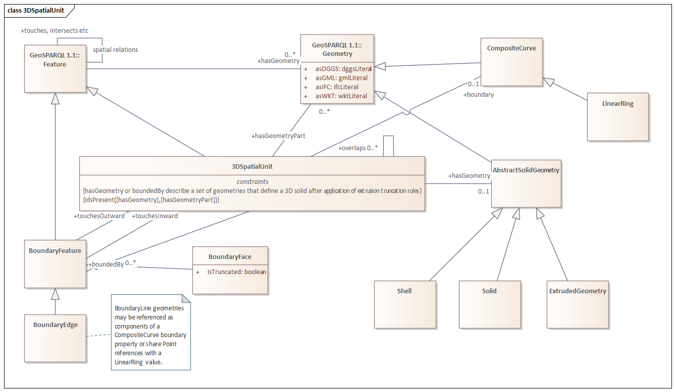
10.3.1. Class: 3D Spatial Unit
A general 3D spatial unit is an abstract represented a closed solid or multi-solid or other valid geometry from which a solid can be derived.
Subclass of
-
Feature (From GeoSPARQL Vocabulary )
Properties
| Property | Description | Cardinality | Range | Use Case Requirement |
|---|---|---|---|---|
|
from 3D Spatial Unit |
overlaps |
[0..*] |
||
|
from 3D Spatial Unit, Feature |
Constrain geometry to a form that supports calculation of interior and surface domains. hasGeometry property inherited from geo:Feature |
[0..*] |
||
|
from 3D Spatial Unit |
boundedBy |
[0..*] |
||
|
from 3D Spatial Unit |
A component geometry part potentially containing references to reusable used in the main geometry representation |
[0..*] |
10.3.2. Class: Boundary Edge
A Boundary Line is a feature whose geometry is a connected set of lines representing the common part of two polygons share this set of oriented lines. As a feature it can participate in topological relationships between features that may, or may not, have planar geometry representations, and observations about the nature of the boundary can be made. The inner and outer features may be swapped by inverting the orientation of the geometry primitive, thus a single orientable boundary line may be used to partially define boundaries of both touching features. An oriented linear ring geometry representation for the planar extend of a bounded feature may be calculated from the geometries of the set of boundary features, using the inward or outward topology to adjust orientation accoridingly.
Subclass of
-
BoundaryFeature (From 3D Geometry and Topology Basic Profile )
Properties
| Property | Description | Cardinality | Range | Use Case Requirement |
|---|---|---|---|---|
|
from Feature |
hasGeometry property inherited from geo:Feature |
[0..*] |
||
|
from Boundary Edge |
nodeFrom |
[1] |
||
|
from Boundary Edge |
equivalent to a GML directedNode with orientation "-" |
[1] |
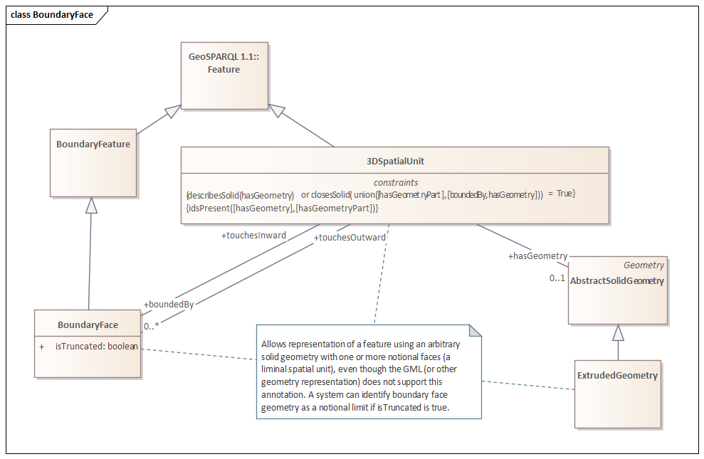
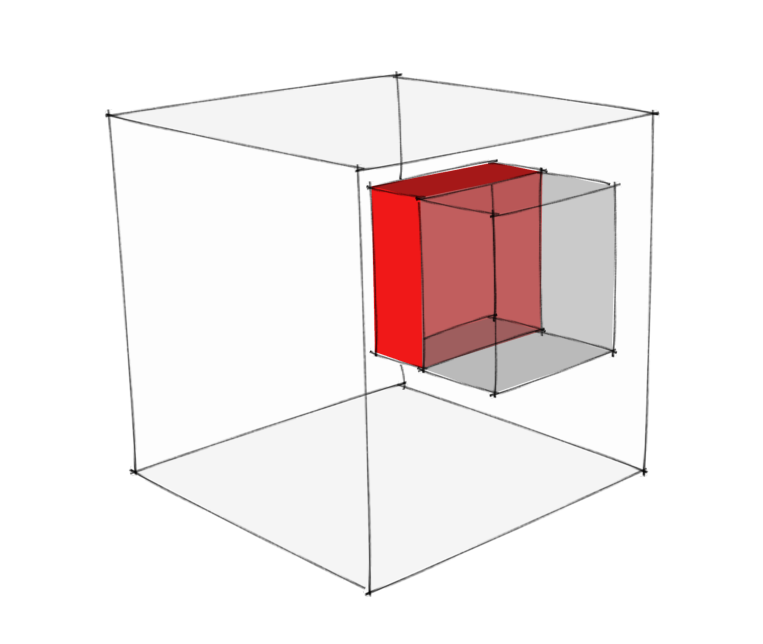
10.3.3. Class: Boundary Face
A Boundary Face is a feature whose geometry is the orientable (possibly composite) surface where two solids touch. As a feature it can participate in topological relationships between features that may, or may not, have solid geometry representations, and observations about the nature of the face can be made. The inner and outer features may be swapped by inverting the orientation of the geometry primitive, thus a single orientable boundary face may be used to define boundary faces of both touching features. The shell of a feature may be computed from the set of faces defining boundaries.
Subclass of
-
BoundaryFeature (From 3D Geometry and Topology Basic Profile )
Images
|
Format |
|

|
Format |
|
|
Format |
|
Canonical Examples
|
|
|
10.3.4. Class: Boundary Node
A Boundary Node is a feature whose geometry is a single Point representing the touching of two or more features at a single node. As a feature it can participate in topological relationships between features that may, or may not, have planar geometry representations.
|
Note
|
Statement required regarding the topology here - are we interest in the touching features or the edges of those features - those edges may not be separately represented so it should be the bounded features. If so - how does one identify the edges when building a topology? |
10.3.5. Class: BoundaryFeature
A Boundary Feature is a topological concept - an object relates to a specific geometry type and adds information about the orientation of the geometry relative to topologically connected features. Note that a Featuredefined without specifiying the underlying geometry if required, allowing for example the geometry to be measured or calculated by operations on the geometries of related features.
Subclass of
-
Feature (From GeoSPARQL Vocabulary )
Requirements
10.3.6. Class: AbstractSolidGeometry
An Abstract Solid Geometry is...
Subclass of
-
Geometry (From GeoSPARQL Vocabulary )
10.4. Conformance Class: Cadastral Parcel
10.4.1. Class: Estate
A set of real property rights that can be held by a legal entity.
Subclass of
-
Interest In Land (From Cadastral Parcel )
Canonical Examples
|
Description |
An estate is not modelled explicitly - it is simply a reference to an external system - for example a persistent IRI or local system identifier. Implementing profiles may define addtional metadata for such references if needed. |
|
|
|
10.4.2. Class: Estate Parcel
The spatial extent of an Estate. It may consist of one or more cadastral parcels.
Subclass of
-
Parcel Aggregate (From Cadastral Parcel )
Properties
| Property | Description | Cardinality | Range | Use Case Requirement |
|---|---|---|---|---|
|
from 3D Spatial Unit |
overlaps |
[0..*] |
||
|
from 3D Spatial Unit, Feature |
Constrain geometry to a form that supports calculation of interior and surface domains. hasGeometry property inherited from geo:Feature |
[0..*] |
||
|
from 3D Spatial Unit |
boundedBy |
[0..*] |
||
|
from 3D Spatial Unit |
A component geometry part potentially containing references to reusable used in the main geometry representation |
[0..*] |
||
|
from Estate Parcel |
[1..*] |
|||
|
from Estate Parcel |
[0..*] |
Canonical Examples
|
|
10.4.3. Class: Interest In Land
An Interest In Land is ownership or security towards real property.
|
Note
|
This is from LandInfra - Easement is just one example here but it may be worth making explicit as it is the touch point with the LandInfra scope. |
10.4.4. Class: Appellation
The legal description for a specific piece of land.
Canonical Examples
|
|
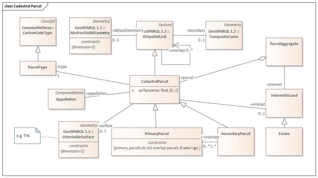
10.4.5. Class: Cadastral Parcel
A single or multi area, or solid, above, or below the surface of the earth as specified through legislated process. The extent of a cadastral parcel can be described by a surface or solid and topological relationships with other parcels.
Subclass of
-
3D Spatial Unit (From 3D Geometry and Topology Basic Profile )
Properties
| Property | Description | Cardinality | Range | Use Case Requirement |
|---|---|---|---|---|
|
from 3D Spatial Unit |
overlaps |
[0..*] |
||
|
from 3D Spatial Unit, Feature |
Constrain geometry to a form that supports calculation of interior and surface domains. hasGeometry property inherited from geo:Feature |
[0..*] |
||
|
from 3D Spatial Unit |
boundedBy |
[0..*] |
||
|
from 3D Spatial Unit |
A component geometry part potentially containing references to reusable used in the main geometry representation |
[0..*] |
||
|
from Cadastral Parcel |
appellation |
[1] |
||
|
from Cadastral Parcel |
[0..*] |
|||
|
from Cadastral Parcel |
parcel quality |
[0..1] |
||
|
from Cadastral Parcel |
The surface area of the parcel (in the units defined by the given implementation profile of this standard). |
[0..1] |
||
|
parcel:terrainIntersectionCurve from Cadastral Parcel |
parcel-terrainIntersectionCurve |
[0..1] |
||
|
from Cadastral Parcel |
parcel type |
[1] |
Images
|
Format |
|
|
Format |
|
Canonical Examples
ISO-10303-21;
HEADER;
FILE_SCHEMA(('IFC4'));
ENDSEC;
DATA;
/* site / project level information - mostly boilerplate*/
#11=IFCPROJECT('1Pv7U_QXf86vJbLHc6LgdI',$,'Project',$,$,$,$,(#20,#27),#15);
#12=IFCSIUNIT(*,.LENGTHUNIT.,$,.METRE.);
#13=IFCSIUNIT(*,.AREAUNIT.,$,.SQUARE_METRE.);
#14=IFCSIUNIT(*,.VOLUMEUNIT.,$,.CUBIC_METRE.);
#15=IFCUNITASSIGNMENT((#12,#13,#14));
#16=IFCCARTESIANPOINT((0.,0.,0.));
#17=IFCDIRECTION((0.,0.,1.));
#18=IFCDIRECTION((1.,0.,0.));
#19=IFCAXIS2PLACEMENT3D(#16,#17,#18);
#20=IFCGEOMETRICREPRESENTATIONCONTEXT($,'Model',3,1.E-05,#19,$);
#21=IFCGEOMETRICREPRESENTATIONSUBCONTEXT('Body','Model',*,*,*,*,#20,$,.MODEL_VIEW.,$);
#22=IFCGEOMETRICREPRESENTATIONSUBCONTEXT('Box','Model',*,*,*,*,#20,$,.MODEL_VIEW.,$);
#23=IFCCARTESIANPOINT((0.,0.,0.));
#24=IFCDIRECTION((0.,0.,1.));
#25=IFCDIRECTION((1.,0.,0.));
#26=IFCAXIS2PLACEMENT3D(#23,#24,#25);
#27=IFCGEOMETRICREPRESENTATIONCONTEXT($,'Plan',2,1.E-05,#26,$);
#32=IFCSITE('1KBmulBMf7MgB4kkr2pyT$',$,'Site',$,$,#47,$,$,$,$,$,$,$,$);
#34=IFCRELAGGREGATES('0MyLGeOvDDiQIJV8BnTpRw',$,$,$,#11,(#32));
#36=IFCBUILDING('23JhBYRQDDjws2fDYl7eZ5',$,'Building',$,$,#52,$,$,$,$,$,$);
#38=IFCRELAGGREGATES('0MyLGeOvDDiQIJV8BnTpRw',#37,$,$,#32,(#36));
#40=IFCBUILDINGSTOREY('23JhBYRQDDjws2fDYl7eZ5',$,'Building Storey',$,$,#52,$,$,$,$,$,$);
#42=IFCRELAGGREGATES('0MyLGeOvDDiQIJV8BnTpRw',$,$,$,#36,(#40));
#43=IFCCARTESIANPOINT((0.,0.,0.));
#44=IFCDIRECTION((0.,0.,1.));
#45=IFCDIRECTION((1.,0.,0.));
#46=IFCAXIS2PLACEMENT3D(#43,#44,#45);
#47=IFCLOCALPLACEMENT($,#46);
#48=IFCCARTESIANPOINT((0.,0.,0.));
#49=IFCDIRECTION((0.,0.,1.));
#50=IFCDIRECTION((1.,0.,0.));
#51=IFCAXIS2PLACEMENT3D(#48,#49,#50);
#52=IFCLOCALPLACEMENT(#47,#51);
/* IFC object definitions */
/* Traverse Points */
/* survey marker style material definition */
#809=IFCCOLOURRGB($,0.,0.,0.);
#810=IFCCOLOURRGB($,0.,0.,0.);
#811=IFCSURFACESTYLERENDERING(#809 ,0.,#810,$,$,$,$,$,.NOTDEFINED.);
#812=IFCSURFACESTYLE('Survey Marker Black',.BOTH.,(#811));
/* survey marker style material definition */
#813=IFCCOLOURRGB($,0.,0.,1.);
#814=IFCCOLOURRGB($,0.,0.,1.);
#815=IFCSURFACESTYLERENDERING(#813 ,0.,#814,$,$,$,$,$,.NOTDEFINED.);
#816=IFCSURFACESTYLE('Survey Marker Blue',.BOTH.,(#815));
/* style material - Gloss paint blue */
#59=IFCCOLOURRGB($,0.392156863,0.584313725,0.929411765);
#60=IFCCOLOURRGB($,0.392156863,0.584313725,0.929411765);
#61=IFCSURFACESTYLERENDERING(#59,0.,#60,$,$,$,$,$,.NOTDEFINED.);
#62=IFCSURFACESTYLE('Gloss paint blue',.BOTH.,(#61));
/* survey/traverse/occupation marker object - this is a cube */
#825=IFCINDEXEDPOLYGONALFACE((2,4,1));
#826=IFCINDEXEDPOLYGONALFACE((6,8,5));
#827=IFCINDEXEDPOLYGONALFACE((2,7,3));
#828=IFCINDEXEDPOLYGONALFACE((4,5,1));
#829=IFCINDEXEDPOLYGONALFACE((3,6,4));
#830=IFCINDEXEDPOLYGONALFACE((1,8,2));
#831=IFCINDEXEDPOLYGONALFACE((2,3,4));
#832=IFCINDEXEDPOLYGONALFACE((6,7,8));
#833=IFCINDEXEDPOLYGONALFACE((2,8,7));
#834=IFCINDEXEDPOLYGONALFACE((4,6,5));
#835=IFCINDEXEDPOLYGONALFACE((3,7,6));
#836=IFCINDEXEDPOLYGONALFACE((1,5,8));
#837=IFCCARTESIANPOINTLIST3D(((-0.1,0.1,0.1),(-0.1,-0.1,0.1),(0.1,-0.1,0.1),(0.1,0.1,0.1),(-0.1,0.1,-0.1),(0.1,0.1,-0.1),(0.1,-0.1,-0.1),(-0.1,-0.1,-0.1)));
#838=IFCPOLYGONALFACESET(#837,$,(#825,#826,#827,#828,#829,#830,#831,#832,#833,#834,#835,#836),$);
#839=IFCSHAPEREPRESENTATION(#21,'Body','Tessellation',(#838));
#1104=IFCOWNERHISTORY(#9,#8,.READWRITE.,.MODIFIED.,1638903018,#9,#8,1638903018);
#1105=IFCGEOGRAPHICELEMENT('0000000000P26',#1104,'P1','Survey Point P1 ShowLabel',$,#1110,#1114,$,.USERDEFINED.);
#1106=IFCCARTESIANPOINT((38.089, -31.596, 5.));
#1107=IFCDIRECTION((0.,0.,1.));
#1108=IFCDIRECTION((1.,0.,0.));
#1109=IFCAXIS2PLACEMENT3D(#1106,#1107,#1108);
#1110=IFCLOCALPLACEMENT($,#1109);
#1111=IFCCARTESIANPOINT((38.889, -31.396, 5.));
#1112=IFCBOUNDINGBOX(#1111 ,0.2,0.2,0.2);
#1113=IFCSHAPEREPRESENTATION(#22,'Box','BoundingBox',(#1112));
#1114=IFCPRODUCTDEFINITIONSHAPE($,$,(#1113,#839));
#6003=IFCSTYLEDITEM(#1105,(#812),'Survey Marker Black');
#840=IFCOWNERHISTORY(#9,#8,.READWRITE.,.MODIFIED.,1638903018,#9,#8,1638903018);
#841=IFCGEOGRAPHICELEMENT('0000000000P2',#840,'P2','Survey Point P2 ',$,#846,#850,$,.USERDEFINED.);
#842=IFCCARTESIANPOINT((43.089, -31.596, 5.000));
#843=IFCDIRECTION((0.,0.,1.));
#844=IFCDIRECTION((1.,0.,0.));
#845=IFCAXIS2PLACEMENT3D(#842,#843,#844);
#846=IFCLOCALPLACEMENT($,#845);
#847=IFCCARTESIANPOINT((43.889, -31.396, 5.));
#848=IFCBOUNDINGBOX(#847 ,0.2,0.2,0.2);
#849=IFCSHAPEREPRESENTATION(#22,'Box','BoundingBox',(#848));
#850=IFCPRODUCTDEFINITIONSHAPE($,$,(#849,#839));
#6004=IFCSTYLEDITEM(#841,(#816),'Survey Marker Black');
#851=IFCOWNERHISTORY(#9,#8,.READWRITE.,.MODIFIED.,1638903018,#9,#8,1638903018);
#852=IFCGEOGRAPHICELEMENT('0000000000P3',#851,'P3','Survey Point P3 ',$,#857,#861,$,.USERDEFINED.);
#853=IFCCARTESIANPOINT((43.089, -36.596, 5.000));
#854=IFCDIRECTION((0.,0.,1.));
#855=IFCDIRECTION((1.,0.,0.));
#856=IFCAXIS2PLACEMENT3D(#853,#854,#855);
#857=IFCLOCALPLACEMENT($,#856);
#858=IFCCARTESIANPOINT((43.889, -36.396, 4.8));
#859=IFCBOUNDINGBOX(#858 ,0.2,0.2,0.2);
#860=IFCSHAPEREPRESENTATION(#22,'Box','BoundingBox',(#859));
#861=IFCPRODUCTDEFINITIONSHAPE($,$,(#860,#839));
#6005=IFCSTYLEDITEM(#852,(#816),'Survey Marker Black');
#862=IFCOWNERHISTORY(#9,#8,.READWRITE.,.MODIFIED.,1638903018,#9,#8,1638903018);
#863=IFCGEOGRAPHICELEMENT('0000000000P4',#862,'P4','Survey Point P4 ',$,#868,#872,$,.USERDEFINED.);
#864=IFCCARTESIANPOINT((38.089, -36.596, 5.000));
#865=IFCDIRECTION((0.,0.,1.));
#866=IFCDIRECTION((1.,0.,0.));
#867=IFCAXIS2PLACEMENT3D(#864,#865,#866);
#868=IFCLOCALPLACEMENT($,#867);
#869=IFCCARTESIANPOINT((38.889, -36.396, 4.8));
#870=IFCBOUNDINGBOX(#869 ,0.2,0.2,0.2);
#871=IFCSHAPEREPRESENTATION(#22,'Box','BoundingBox',(#870));
#872=IFCPRODUCTDEFINITIONSHAPE($,$,(#871,#839));
#6006=IFCSTYLEDITEM(#863,(#816),'Survey Marker Black');
#961=IFCOWNERHISTORY(#9,#8,.READWRITE.,.MODIFIED.,1638903018,#9,#8,1638903018);
#962=IFCGEOGRAPHICELEMENT('0000000000P13',#961,'P13','Survey Point P13',$,#967,#971,$,.USERDEFINED.);
#963=IFCCARTESIANPOINT((43.089, -36.596, 0.000));
#964=IFCDIRECTION((0.,0.,1.));
#965=IFCDIRECTION((1.,0.,0.));
#966=IFCAXIS2PLACEMENT3D(#963,#964,#965);
#967=IFCLOCALPLACEMENT($,#966);
#968=IFCCARTESIANPOINT((43.889, -36.396, -0.200));
#969=IFCBOUNDINGBOX(#968 ,0.2,0.2,0.2);
#970=IFCSHAPEREPRESENTATION(#22,'Box','BoundingBox',(#969));
#971=IFCPRODUCTDEFINITIONSHAPE($,$,(#970,#839));
#6007=IFCSTYLEDITEM(#962,(#816),'Survey Marker Black');
#972=IFCOWNERHISTORY(#9,#8,.READWRITE.,.MODIFIED.,1638903018,#9,#8,1638903018);
#973=IFCGEOGRAPHICELEMENT('0000000000P14',#972,'P14','Survey Point P14',$,#978,#982,$,.USERDEFINED.);
#974=IFCCARTESIANPOINT((38.089, -36.596, 0.000));
#975=IFCDIRECTION((0.,0.,1.));
#976=IFCDIRECTION((1.,0.,0.));
#977=IFCAXIS2PLACEMENT3D(#974,#975,#976);
#978=IFCLOCALPLACEMENT($,#977);
#979=IFCCARTESIANPOINT((38.889, -36.396, -0.200));
#980=IFCBOUNDINGBOX(#979 ,0.2,0.2,0.2);
#981=IFCSHAPEREPRESENTATION(#22,'Box','BoundingBox',(#980));
#982=IFCPRODUCTDEFINITIONSHAPE($,$,(#981,#839));
#6008=IFCSTYLEDITEM(#973,(#816),'Survey Marker Black');
#983=IFCOWNERHISTORY(#9,#8,.READWRITE.,.MODIFIED.,1638903018,#9,#8,1638903018);
#984=IFCGEOGRAPHICELEMENT('0000000000P15',#983,'P15','Survey Point P15',$,#989,#993,$,.USERDEFINED.);
#985=IFCCARTESIANPOINT((38.089, -31.596, 0.000));
#986=IFCDIRECTION((0.,0.,1.));
#987=IFCDIRECTION((1.,0.,0.));
#988=IFCAXIS2PLACEMENT3D(#985,#986,#987);
#989=IFCLOCALPLACEMENT($,#988);
#990=IFCCARTESIANPOINT((38.889, -31.396, -0.200));
#991=IFCBOUNDINGBOX(#990 ,0.2,0.2,0.2);
#992=IFCSHAPEREPRESENTATION(#22,'Box','BoundingBox',(#991));
#993=IFCPRODUCTDEFINITIONSHAPE($,$,(#992,#839));
#6009=IFCSTYLEDITEM(#984,(#816),'Survey Marker Black');
#994=IFCOWNERHISTORY(#9,#8,.READWRITE.,.MODIFIED.,1638903018,#9,#8,1638903018);
#995=IFCGEOGRAPHICELEMENT('0000000000P16',#994,'P16','Survey Point P16',$,#1000,#1004,$,.USERDEFINED.);
#996=IFCCARTESIANPOINT((43.089, -31.596, 0.000));
#997=IFCDIRECTION((0.,0.,1.));
#998=IFCDIRECTION((1.,0.,0.));
#999=IFCAXIS2PLACEMENT3D(#996,#997,#998);
#1000=IFCLOCALPLACEMENT($,#999);
#1001=IFCCARTESIANPOINT((43.889, -31.396, -0.200));
#1002=IFCBOUNDINGBOX(#1001 ,0.2,0.2,0.2);
#1003=IFCSHAPEREPRESENTATION(#22,'Box','BoundingBox',(#1002));
#1004=IFCPRODUCTDEFINITIONSHAPE($,$,(#1003,#839));
#6010=IFCSTYLEDITEM(#995,(#816),'Survey Marker Black');
#1005=IFCOWNERHISTORY(#9,#8,.READWRITE.,.MODIFIED.,1638903018,#9,#8,1638903018);
#1006=IFCGEOGRAPHICELEMENT('0000000000P17',#1005,'P17','Survey Point P17',$,#1011,#1015,$,.USERDEFINED.);
#1007=IFCCARTESIANPOINT((42.252, -35.717, 2.530));
#1008=IFCDIRECTION((0.,0.,1.));
#1009=IFCDIRECTION((1.,0.,0.));
#1010=IFCAXIS2PLACEMENT3D(#1007,#1008,#1009);
#1011=IFCLOCALPLACEMENT($,#1010);
#1012=IFCCARTESIANPOINT((42.052, -35.517, 2.330));
#1013=IFCBOUNDINGBOX(#1012 ,0.2,0.2,0.2);
#1014=IFCSHAPEREPRESENTATION(#22,'Box','BoundingBox',(#1013));
#1015=IFCPRODUCTDEFINITIONSHAPE($,$,(#1014,#839));
#6011=IFCSTYLEDITEM(#1006,(#816),'Survey Marker Black');
#1016=IFCOWNERHISTORY(#9,#8,.READWRITE.,.MODIFIED.,1638903018,#9,#8,1638903018);
#1017=IFCGEOGRAPHICELEMENT('0000000000P18',#1016,'P18','Survey Point P18',$,#1022,#1026,$,.USERDEFINED.);
#1018=IFCCARTESIANPOINT((42.252, -35.717, 4.550));
#1019=IFCDIRECTION((0.,0.,1.));
#1020=IFCDIRECTION((1.,0.,0.));
#1021=IFCAXIS2PLACEMENT3D(#1018,#1019,#1020);
#1022=IFCLOCALPLACEMENT($,#1021);
#1023=IFCCARTESIANPOINT((42.052, -35.517, 4.350));
#1024=IFCBOUNDINGBOX(#1023 ,0.2,0.2,0.2);
#1025=IFCSHAPEREPRESENTATION(#22,'Box','BoundingBox',(#1024));
#1026=IFCPRODUCTDEFINITIONSHAPE($,$,(#1025,#839));
#6012=IFCSTYLEDITEM(#1017,(#816),'Survey Marker Black');
#1027=IFCOWNERHISTORY(#9,#8,.READWRITE.,.MODIFIED.,1638903018,#9,#8,1638903018);
#1028=IFCGEOGRAPHICELEMENT('0000000000P19',#1027,'P19','Survey Point P19',$,#1033,#1037,$,.USERDEFINED.);
#1029=IFCCARTESIANPOINT((42.252, -33.717, 4.550));
#1030=IFCDIRECTION((0.,0.,1.));
#1031=IFCDIRECTION((1.,0.,0.));
#1032=IFCAXIS2PLACEMENT3D(#1029,#1030,#1031);
#1033=IFCLOCALPLACEMENT($,#1032);
#1034=IFCCARTESIANPOINT((42.152, -33.517, 4.350));
#1035=IFCBOUNDINGBOX(#1034 ,0.2,0.2,0.2);
#1036=IFCSHAPEREPRESENTATION(#22,'Box','BoundingBox',(#1035));
#1037=IFCPRODUCTDEFINITIONSHAPE($,$,(#1036,#839));
#6013=IFCSTYLEDITEM(#1028,(#816),'Survey Marker Black');
#1038=IFCOWNERHISTORY(#9,#8,.READWRITE.,.MODIFIED.,1638903018,#9,#8,1638903018);
#1039=IFCGEOGRAPHICELEMENT('0000000000P20',#1038,'P20','Survey Point P20',$,#1044,#1048,$,.USERDEFINED.);
#1040=IFCCARTESIANPOINT((42.252, -33.717, 2.530));
#1041=IFCDIRECTION((0.,0.,1.));
#1042=IFCDIRECTION((1.,0.,0.));
#1043=IFCAXIS2PLACEMENT3D(#1040,#1041,#1042);
#1044=IFCLOCALPLACEMENT($,#1043);
#1045=IFCCARTESIANPOINT((42.052, -33.517, 2.330));
#1046=IFCBOUNDINGBOX(#1045 ,0.2,0.2,0.2);
#1047=IFCSHAPEREPRESENTATION(#22,'Box','BoundingBox',(#1046));
#1048=IFCPRODUCTDEFINITIONSHAPE($,$,(#1047,#839));
#6014=IFCSTYLEDITEM(#1039,(#816),'Survey Marker Black');
#917=IFCOWNERHISTORY(#9,#8,.READWRITE.,.MODIFIED.,1638903018,#9,#8,1638903018);
#918=IFCGEOGRAPHICELEMENT('0000000000P9',#917,'P9','Survey Point P9',$,#923,#927,$,.USERDEFINED.);
#919=IFCCARTESIANPOINT((43.089, -35.717, 4.550));
#920=IFCDIRECTION((0.,0.,1.));
#921=IFCDIRECTION((1.,0.,0.));
#922=IFCAXIS2PLACEMENT3D(#919,#920,#921);
#923=IFCLOCALPLACEMENT($,#922);
#924=IFCCARTESIANPOINT((43.889, -35.517, 4.350));
#925=IFCBOUNDINGBOX(#924 ,0.2,0.2,0.2);
#926=IFCSHAPEREPRESENTATION(#22,'Box','BoundingBox',(#925));
#927=IFCPRODUCTDEFINITIONSHAPE($,$,(#926,#839));
#6015=IFCSTYLEDITEM(#918,(#816),'Survey Marker Black');
#928=IFCOWNERHISTORY(#9,#8,.READWRITE.,.MODIFIED.,1638903018,#9,#8,1638903018);
#929=IFCGEOGRAPHICELEMENT('0000000000P10',#928,'P10','Survey Point P10 ShowLabel',$,#934,#938,$,.USERDEFINED.);
#930=IFCCARTESIANPOINT((43.089, -33.717, 4.550));
#931=IFCDIRECTION((0.,0.,1.));
#932=IFCDIRECTION((1.,0.,0.));
#933=IFCAXIS2PLACEMENT3D(#930,#931,#932);
#934=IFCLOCALPLACEMENT($,#933);
#935=IFCCARTESIANPOINT((43.889, -33.517, 4.350));
#936=IFCBOUNDINGBOX(#935 ,0.2,0.2,0.2);
#937=IFCSHAPEREPRESENTATION(#22,'Box','BoundingBox',(#936));
#938=IFCPRODUCTDEFINITIONSHAPE($,$,(#937,#839));
#6016=IFCSTYLEDITEM(#929,(#812),'Survey Marker Black');
#939=IFCOWNERHISTORY(#9,#8,.READWRITE.,.MODIFIED.,1638903018,#9,#8,1638903018);
#940=IFCGEOGRAPHICELEMENT('0000000000P11',#939,'P11','Survey Point P11',$,#945,#949,$,.USERDEFINED.);
#941=IFCCARTESIANPOINT((43.089, -33.717, 2.530));
#942=IFCDIRECTION((0.,0.,1.));
#943=IFCDIRECTION((1.,0.,0.));
#944=IFCAXIS2PLACEMENT3D(#941,#942,#943);
#945=IFCLOCALPLACEMENT($,#944);
#946=IFCCARTESIANPOINT((43.889, -33.517, 2.330));
#947=IFCBOUNDINGBOX(#946 ,0.2,0.2,0.2);
#948=IFCSHAPEREPRESENTATION(#22,'Box','BoundingBox',(#947));
#949=IFCPRODUCTDEFINITIONSHAPE($,$,(#948,#839));
#6017=IFCSTYLEDITEM(#940,(#816),'Survey Marker Black');
#950=IFCOWNERHISTORY(#9,#8,.READWRITE.,.MODIFIED.,1638903018,#9,#8,1638903018);
#951=IFCGEOGRAPHICELEMENT('0000000000P12',#950,'P12','Survey Point P12',$,#956,#960,$,.USERDEFINED.);
#952=IFCCARTESIANPOINT((43.089, -35.717, 2.530));
#953=IFCDIRECTION((0.,0.,1.));
#954=IFCDIRECTION((1.,0.,0.));
#955=IFCAXIS2PLACEMENT3D(#952,#953,#954);
#956=IFCLOCALPLACEMENT($,#955);
#957=IFCCARTESIANPOINT((43.889, -35.517, 2.330));
#958=IFCBOUNDINGBOX(#957 ,0.2,0.2,0.2);
#959=IFCSHAPEREPRESENTATION(#22,'Box','BoundingBox',(#958));
#960=IFCPRODUCTDEFINITIONSHAPE($,$,(#959,#839));
#6018=IFCSTYLEDITEM(#951,(#816),'Survey Marker Black');
#71=IFCOWNERHISTORY(#9,#8,.READWRITE.,.MODIFIED.,1638903015,#9,#8,1638903015);
#72=IFCWALL('0ZDZ3jCJ57Hw5fLEKxhgem',#71,'blue_bottom',$,$,#77,#90,$,.SOLIDWALL.);
#73=IFCCARTESIANPOINT((38.0890007019043,-36.5960006713867,0.100000001490116));
#74=IFCDIRECTION((0.,1.,1.19248806385031E-08));
#75=IFCDIRECTION((1.,0.,0.));
#76=IFCAXIS2PLACEMENT3D(#73,#74,#75);
#77=IFCLOCALPLACEMENT($,#76);
#78=IFCINDEXEDPOLYGONALFACE((1,5,6,2));
#79=IFCINDEXEDPOLYGONALFACE((2,6,7,3));
#80=IFCINDEXEDPOLYGONALFACE((3,7,8,4));
#81=IFCINDEXEDPOLYGONALFACE((4,8,5,1));
#82=IFCINDEXEDPOLYGONALFACE((2,3,4,1));
#83=IFCINDEXEDPOLYGONALFACE((5,8,7,6));
#84=IFCCARTESIANPOINTLIST3D(((0.115122802555561,0.000348226400092244,-0.),(0.115122802555561,0.000348226400092244,5.),(0.114820323884487,0.100347764790058,5.),(0.114820323884487,0.100347764790058,-0.),(4.8999547958374,0.0148215098306537,-0.),(4.8999547958374,0.0148215098306537,5.),(4.89965200424194,0.114821046590805,5.),(4.89965200424194,0.114821046590805,-0.)));
#85=IFCPOLYGONALFACESET(#84,$,(#78,#79,#80,#81,#82,#83),$);
#86=IFCSHAPEREPRESENTATION(#21,'Body','Tessellation',(#85));
#87=IFCCARTESIANPOINT((0.114820323884487,0.000348226400092244,-0.));
#88=IFCBOUNDINGBOX(#87,5.,5.,5.);
#89=IFCSHAPEREPRESENTATION(#22,'Box','BoundingBox',(#88));
#90=IFCPRODUCTDEFINITIONSHAPE($,$,(#89,#86));
#91=IFCOWNERHISTORY(#9,#8,.READWRITE.,.ADDED.,1638903015,#9,#8,1638903015);
#92=IFCELEMENTQUANTITY('00OYWqfTf4LOsVA4fhxz9U',#91,'Qto_WallBaseQuantities',$,$,(#95,#96,#97,#98,#99));
#93=IFCOWNERHISTORY(#9,#8,.READWRITE.,.ADDED.,1638903015,#9,#8,1638903015);
#94=IFCRELDEFINESBYPROPERTIES('0yhGp9U619jQNJ3jCNGeGY',#93,$,$,(#72),#92);
#95=IFCQUANTITYLENGTH('Length',$,$,9.57,$);
#96=IFCQUANTITYLENGTH('Width',$,$,0.1,$);
#97=IFCQUANTITYLENGTH('Height',$,$,5.,$);
#98=IFCQUANTITYVOLUME('GrossVolume',$,$,2.39,$);
#99=IFCQUANTITYVOLUME('NetVolume',$,$,2.39,$);
#100=IFCOWNERHISTORY(#9,#8,.READWRITE.,.MODIFIED.,1638903015,#9,#8,1638903015);
#101=IFCWALL('2V4MkMOGj4E8ApC9tnAKLP',#100,'blue_front_above_ground',$,$,#106,#119,$,.SOLIDWALL.);
#102=IFCCARTESIANPOINT((38.0890007019043,-36.5960006713867,0.300000011920929));
#103=IFCDIRECTION((0.,0.,1.));
#104=IFCDIRECTION((1.,0.,0.));
#105=IFCAXIS2PLACEMENT3D(#102,#103,#104);
#106=IFCLOCALPLACEMENT($,#105);
#107=IFCINDEXEDPOLYGONALFACE((1,5,6,2));
#108=IFCINDEXEDPOLYGONALFACE((2,6,7,3));
#109=IFCINDEXEDPOLYGONALFACE((3,7,8,4));
#110=IFCINDEXEDPOLYGONALFACE((4,8,5,1));
#111=IFCINDEXEDPOLYGONALFACE((2,3,4,1));
#112=IFCINDEXEDPOLYGONALFACE((5,8,7,6));
#113=IFCCARTESIANPOINTLIST3D(((0.115122802555561,0.000348226400092244,-0.),(0.115122802555561,0.000348226400092244,4.69999980926514),(0.114820323884487,0.100347764790058,4.69999980926514),(0.114820323884487,0.100347764790058,-0.),(4.8999547958374,0.0148215098306537,-0.),(4.8999547958374,0.0148215098306537,4.69999980926514),(4.89965200424194,0.114821046590805,4.69999980926514),(4.89965200424194,0.114821046590805,-0.)));
#114=IFCPOLYGONALFACESET(#113,$,(#107,#108,#109,#110,#111,#112),$);
#115=IFCSHAPEREPRESENTATION(#21,'Body','Tessellation',(#114));
#116=IFCCARTESIANPOINT((0.114820323884487,0.000348226400092244,-0.));
#117=IFCBOUNDINGBOX(#116,5.,5.,5.);
#118=IFCSHAPEREPRESENTATION(#22,'Box','BoundingBox',(#117));
#119=IFCPRODUCTDEFINITIONSHAPE($,$,(#118,#115));
#120=IFCOWNERHISTORY(#9,#8,.READWRITE.,.ADDED.,1638903015,#9,#8,1638903015);
#121=IFCELEMENTQUANTITY('287UxcYyP2Q9J3SjYrBsJy',#120,'Qto_WallBaseQuantities',$,$,(#124,#125,#126,#127,#128));
#122=IFCOWNERHISTORY(#9,#8,.READWRITE.,.ADDED.,1638903015,#9,#8,1638903015);
#123=IFCRELDEFINESBYPROPERTIES('1$8j1HnBz6J88Wb3x3CAj_',#122,$,$,(#101),#121);
#124=IFCQUANTITYLENGTH('Length',$,$,9.57,$);
#125=IFCQUANTITYLENGTH('Width',$,$,0.1,$);
#126=IFCQUANTITYLENGTH('Height',$,$,4.7,$);
#127=IFCQUANTITYVOLUME('GrossVolume',$,$,2.25,$);
#128=IFCQUANTITYVOLUME('NetVolume',$,$,2.25,$);
#129=IFCOWNERHISTORY(#9,#8,.READWRITE.,.MODIFIED.,1638903015,#9,#8,1638903015);
#130=IFCWALL('0Pj$j_uQ1AC8UbxYN6nDdg',#129,'blue_front_below_ground',$,$,#135,#148,$,.SOLIDWALL.);
#131=IFCCARTESIANPOINT((38.0890007019043,-36.5960006713867,0.));
#132=IFCDIRECTION((0.,0.,1.));
#133=IFCDIRECTION((1.,0.,0.));
#134=IFCAXIS2PLACEMENT3D(#131,#132,#133);
#135=IFCLOCALPLACEMENT($,#134);
#136=IFCINDEXEDPOLYGONALFACE((1,5,6,2));
#137=IFCINDEXEDPOLYGONALFACE((2,6,7,3));
#138=IFCINDEXEDPOLYGONALFACE((3,7,8,4));
#139=IFCINDEXEDPOLYGONALFACE((4,8,5,1));
#140=IFCINDEXEDPOLYGONALFACE((2,3,4,1));
#141=IFCINDEXEDPOLYGONALFACE((5,8,7,6));
#142=IFCCARTESIANPOINTLIST3D(((0.115122802555561,0.000348226400092244,-0.),(0.115122802555561,0.000348226400092244,0.300000011920929),(0.114820323884487,0.100347764790058,0.300000011920929),(0.114820323884487,0.100347764790058,-0.),(4.8999547958374,0.0148215098306537,-0.),(4.8999547958374,0.0148215098306537,0.300000011920929),(4.89965200424194,0.114821046590805,0.300000011920929),(4.89965200424194,0.114821046590805,-0.)));
#143=IFCPOLYGONALFACESET(#142,$,(#136,#137,#138,#139,#140,#141),$);
#144=IFCSHAPEREPRESENTATION(#21,'Body','Tessellation',(#143));
#145=IFCCARTESIANPOINT((0.114820323884487,0.000348226400092244,-0.));
#146=IFCBOUNDINGBOX(#145,5.,5.,5.);
#147=IFCSHAPEREPRESENTATION(#22,'Box','BoundingBox',(#146));
#148=IFCPRODUCTDEFINITIONSHAPE($,$,(#147,#144));
#149=IFCOWNERHISTORY(#9,#8,.READWRITE.,.ADDED.,1638903015,#9,#8,1638903015);
#150=IFCELEMENTQUANTITY('1iabEfUUT9ZBZbbKYHHNNq',#149,'Qto_WallBaseQuantities',$,$,(#153,#154,#155,#156,#157));
#151=IFCOWNERHISTORY(#9,#8,.READWRITE.,.ADDED.,1638903015,#9,#8,1638903015);
#152=IFCRELDEFINESBYPROPERTIES('0lwAAcoFP0thWTNM4DSKWX',#151,$,$,(#130),#150);
#153=IFCQUANTITYLENGTH('Length',$,$,9.57,$);
#154=IFCQUANTITYLENGTH('Width',$,$,0.1,$);
#155=IFCQUANTITYLENGTH('Height',$,$,0.3,$);
#156=IFCQUANTITYVOLUME('GrossVolume',$,$,0.14,$);
#157=IFCQUANTITYVOLUME('NetVolume',$,$,0.14,$);
#158=IFCOWNERHISTORY(#9,#8,.READWRITE.,.MODIFIED.,1638903015,#9,#8,1638903015);
#159=IFCWALL('3zDy7ve$93B9oYmgkgIjTt',#158,'blue_left_above_ground',$,$,#164,#177,$,.SOLIDWALL.);
#160=IFCCARTESIANPOINT((38.0890007019043,-31.5960006713867,0.300000011920929));
#161=IFCDIRECTION((0.,0.,1.));
#162=IFCDIRECTION((1.19248806385031E-08,-1.,0.));
#163=IFCAXIS2PLACEMENT3D(#160,#161,#162);
#164=IFCLOCALPLACEMENT($,#163);
#165=IFCINDEXEDPOLYGONALFACE((1,5,6,2));
#166=IFCINDEXEDPOLYGONALFACE((2,6,7,3));
#167=IFCINDEXEDPOLYGONALFACE((3,7,8,4));
#168=IFCINDEXEDPOLYGONALFACE((4,8,5,1));
#169=IFCINDEXEDPOLYGONALFACE((2,3,4,1));
#170=IFCINDEXEDPOLYGONALFACE((5,8,7,6));
#171=IFCCARTESIANPOINTLIST3D(((0.,0.,-0.),(0.,0.,4.69999980926514),(-0.000302481203107163,0.0999995395541191,4.69999980926514),(-0.000302481203107163,0.0999995395541191,-0.),(4.99997711181641,0.0151240592822433,-0.),(4.99997711181641,0.0151240592822433,4.69999980926514),(4.99967479705811,0.115123599767685,4.69999980926514),(4.99967479705811,0.115123599767685,-0.)));
#172=IFCPOLYGONALFACESET(#171,$,(#165,#166,#167,#168,#169,#170),$);
#173=IFCSHAPEREPRESENTATION(#21,'Body','Tessellation',(#172));
#174=IFCCARTESIANPOINT((-0.000302481203107163,0.,-0.));
#175=IFCBOUNDINGBOX(#174,5.,5.,5.);
#176=IFCSHAPEREPRESENTATION(#22,'Box','BoundingBox',(#175));
#177=IFCPRODUCTDEFINITIONSHAPE($,$,(#176,#173));
#178=IFCOWNERHISTORY(#9,#8,.READWRITE.,.ADDED.,1638903015,#9,#8,1638903015);
#179=IFCELEMENTQUANTITY('3iiDuUrQb3JvzQkbH3yjpY',#178,'Qto_WallBaseQuantities',$,$,(#182,#183,#184,#185,#186));
#180=IFCOWNERHISTORY(#9,#8,.READWRITE.,.ADDED.,1638903015,#9,#8,1638903015);
#181=IFCRELDEFINESBYPROPERTIES('3AB7qQcqH8XQ4avUWOQYmq',#180,$,$,(#159),#179);
#182=IFCQUANTITYLENGTH('Length',$,$,10.,$);
#183=IFCQUANTITYLENGTH('Width',$,$,0.1,$);
#184=IFCQUANTITYLENGTH('Height',$,$,4.7,$);
#185=IFCQUANTITYVOLUME('GrossVolume',$,$,2.35,$);
#186=IFCQUANTITYVOLUME('NetVolume',$,$,2.35,$);
#187=IFCOWNERHISTORY(#9,#8,.READWRITE.,.MODIFIED.,1638903015,#9,#8,1638903015);
#188=IFCWALL('0_Nvu$MCr5xPQL_UDcevAD',#187,'blue_left_below_ground',$,$,#193,#206,$,.SOLIDWALL.);
#189=IFCCARTESIANPOINT((38.0890007019043,-31.5960006713867,0.));
#190=IFCDIRECTION((0.,0.,1.));
#191=IFCDIRECTION((1.19248806385031E-08,-1.,0.));
#192=IFCAXIS2PLACEMENT3D(#189,#190,#191);
#193=IFCLOCALPLACEMENT($,#192);
#194=IFCINDEXEDPOLYGONALFACE((1,5,6,2));
#195=IFCINDEXEDPOLYGONALFACE((2,6,7,3));
#196=IFCINDEXEDPOLYGONALFACE((3,7,8,4));
#197=IFCINDEXEDPOLYGONALFACE((4,8,5,1));
#198=IFCINDEXEDPOLYGONALFACE((2,3,4,1));
#199=IFCINDEXEDPOLYGONALFACE((5,8,7,6));
#200=IFCCARTESIANPOINTLIST3D(((0.,0.,-0.),(0.,0.,0.300000011920929),(-0.000302481203107163,0.0999995395541191,0.300000011920929),(-0.000302481203107163,0.0999995395541191,-0.),(4.99997711181641,0.0151240592822433,-0.),(4.99997711181641,0.0151240592822433,0.300000011920929),(4.99967479705811,0.115123599767685,0.300000011920929),(4.99967479705811,0.115123599767685,-0.)));
#201=IFCPOLYGONALFACESET(#200,$,(#194,#195,#196,#197,#198,#199),$);
#202=IFCSHAPEREPRESENTATION(#21,'Body','Tessellation',(#201));
#203=IFCCARTESIANPOINT((-0.000302481203107163,0.,-0.));
#204=IFCBOUNDINGBOX(#203,5.,5.,5.);
#205=IFCSHAPEREPRESENTATION(#22,'Box','BoundingBox',(#204));
#206=IFCPRODUCTDEFINITIONSHAPE($,$,(#205,#202));
#207=IFCOWNERHISTORY(#9,#8,.READWRITE.,.ADDED.,1638903015,#9,#8,1638903015);
#208=IFCELEMENTQUANTITY('07czp0AcrBe9IMMUoawVu_',#207,'Qto_WallBaseQuantities',$,$,(#211,#212,#213,#214,#215));
#209=IFCOWNERHISTORY(#9,#8,.READWRITE.,.ADDED.,1638903015,#9,#8,1638903015);
#210=IFCRELDEFINESBYPROPERTIES('0dc6e5x2D3MB15C0VLFU9L',#209,$,$,(#188),#208);
#211=IFCQUANTITYLENGTH('Length',$,$,10.,$);
#212=IFCQUANTITYLENGTH('Width',$,$,0.1,$);
#213=IFCQUANTITYLENGTH('Height',$,$,0.3,$);
#214=IFCQUANTITYVOLUME('GrossVolume',$,$,0.15,$);
#215=IFCQUANTITYVOLUME('NetVolume',$,$,0.15,$);
#216=IFCOWNERHISTORY(#9,#8,.READWRITE.,.MODIFIED.,1638903015,#9,#8,1638903015);
#217=IFCWALL('1CscwCyIL6s8mT9FmGysNV',#216,'blue_rear_above_ground',$,$,#222,#235,$,.SOLIDWALL.);
#218=IFCCARTESIANPOINT((43.0890007019043,-31.5960006713867,0.300000011920929));
#219=IFCDIRECTION((0.,0.,1.));
#220=IFCDIRECTION((-1.,-3.25841369885893E-07,0.));
#221=IFCAXIS2PLACEMENT3D(#218,#219,#220);
#222=IFCLOCALPLACEMENT($,#221);
#223=IFCINDEXEDPOLYGONALFACE((1,5,6,2));
#224=IFCINDEXEDPOLYGONALFACE((2,6,7,3));
#225=IFCINDEXEDPOLYGONALFACE((3,7,8,4));
#226=IFCINDEXEDPOLYGONALFACE((4,8,5,1));
#227=IFCINDEXEDPOLYGONALFACE((2,3,4,1));
#228=IFCINDEXEDPOLYGONALFACE((5,8,7,6));
#229=IFCCARTESIANPOINTLIST3D(((0.115124225616455,0.000348230707459152,-0.),(0.115124225616455,0.000348230707459152,4.69999980926514),(0.114821746945381,0.100347772240639,4.69999980926514),(0.114821746945381,0.100347772240639,-0.),(4.8999547958374,0.0148215098306537,-0.),(4.8999547958374,0.0148215098306537,4.69999980926514),(4.89965200424194,0.114821046590805,4.69999980926514),(4.89965200424194,0.114821046590805,-0.)));
#230=IFCPOLYGONALFACESET(#229,$,(#223,#224,#225,#226,#227,#228),$);
#231=IFCSHAPEREPRESENTATION(#21,'Body','Tessellation',(#230));
#232=IFCCARTESIANPOINT((0.114821746945381,0.000348230707459152,-0.));
#233=IFCBOUNDINGBOX(#232,5.,5.,5.);
#234=IFCSHAPEREPRESENTATION(#22,'Box','BoundingBox',(#233));
#235=IFCPRODUCTDEFINITIONSHAPE($,$,(#234,#231));
#236=IFCOWNERHISTORY(#9,#8,.READWRITE.,.ADDED.,1638903015,#9,#8,1638903015);
#237=IFCELEMENTQUANTITY('0kjU8tcW9BZ8iYoK4d7J74',#236,'Qto_WallBaseQuantities',$,$,(#240,#241,#242,#243,#244));
#238=IFCOWNERHISTORY(#9,#8,.READWRITE.,.ADDED.,1638903015,#9,#8,1638903015);
#239=IFCRELDEFINESBYPROPERTIES('3s3Ubvwu1AyAVvOn0p4C5u',#238,$,$,(#217),#237);
#240=IFCQUANTITYLENGTH('Length',$,$,9.57,$);
#241=IFCQUANTITYLENGTH('Width',$,$,0.1,$);
#242=IFCQUANTITYLENGTH('Height',$,$,4.7,$);
#243=IFCQUANTITYVOLUME('GrossVolume',$,$,2.25,$);
#244=IFCQUANTITYVOLUME('NetVolume',$,$,2.25,$);
#245=IFCOWNERHISTORY(#9,#8,.READWRITE.,.MODIFIED.,1638903016,#9,#8,1638903016);
#246=IFCWALL('3Qp2Tio6X6_hsGdiXTzWRu',#245,'blue_rear_below_ground',$,$,#251,#264,$,.SOLIDWALL.);
#247=IFCCARTESIANPOINT((43.0890007019043,-31.5960006713867,0.));
#248=IFCDIRECTION((0.,0.,1.));
#249=IFCDIRECTION((-1.,-3.25841369885893E-07,0.));
#250=IFCAXIS2PLACEMENT3D(#247,#248,#249);
#251=IFCLOCALPLACEMENT($,#250);
#252=IFCINDEXEDPOLYGONALFACE((1,5,6,2));
#253=IFCINDEXEDPOLYGONALFACE((2,6,7,3));
#254=IFCINDEXEDPOLYGONALFACE((3,7,8,4));
#255=IFCINDEXEDPOLYGONALFACE((4,8,5,1));
#256=IFCINDEXEDPOLYGONALFACE((2,3,4,1));
#257=IFCINDEXEDPOLYGONALFACE((5,8,7,6));
#258=IFCCARTESIANPOINTLIST3D(((0.115124225616455,0.000348230707459152,-0.),(0.115124225616455,0.000348230707459152,0.300000011920929),(0.114821746945381,0.100347772240639,0.300000011920929),(0.114821746945381,0.100347772240639,-0.),(4.8999547958374,0.0148215098306537,-0.),(4.8999547958374,0.0148215098306537,0.300000011920929),(4.89965200424194,0.114821046590805,0.300000011920929),(4.89965200424194,0.114821046590805,-0.)));
#259=IFCPOLYGONALFACESET(#258,$,(#252,#253,#254,#255,#256,#257),$);
#260=IFCSHAPEREPRESENTATION(#21,'Body','Tessellation',(#259));
#261=IFCCARTESIANPOINT((0.114821746945381,0.000348230707459152,-0.));
#262=IFCBOUNDINGBOX(#261,5.,5.,5.);
#263=IFCSHAPEREPRESENTATION(#22,'Box','BoundingBox',(#262));
#264=IFCPRODUCTDEFINITIONSHAPE($,$,(#263,#260));
#265=IFCOWNERHISTORY(#9,#8,.READWRITE.,.ADDED.,1638903016,#9,#8,1638903016);
#266=IFCELEMENTQUANTITY('2xeUzEs75749mejl$nY4NI',#265,'Qto_WallBaseQuantities',$,$,(#269,#270,#271,#272,#273));
#267=IFCOWNERHISTORY(#9,#8,.READWRITE.,.ADDED.,1638903016,#9,#8,1638903016);
#268=IFCRELDEFINESBYPROPERTIES('3k4Idi9cf9axIZXwQkQ_ID',#267,$,$,(#246),#266);
#269=IFCQUANTITYLENGTH('Length',$,$,9.57,$);
#270=IFCQUANTITYLENGTH('Width',$,$,0.1,$);
#271=IFCQUANTITYLENGTH('Height',$,$,0.3,$);
#272=IFCQUANTITYVOLUME('GrossVolume',$,$,0.14,$);
#273=IFCQUANTITYVOLUME('NetVolume',$,$,0.14,$);
#274=IFCOWNERHISTORY(#9,#8,.READWRITE.,.MODIFIED.,1638903016,#9,#8,1638903016);
#275=IFCWALL('129gVASXH6lfsqgVdtpKFf',#274,'blue_right_above_ground',$,$,#280,#303,$,.SOLIDWALL.);
#276=IFCCARTESIANPOINT((43.0890007019043,-36.5960006713867,0.300000011920929));
#277=IFCDIRECTION((0.,0.,1.));
#278=IFCDIRECTION((-4.37113882867379E-08,1.,0.));
#279=IFCAXIS2PLACEMENT3D(#276,#277,#278);
#280=IFCLOCALPLACEMENT($,#279);
#281=IFCINDEXEDPOLYGONALFACE((12,13,2,1,5,6,14,15,9,11,10));
#282=IFCINDEXEDPOLYGONALFACE((14,6,2,13,16));
#283=IFCINDEXEDPOLYGONALFACE((2,6,7,3));
#284=IFCINDEXEDPOLYGONALFACE((18,3,7,21,17));
#285=IFCINDEXEDPOLYGONALFACE((7,8,4,3,18,23,22,24,19,20,21));
#286=IFCINDEXEDPOLYGONALFACE((4,8,5,1));
#287=IFCINDEXEDPOLYGONALFACE((2,3,4,1));
#288=IFCINDEXEDPOLYGONALFACE((5,8,7,6));
#289=IFCINDEXEDPOLYGONALFACE((14,16,17,21));
#290=IFCINDEXEDPOLYGONALFACE((11,9,19,24));
#291=IFCINDEXEDPOLYGONALFACE((18,13,12,23));
#292=IFCINDEXEDPOLYGONALFACE((15,14,21,20));
#293=IFCINDEXEDPOLYGONALFACE((16,13,18,17));
#294=IFCINDEXEDPOLYGONALFACE((22,10,11,24));
#295=IFCINDEXEDPOLYGONALFACE((12,10,22,23));
#296=IFCINDEXEDPOLYGONALFACE((15,20,19,9));
#297=IFCCARTESIANPOINTLIST3D(((0.,0.,0.),(0.,0.,4.69999980926514),(-0.000302481203107163,0.0999995395541191,4.69999980926514),(-0.000302481203107163,0.0999995395541191,0.),(4.99997711181641,0.0151240592822433,0.),(4.99997711181641,0.0151240592822433,4.69999980926514),(4.99967479705811,0.115123599767685,4.69999980926514),(4.99967479705811,0.115123599767685,0.),(2.87900137901306,0.00870847795158625,2.23000001907349),(0.879001438617706,0.00265882606618106,2.23000001907349),(1.71082830429077,0.00517495768144727,2.23000001907349),(0.879001438617706,0.00265882606618106,3.40731334686279),(0.879001438617706,0.00265882606618106,4.25),(2.87900137901306,0.00870847795158625,4.25),(2.87900137901306,0.00870847795158625,3.0665762424469),(1.71082830429077,0.00517495768144727,4.25),(1.61112952232361,0.104873843491077,4.25),(0.879001438617706,0.102659277617931,4.25),(2.87900137901306,0.108708932995796,2.23000001907349),(2.87900137901306,0.108708932995796,2.96557569503784),(2.87900137901306,0.108708932995796,4.25),(0.879001438617706,0.102659277617931,2.23000001907349),(0.879001438617706,0.102659277617931,3.50831365585327),(1.61112952232361,0.104873843491077,2.23000001907349)));
#298=IFCPOLYGONALFACESET(#297,$,(#281,#282,#283,#284,#285,#286,#287,#288,#289,#290,#291,#292,#293,#294,#295,#296),$);
#299=IFCSHAPEREPRESENTATION(#21,'Body','Tessellation',(#298));
#300=IFCCARTESIANPOINT((-0.000302481203107163,0.,0.));
#301=IFCBOUNDINGBOX(#300,5.,5.,5.);
#302=IFCSHAPEREPRESENTATION(#22,'Box','BoundingBox',(#301));
#303=IFCPRODUCTDEFINITIONSHAPE($,$,(#302,#299));
#304=IFCOWNERHISTORY(#9,#8,.READWRITE.,.ADDED.,1638903016,#9,#8,1638903016);
#305=IFCELEMENTQUANTITY('0nOs4nPrf6wh4F0wmANHnO',#304,'Qto_WallBaseQuantities',$,$,(#308,#309,#310,#311,#312));
#306=IFCOWNERHISTORY(#9,#8,.READWRITE.,.ADDED.,1638903016,#9,#8,1638903016);
#307=IFCRELDEFINESBYPROPERTIES('11D65eHcbCGPqd8yDJmiQ1',#306,$,$,(#275),#305);
#308=IFCQUANTITYLENGTH('Length',$,$,10.,$);
#309=IFCQUANTITYLENGTH('Width',$,$,0.1,$);
#310=IFCQUANTITYLENGTH('Height',$,$,4.7,$);
#311=IFCQUANTITYVOLUME('GrossVolume',$,$,2.35,$);
#312=IFCQUANTITYVOLUME('NetVolume',$,$,2.35,$);
#313=IFCOWNERHISTORY(#9,#8,.READWRITE.,.MODIFIED.,1638903016,#9,#8,1638903016);
#314=IFCWALL('1POQQ24hzEQ80As95tMhP1',#313,'blue_right_below_ground',$,$,#319,#332,$,.SOLIDWALL.);
#315=IFCCARTESIANPOINT((43.0890007019043,-36.5960006713867,0.));
#316=IFCDIRECTION((0.,0.,1.));
#317=IFCDIRECTION((-4.37113882867379E-08,1.,0.));
#318=IFCAXIS2PLACEMENT3D(#315,#316,#317);
#319=IFCLOCALPLACEMENT($,#318);
#320=IFCINDEXEDPOLYGONALFACE((1,5,6,2));
#321=IFCINDEXEDPOLYGONALFACE((2,6,7,3));
#322=IFCINDEXEDPOLYGONALFACE((3,7,8,4));
#323=IFCINDEXEDPOLYGONALFACE((4,8,5,1));
#324=IFCINDEXEDPOLYGONALFACE((2,3,4,1));
#325=IFCINDEXEDPOLYGONALFACE((5,8,7,6));
#326=IFCCARTESIANPOINTLIST3D(((0.,0.,0.),(0.,0.,0.300000011920929),(-0.000302481203107163,0.0999995395541191,0.300000011920929),(-0.000302481203107163,0.0999995395541191,0.),(4.99997711181641,0.0151240592822433,0.),(4.99997711181641,0.0151240592822433,0.300000011920929),(4.99967479705811,0.115123599767685,0.300000011920929),(4.99967479705811,0.115123599767685,0.)));
#327=IFCPOLYGONALFACESET(#326,$,(#320,#321,#322,#323,#324,#325),$);
#328=IFCSHAPEREPRESENTATION(#21,'Body','Tessellation',(#327));
#329=IFCCARTESIANPOINT((-0.000302481203107163,0.,0.));
#330=IFCBOUNDINGBOX(#329,5.,5.,5.);
#331=IFCSHAPEREPRESENTATION(#22,'Box','BoundingBox',(#330));
#332=IFCPRODUCTDEFINITIONSHAPE($,$,(#331,#328));
#333=IFCOWNERHISTORY(#9,#8,.READWRITE.,.ADDED.,1638903016,#9,#8,1638903016);
#334=IFCELEMENTQUANTITY('3Z3E2eBHXAaPhfLMDmu754',#333,'Qto_WallBaseQuantities',$,$,(#337,#338,#339,#340,#341));
#335=IFCOWNERHISTORY(#9,#8,.READWRITE.,.ADDED.,1638903016,#9,#8,1638903016);
#336=IFCRELDEFINESBYPROPERTIES('00YhtGu$r2NQjr1aNTofM7',#335,$,$,(#314),#334);
#337=IFCQUANTITYLENGTH('Length',$,$,10.,$);
#338=IFCQUANTITYLENGTH('Width',$,$,0.1,$);
#339=IFCQUANTITYLENGTH('Height',$,$,0.3,$);
#340=IFCQUANTITYVOLUME('GrossVolume',$,$,0.15,$);
#341=IFCQUANTITYVOLUME('NetVolume',$,$,0.15,$);
#342=IFCOWNERHISTORY(#9,#8,.READWRITE.,.MODIFIED.,1638903016,#9,#8,1638903016);
#343=IFCWALL('0cpBg_MAT4f9kDeUP$2ZgH',#342,'blue_top',$,$,#348,#361,$,.SOLIDWALL.);
#344=IFCCARTESIANPOINT((38.0890007019043,-36.5960006713867,5.));
#345=IFCDIRECTION((0.,1.,1.19248806385031E-08));
#346=IFCDIRECTION((1.,0.,0.));
#347=IFCAXIS2PLACEMENT3D(#344,#345,#346);
#348=IFCLOCALPLACEMENT($,#347);
#349=IFCINDEXEDPOLYGONALFACE((1,5,6,2));
#350=IFCINDEXEDPOLYGONALFACE((2,6,7,3));
#351=IFCINDEXEDPOLYGONALFACE((3,7,8,4));
#352=IFCINDEXEDPOLYGONALFACE((4,8,5,1));
#353=IFCINDEXEDPOLYGONALFACE((2,3,4,1));
#354=IFCINDEXEDPOLYGONALFACE((5,8,7,6));
#355=IFCCARTESIANPOINTLIST3D(((0.115122802555561,0.000348226400092244,-0.),(0.115122802555561,0.000348226400092244,5.),(0.114820323884487,0.100347764790058,5.),(0.114820323884487,0.100347764790058,-0.),(4.8999547958374,0.0148215098306537,-0.),(4.8999547958374,0.0148215098306537,5.),(4.89965200424194,0.114821046590805,5.),(4.89965200424194,0.114821046590805,-0.)));
#356=IFCPOLYGONALFACESET(#355,$,(#349,#350,#351,#352,#353,#354),$);
#357=IFCSHAPEREPRESENTATION(#21,'Body','Tessellation',(#356));
#358=IFCCARTESIANPOINT((0.114820323884487,0.000348226400092244,-0.));
#359=IFCBOUNDINGBOX(#358,5.,5.,5.);
#360=IFCSHAPEREPRESENTATION(#22,'Box','BoundingBox',(#359));
#361=IFCPRODUCTDEFINITIONSHAPE($,$,(#360,#357));
#362=IFCOWNERHISTORY(#9,#8,.READWRITE.,.ADDED.,1638903016,#9,#8,1638903016);
#363=IFCELEMENTQUANTITY('2cnXfFVQj6_BPPvY_mrHPV',#362,'Qto_WallBaseQuantities',$,$,(#366,#367,#368,#369,#370));
#364=IFCOWNERHISTORY(#9,#8,.READWRITE.,.ADDED.,1638903016,#9,#8,1638903016);
#365=IFCRELDEFINESBYPROPERTIES('3BxSiOEkjCNfKS45P119db',#364,$,$,(#343),#363);
#366=IFCQUANTITYLENGTH('Length',$,$,9.57,$);
#367=IFCQUANTITYLENGTH('Width',$,$,0.1,$);
#368=IFCQUANTITYLENGTH('Height',$,$,5.,$);
#369=IFCQUANTITYVOLUME('GrossVolume',$,$,2.39,$);
#370=IFCQUANTITYVOLUME('NetVolume',$,$,2.39,$);
#787=IFCSTYLEDITEM(#85,(#62),'Gloss paint blue');
#788=IFCSTYLEDITEM(#101,(#62),'Gloss paint blue');
#789=IFCSTYLEDITEM(#143,(#62),'Gloss paint blue');
#790=IFCSTYLEDITEM(#172,(#62),'Gloss paint blue');
#791=IFCSTYLEDITEM(#201,(#62),'Gloss paint blue');
#792=IFCSTYLEDITEM(#230,(#62),'Gloss paint blue');
#793=IFCSTYLEDITEM(#259,(#62),'Gloss paint blue');
#794=IFCSTYLEDITEM(#298,(#62),'Gloss paint blue');
#795=IFCSTYLEDITEM(#327,(#62),'Gloss paint blue');
#796=IFCSTYLEDITEM(#356,(#62),'Gloss paint blue');
#797=IFCSTYLEDITEM(#385,(#62),'Gloss paint blue');
#798=IFCSTYLEDITEM(#414,(#62),'Gloss paint blue');
#799=IFCSTYLEDITEM(#443,(#62),'Gloss paint blue');
#800=IFCSTYLEDITEM(#472,(#62),'Gloss paint blue');
#801=IFCSTYLEDITEM(#501,(#62),'Gloss paint blue');
ENDSEC;
END-ISO-10303-21;
|
|
Description |
A Cadastral Parcel defined by a boundary line in 2D. The default geometry of this as a 3D unit is not specified, but may be derived from the boundary as an Extruded Surface using implicit or explicit limits. The boundary property is a sub-property of hasGeometry - so an application could infer the boundary as an available geometry. |
|
|
|
Informative Examples
<Parcel gml:id="parcel_1">
<gml:CompositeSolid>
<gml:name>Blue spatial unit</gml:name>
<gml:solidMember>
<gml:Solid gml:id="s1">
<gml:name>dim( I(Blue Box) ∩ E(Yellow Box) = 2), ST_Disjoint</gml:name>
<gml:exterior>
<gml:Shell>
<gml:surfaceMember>
<gml:Polygon gml:id="blue_top">
<gml:exterior>
<gml:LinearRing gml:id="lr1">
<gml:pointProperty xlink:href="#p1"/>
<gml:pointProperty xlink:href="#p4"/>
<gml:pointProperty xlink:href="#p3"/>
<gml:pointProperty xlink:href="#p2"/>
<gml:pointProperty xlink:href="#p1"/>
</gml:LinearRing>
</gml:exterior>
</gml:Polygon>
</gml:surfaceMember>
|
Title |
Survey Point - GML |
|
Conforms To |
|
Show Details |
|
<parcelSurface id="65987456">
<parcelAnnotation>Retracement of Lot 1 DP 333333</parcelAnnotation>
<parcelIntent>Fee simple parcel</parcelIntent>
<parcelAppelation>Lot 1 DP 333333 North Auckland</parcelAppelation>
<surfaceArea>6867</surfaceArea>
<parcelArea>6864</parcelArea>
<titleReference>NA 56872</titleReference>
<compositeSurface>
...
</compositeSurface>
</parcelSurface >
|
Title |
Parcel-12d |
Show Details |
|
<Parcels>
...
<Parcel
name="1" area="3225.6" parcelType="Single"
state="proposed" class="Lot"
useOfParcel="Public Reserve" parcelFormat="Standard">
<Center/>
<CoordGeom></CoordGeom>
<LocationAddress></LocationAddress>
</Parcel>
<Parcel
name="2" parcelType="Multipart">
<Parcels>
<Parcel name="A" pclRef="2A"/>
<Parcel name="B" pclRef="2B"/>
</Parcels>
</Parcel>
<Parcel name="2A" parcelType="Part"></Parcel>
<Parcel name="2B" parcelType="Part"></Parcel>
<Parcel
name="E1" class="Easement"
desc="Right of Carriageway Variable Width">
<CoordGeom></CoordGeom>
</Parcel>
<Parcel
name="R1" class="Road"
desc="NICHOLSONS LANE (20.115 WIDE)">
<Center/>
<CoordGeom></CoordGeom>
</Parcel>
</ Parcels>
|
Title |
Parcel-ePlanNSW |
Show Details |
|
10.4.6. Class: Parcel Aggregate
A parcel aggregate is a collection of parcels whose collective extent may be described as a spatial unit.
|
Note
|
This superclass supports alignement with the LandInfra concept of a LandPropertyUnit without assuming that this is the only requirement to aggregate parcels. |
Subclass of
-
3D Spatial Unit (From 3D Geometry and Topology Basic Profile )
Properties
| Property | Description | Cardinality | Range | Use Case Requirement |
|---|---|---|---|---|
|
from 3D Spatial Unit |
overlaps |
[0..*] |
||
|
from 3D Spatial Unit, Feature |
Constrain geometry to a form that supports calculation of interior and surface domains. hasGeometry property inherited from geo:Feature |
[0..*] |
||
|
from 3D Spatial Unit |
boundedBy |
[0..*] |
||
|
from 3D Spatial Unit |
A component geometry part potentially containing references to reusable used in the main geometry representation |
[0..*] |
10.4.7. Class: Primary Cadastral Parcel
A parcel that may not overlap with other parcels of the same type - they represent exclusive rights. Different types of primary parcels may be nested within a given type provided no nested parcles are of this type.
Subclass of
-
Cadastral Parcel (From Cadastral Parcel )
Properties
| Property | Description | Cardinality | Range | Use Case Requirement |
|---|---|---|---|---|
|
from 3D Spatial Unit |
overlaps |
[0..*] |
||
|
from 3D Spatial Unit, Feature |
Constrain geometry to a form that supports calculation of interior and surface domains. hasGeometry property inherited from geo:Feature |
[0..*] |
||
|
from 3D Spatial Unit |
boundedBy |
[0..*] |
||
|
from 3D Spatial Unit |
A component geometry part potentially containing references to reusable used in the main geometry representation |
[0..*] |
||
|
from Cadastral Parcel |
appellation |
[1] |
||
|
from Cadastral Parcel |
[0..*] |
|||
|
from Cadastral Parcel |
parcel quality |
[0..1] |
||
|
from Cadastral Parcel |
The surface area of the parcel (in the units defined by the given implementation profile of this standard). |
[0..1] |
||
|
parcel:terrainIntersectionCurve from Cadastral Parcel |
parcel-terrainIntersectionCurve |
[0..1] |
||
|
from Cadastral Parcel |
parcel type |
[1] |
Canonical Examples
|
ISO-10303-21;
HEADER;
FILE_SCHEMA(('IFC4'));
ENDSEC;
DATA;
/* site / project level information - mostly boilerplate*/
#11=IFCPROJECT('1Pv7U_QXf86vJbLHc6LgdI',$,'Project',$,$,$,$,(#20,#27),#15);
#12=IFCSIUNIT(*,.LENGTHUNIT.,$,.METRE.);
#13=IFCSIUNIT(*,.AREAUNIT.,$,.SQUARE_METRE.);
#14=IFCSIUNIT(*,.VOLUMEUNIT.,$,.CUBIC_METRE.);
#15=IFCUNITASSIGNMENT((#12,#13,#14));
#16=IFCCARTESIANPOINT((0.,0.,0.));
#17=IFCDIRECTION((0.,0.,1.));
#18=IFCDIRECTION((1.,0.,0.));
#19=IFCAXIS2PLACEMENT3D(#16,#17,#18);
#20=IFCGEOMETRICREPRESENTATIONCONTEXT($,'Model',3,1.E-05,#19,$);
#21=IFCGEOMETRICREPRESENTATIONSUBCONTEXT('Body','Model',*,*,*,*,#20,$,.MODEL_VIEW.,$);
#22=IFCGEOMETRICREPRESENTATIONSUBCONTEXT('Box','Model',*,*,*,*,#20,$,.MODEL_VIEW.,$);
#23=IFCCARTESIANPOINT((0.,0.,0.));
#24=IFCDIRECTION((0.,0.,1.));
#25=IFCDIRECTION((1.,0.,0.));
#26=IFCAXIS2PLACEMENT3D(#23,#24,#25);
#27=IFCGEOMETRICREPRESENTATIONCONTEXT($,'Plan',2,1.E-05,#26,$);
#32=IFCSITE('1KBmulBMf7MgB4kkr2pyT$',$,'Site',$,$,#47,$,$,$,$,$,$,$,$);
#34=IFCRELAGGREGATES('0MyLGeOvDDiQIJV8BnTpRw',$,$,$,#11,(#32));
#36=IFCBUILDING('23JhBYRQDDjws2fDYl7eZ5',$,'Building',$,$,#52,$,$,$,$,$,$);
#38=IFCRELAGGREGATES('0MyLGeOvDDiQIJV8BnTpRw',#37,$,$,#32,(#36));
#40=IFCBUILDINGSTOREY('23JhBYRQDDjws2fDYl7eZ5',$,'Building Storey',$,$,#52,$,$,$,$,$,$);
#42=IFCRELAGGREGATES('0MyLGeOvDDiQIJV8BnTpRw',$,$,$,#36,(#40));
#43=IFCCARTESIANPOINT((0.,0.,0.));
#44=IFCDIRECTION((0.,0.,1.));
#45=IFCDIRECTION((1.,0.,0.));
#46=IFCAXIS2PLACEMENT3D(#43,#44,#45);
#47=IFCLOCALPLACEMENT($,#46);
#48=IFCCARTESIANPOINT((0.,0.,0.));
#49=IFCDIRECTION((0.,0.,1.));
#50=IFCDIRECTION((1.,0.,0.));
#51=IFCAXIS2PLACEMENT3D(#48,#49,#50);
#52=IFCLOCALPLACEMENT(#47,#51);
/* IFC object definitions */
/* Traverse Points */
/* survey marker style material definition */
#809=IFCCOLOURRGB($,0.,0.,0.);
#810=IFCCOLOURRGB($,0.,0.,0.);
#811=IFCSURFACESTYLERENDERING(#809 ,0.,#810,$,$,$,$,$,.NOTDEFINED.);
#812=IFCSURFACESTYLE('Survey Marker Black',.BOTH.,(#811));
/* survey marker style material definition */
#813=IFCCOLOURRGB($,0.,0.,1.);
#814=IFCCOLOURRGB($,0.,0.,1.);
#815=IFCSURFACESTYLERENDERING(#813 ,0.,#814,$,$,$,$,$,.NOTDEFINED.);
#816=IFCSURFACESTYLE('Survey Marker Blue',.BOTH.,(#815));
/* style material - Gloss paint blue */
#59=IFCCOLOURRGB($,0.392156863,0.584313725,0.929411765);
#60=IFCCOLOURRGB($,0.392156863,0.584313725,0.929411765);
#61=IFCSURFACESTYLERENDERING(#59,0.,#60,$,$,$,$,$,.NOTDEFINED.);
#62=IFCSURFACESTYLE('Gloss paint blue',.BOTH.,(#61));
/* survey/traverse/occupation marker object - this is a cube */
#825=IFCINDEXEDPOLYGONALFACE((2,4,1));
#826=IFCINDEXEDPOLYGONALFACE((6,8,5));
#827=IFCINDEXEDPOLYGONALFACE((2,7,3));
#828=IFCINDEXEDPOLYGONALFACE((4,5,1));
#829=IFCINDEXEDPOLYGONALFACE((3,6,4));
#830=IFCINDEXEDPOLYGONALFACE((1,8,2));
#831=IFCINDEXEDPOLYGONALFACE((2,3,4));
#832=IFCINDEXEDPOLYGONALFACE((6,7,8));
#833=IFCINDEXEDPOLYGONALFACE((2,8,7));
#834=IFCINDEXEDPOLYGONALFACE((4,6,5));
#835=IFCINDEXEDPOLYGONALFACE((3,7,6));
#836=IFCINDEXEDPOLYGONALFACE((1,5,8));
#837=IFCCARTESIANPOINTLIST3D(((-0.1,0.1,0.1),(-0.1,-0.1,0.1),(0.1,-0.1,0.1),(0.1,0.1,0.1),(-0.1,0.1,-0.1),(0.1,0.1,-0.1),(0.1,-0.1,-0.1),(-0.1,-0.1,-0.1)));
#838=IFCPOLYGONALFACESET(#837,$,(#825,#826,#827,#828,#829,#830,#831,#832,#833,#834,#835,#836),$);
#839=IFCSHAPEREPRESENTATION(#21,'Body','Tessellation',(#838));
#1104=IFCOWNERHISTORY(#9,#8,.READWRITE.,.MODIFIED.,1638903018,#9,#8,1638903018);
#1105=IFCGEOGRAPHICELEMENT('0000000000P26',#1104,'P1','Survey Point P1 ShowLabel',$,#1110,#1114,$,.USERDEFINED.);
#1106=IFCCARTESIANPOINT((38.089, -31.596, 5.));
#1107=IFCDIRECTION((0.,0.,1.));
#1108=IFCDIRECTION((1.,0.,0.));
#1109=IFCAXIS2PLACEMENT3D(#1106,#1107,#1108);
#1110=IFCLOCALPLACEMENT($,#1109);
#1111=IFCCARTESIANPOINT((38.889, -31.396, 5.));
#1112=IFCBOUNDINGBOX(#1111 ,0.2,0.2,0.2);
#1113=IFCSHAPEREPRESENTATION(#22,'Box','BoundingBox',(#1112));
#1114=IFCPRODUCTDEFINITIONSHAPE($,$,(#1113,#839));
#6003=IFCSTYLEDITEM(#1105,(#812),'Survey Marker Black');
#840=IFCOWNERHISTORY(#9,#8,.READWRITE.,.MODIFIED.,1638903018,#9,#8,1638903018);
#841=IFCGEOGRAPHICELEMENT('0000000000P2',#840,'P2','Survey Point P2 ',$,#846,#850,$,.USERDEFINED.);
#842=IFCCARTESIANPOINT((43.089, -31.596, 5.000));
#843=IFCDIRECTION((0.,0.,1.));
#844=IFCDIRECTION((1.,0.,0.));
#845=IFCAXIS2PLACEMENT3D(#842,#843,#844);
#846=IFCLOCALPLACEMENT($,#845);
#847=IFCCARTESIANPOINT((43.889, -31.396, 5.));
#848=IFCBOUNDINGBOX(#847 ,0.2,0.2,0.2);
#849=IFCSHAPEREPRESENTATION(#22,'Box','BoundingBox',(#848));
#850=IFCPRODUCTDEFINITIONSHAPE($,$,(#849,#839));
#6004=IFCSTYLEDITEM(#841,(#816),'Survey Marker Black');
#851=IFCOWNERHISTORY(#9,#8,.READWRITE.,.MODIFIED.,1638903018,#9,#8,1638903018);
#852=IFCGEOGRAPHICELEMENT('0000000000P3',#851,'P3','Survey Point P3 ',$,#857,#861,$,.USERDEFINED.);
#853=IFCCARTESIANPOINT((43.089, -36.596, 5.000));
#854=IFCDIRECTION((0.,0.,1.));
#855=IFCDIRECTION((1.,0.,0.));
#856=IFCAXIS2PLACEMENT3D(#853,#854,#855);
#857=IFCLOCALPLACEMENT($,#856);
#858=IFCCARTESIANPOINT((43.889, -36.396, 4.8));
#859=IFCBOUNDINGBOX(#858 ,0.2,0.2,0.2);
#860=IFCSHAPEREPRESENTATION(#22,'Box','BoundingBox',(#859));
#861=IFCPRODUCTDEFINITIONSHAPE($,$,(#860,#839));
#6005=IFCSTYLEDITEM(#852,(#816),'Survey Marker Black');
#862=IFCOWNERHISTORY(#9,#8,.READWRITE.,.MODIFIED.,1638903018,#9,#8,1638903018);
#863=IFCGEOGRAPHICELEMENT('0000000000P4',#862,'P4','Survey Point P4 ',$,#868,#872,$,.USERDEFINED.);
#864=IFCCARTESIANPOINT((38.089, -36.596, 5.000));
#865=IFCDIRECTION((0.,0.,1.));
#866=IFCDIRECTION((1.,0.,0.));
#867=IFCAXIS2PLACEMENT3D(#864,#865,#866);
#868=IFCLOCALPLACEMENT($,#867);
#869=IFCCARTESIANPOINT((38.889, -36.396, 4.8));
#870=IFCBOUNDINGBOX(#869 ,0.2,0.2,0.2);
#871=IFCSHAPEREPRESENTATION(#22,'Box','BoundingBox',(#870));
#872=IFCPRODUCTDEFINITIONSHAPE($,$,(#871,#839));
#6006=IFCSTYLEDITEM(#863,(#816),'Survey Marker Black');
#961=IFCOWNERHISTORY(#9,#8,.READWRITE.,.MODIFIED.,1638903018,#9,#8,1638903018);
#962=IFCGEOGRAPHICELEMENT('0000000000P13',#961,'P13','Survey Point P13',$,#967,#971,$,.USERDEFINED.);
#963=IFCCARTESIANPOINT((43.089, -36.596, 0.000));
#964=IFCDIRECTION((0.,0.,1.));
#965=IFCDIRECTION((1.,0.,0.));
#966=IFCAXIS2PLACEMENT3D(#963,#964,#965);
#967=IFCLOCALPLACEMENT($,#966);
#968=IFCCARTESIANPOINT((43.889, -36.396, -0.200));
#969=IFCBOUNDINGBOX(#968 ,0.2,0.2,0.2);
#970=IFCSHAPEREPRESENTATION(#22,'Box','BoundingBox',(#969));
#971=IFCPRODUCTDEFINITIONSHAPE($,$,(#970,#839));
#6007=IFCSTYLEDITEM(#962,(#816),'Survey Marker Black');
#972=IFCOWNERHISTORY(#9,#8,.READWRITE.,.MODIFIED.,1638903018,#9,#8,1638903018);
#973=IFCGEOGRAPHICELEMENT('0000000000P14',#972,'P14','Survey Point P14',$,#978,#982,$,.USERDEFINED.);
#974=IFCCARTESIANPOINT((38.089, -36.596, 0.000));
#975=IFCDIRECTION((0.,0.,1.));
#976=IFCDIRECTION((1.,0.,0.));
#977=IFCAXIS2PLACEMENT3D(#974,#975,#976);
#978=IFCLOCALPLACEMENT($,#977);
#979=IFCCARTESIANPOINT((38.889, -36.396, -0.200));
#980=IFCBOUNDINGBOX(#979 ,0.2,0.2,0.2);
#981=IFCSHAPEREPRESENTATION(#22,'Box','BoundingBox',(#980));
#982=IFCPRODUCTDEFINITIONSHAPE($,$,(#981,#839));
#6008=IFCSTYLEDITEM(#973,(#816),'Survey Marker Black');
#983=IFCOWNERHISTORY(#9,#8,.READWRITE.,.MODIFIED.,1638903018,#9,#8,1638903018);
#984=IFCGEOGRAPHICELEMENT('0000000000P15',#983,'P15','Survey Point P15',$,#989,#993,$,.USERDEFINED.);
#985=IFCCARTESIANPOINT((38.089, -31.596, 0.000));
#986=IFCDIRECTION((0.,0.,1.));
#987=IFCDIRECTION((1.,0.,0.));
#988=IFCAXIS2PLACEMENT3D(#985,#986,#987);
#989=IFCLOCALPLACEMENT($,#988);
#990=IFCCARTESIANPOINT((38.889, -31.396, -0.200));
#991=IFCBOUNDINGBOX(#990 ,0.2,0.2,0.2);
#992=IFCSHAPEREPRESENTATION(#22,'Box','BoundingBox',(#991));
#993=IFCPRODUCTDEFINITIONSHAPE($,$,(#992,#839));
#6009=IFCSTYLEDITEM(#984,(#816),'Survey Marker Black');
#994=IFCOWNERHISTORY(#9,#8,.READWRITE.,.MODIFIED.,1638903018,#9,#8,1638903018);
#995=IFCGEOGRAPHICELEMENT('0000000000P16',#994,'P16','Survey Point P16',$,#1000,#1004,$,.USERDEFINED.);
#996=IFCCARTESIANPOINT((43.089, -31.596, 0.000));
#997=IFCDIRECTION((0.,0.,1.));
#998=IFCDIRECTION((1.,0.,0.));
#999=IFCAXIS2PLACEMENT3D(#996,#997,#998);
#1000=IFCLOCALPLACEMENT($,#999);
#1001=IFCCARTESIANPOINT((43.889, -31.396, -0.200));
#1002=IFCBOUNDINGBOX(#1001 ,0.2,0.2,0.2);
#1003=IFCSHAPEREPRESENTATION(#22,'Box','BoundingBox',(#1002));
#1004=IFCPRODUCTDEFINITIONSHAPE($,$,(#1003,#839));
#6010=IFCSTYLEDITEM(#995,(#816),'Survey Marker Black');
#1005=IFCOWNERHISTORY(#9,#8,.READWRITE.,.MODIFIED.,1638903018,#9,#8,1638903018);
#1006=IFCGEOGRAPHICELEMENT('0000000000P17',#1005,'P17','Survey Point P17',$,#1011,#1015,$,.USERDEFINED.);
#1007=IFCCARTESIANPOINT((42.252, -35.717, 2.530));
#1008=IFCDIRECTION((0.,0.,1.));
#1009=IFCDIRECTION((1.,0.,0.));
#1010=IFCAXIS2PLACEMENT3D(#1007,#1008,#1009);
#1011=IFCLOCALPLACEMENT($,#1010);
#1012=IFCCARTESIANPOINT((42.052, -35.517, 2.330));
#1013=IFCBOUNDINGBOX(#1012 ,0.2,0.2,0.2);
#1014=IFCSHAPEREPRESENTATION(#22,'Box','BoundingBox',(#1013));
#1015=IFCPRODUCTDEFINITIONSHAPE($,$,(#1014,#839));
#6011=IFCSTYLEDITEM(#1006,(#816),'Survey Marker Black');
#1016=IFCOWNERHISTORY(#9,#8,.READWRITE.,.MODIFIED.,1638903018,#9,#8,1638903018);
#1017=IFCGEOGRAPHICELEMENT('0000000000P18',#1016,'P18','Survey Point P18',$,#1022,#1026,$,.USERDEFINED.);
#1018=IFCCARTESIANPOINT((42.252, -35.717, 4.550));
#1019=IFCDIRECTION((0.,0.,1.));
#1020=IFCDIRECTION((1.,0.,0.));
#1021=IFCAXIS2PLACEMENT3D(#1018,#1019,#1020);
#1022=IFCLOCALPLACEMENT($,#1021);
#1023=IFCCARTESIANPOINT((42.052, -35.517, 4.350));
#1024=IFCBOUNDINGBOX(#1023 ,0.2,0.2,0.2);
#1025=IFCSHAPEREPRESENTATION(#22,'Box','BoundingBox',(#1024));
#1026=IFCPRODUCTDEFINITIONSHAPE($,$,(#1025,#839));
#6012=IFCSTYLEDITEM(#1017,(#816),'Survey Marker Black');
#1027=IFCOWNERHISTORY(#9,#8,.READWRITE.,.MODIFIED.,1638903018,#9,#8,1638903018);
#1028=IFCGEOGRAPHICELEMENT('0000000000P19',#1027,'P19','Survey Point P19',$,#1033,#1037,$,.USERDEFINED.);
#1029=IFCCARTESIANPOINT((42.252, -33.717, 4.550));
#1030=IFCDIRECTION((0.,0.,1.));
#1031=IFCDIRECTION((1.,0.,0.));
#1032=IFCAXIS2PLACEMENT3D(#1029,#1030,#1031);
#1033=IFCLOCALPLACEMENT($,#1032);
#1034=IFCCARTESIANPOINT((42.152, -33.517, 4.350));
#1035=IFCBOUNDINGBOX(#1034 ,0.2,0.2,0.2);
#1036=IFCSHAPEREPRESENTATION(#22,'Box','BoundingBox',(#1035));
#1037=IFCPRODUCTDEFINITIONSHAPE($,$,(#1036,#839));
#6013=IFCSTYLEDITEM(#1028,(#816),'Survey Marker Black');
#1038=IFCOWNERHISTORY(#9,#8,.READWRITE.,.MODIFIED.,1638903018,#9,#8,1638903018);
#1039=IFCGEOGRAPHICELEMENT('0000000000P20',#1038,'P20','Survey Point P20',$,#1044,#1048,$,.USERDEFINED.);
#1040=IFCCARTESIANPOINT((42.252, -33.717, 2.530));
#1041=IFCDIRECTION((0.,0.,1.));
#1042=IFCDIRECTION((1.,0.,0.));
#1043=IFCAXIS2PLACEMENT3D(#1040,#1041,#1042);
#1044=IFCLOCALPLACEMENT($,#1043);
#1045=IFCCARTESIANPOINT((42.052, -33.517, 2.330));
#1046=IFCBOUNDINGBOX(#1045 ,0.2,0.2,0.2);
#1047=IFCSHAPEREPRESENTATION(#22,'Box','BoundingBox',(#1046));
#1048=IFCPRODUCTDEFINITIONSHAPE($,$,(#1047,#839));
#6014=IFCSTYLEDITEM(#1039,(#816),'Survey Marker Black');
#917=IFCOWNERHISTORY(#9,#8,.READWRITE.,.MODIFIED.,1638903018,#9,#8,1638903018);
#918=IFCGEOGRAPHICELEMENT('0000000000P9',#917,'P9','Survey Point P9',$,#923,#927,$,.USERDEFINED.);
#919=IFCCARTESIANPOINT((43.089, -35.717, 4.550));
#920=IFCDIRECTION((0.,0.,1.));
#921=IFCDIRECTION((1.,0.,0.));
#922=IFCAXIS2PLACEMENT3D(#919,#920,#921);
#923=IFCLOCALPLACEMENT($,#922);
#924=IFCCARTESIANPOINT((43.889, -35.517, 4.350));
#925=IFCBOUNDINGBOX(#924 ,0.2,0.2,0.2);
#926=IFCSHAPEREPRESENTATION(#22,'Box','BoundingBox',(#925));
#927=IFCPRODUCTDEFINITIONSHAPE($,$,(#926,#839));
#6015=IFCSTYLEDITEM(#918,(#816),'Survey Marker Black');
#928=IFCOWNERHISTORY(#9,#8,.READWRITE.,.MODIFIED.,1638903018,#9,#8,1638903018);
#929=IFCGEOGRAPHICELEMENT('0000000000P10',#928,'P10','Survey Point P10 ShowLabel',$,#934,#938,$,.USERDEFINED.);
#930=IFCCARTESIANPOINT((43.089, -33.717, 4.550));
#931=IFCDIRECTION((0.,0.,1.));
#932=IFCDIRECTION((1.,0.,0.));
#933=IFCAXIS2PLACEMENT3D(#930,#931,#932);
#934=IFCLOCALPLACEMENT($,#933);
#935=IFCCARTESIANPOINT((43.889, -33.517, 4.350));
#936=IFCBOUNDINGBOX(#935 ,0.2,0.2,0.2);
#937=IFCSHAPEREPRESENTATION(#22,'Box','BoundingBox',(#936));
#938=IFCPRODUCTDEFINITIONSHAPE($,$,(#937,#839));
#6016=IFCSTYLEDITEM(#929,(#812),'Survey Marker Black');
#939=IFCOWNERHISTORY(#9,#8,.READWRITE.,.MODIFIED.,1638903018,#9,#8,1638903018);
#940=IFCGEOGRAPHICELEMENT('0000000000P11',#939,'P11','Survey Point P11',$,#945,#949,$,.USERDEFINED.);
#941=IFCCARTESIANPOINT((43.089, -33.717, 2.530));
#942=IFCDIRECTION((0.,0.,1.));
#943=IFCDIRECTION((1.,0.,0.));
#944=IFCAXIS2PLACEMENT3D(#941,#942,#943);
#945=IFCLOCALPLACEMENT($,#944);
#946=IFCCARTESIANPOINT((43.889, -33.517, 2.330));
#947=IFCBOUNDINGBOX(#946 ,0.2,0.2,0.2);
#948=IFCSHAPEREPRESENTATION(#22,'Box','BoundingBox',(#947));
#949=IFCPRODUCTDEFINITIONSHAPE($,$,(#948,#839));
#6017=IFCSTYLEDITEM(#940,(#816),'Survey Marker Black');
#950=IFCOWNERHISTORY(#9,#8,.READWRITE.,.MODIFIED.,1638903018,#9,#8,1638903018);
#951=IFCGEOGRAPHICELEMENT('0000000000P12',#950,'P12','Survey Point P12',$,#956,#960,$,.USERDEFINED.);
#952=IFCCARTESIANPOINT((43.089, -35.717, 2.530));
#953=IFCDIRECTION((0.,0.,1.));
#954=IFCDIRECTION((1.,0.,0.));
#955=IFCAXIS2PLACEMENT3D(#952,#953,#954);
#956=IFCLOCALPLACEMENT($,#955);
#957=IFCCARTESIANPOINT((43.889, -35.517, 2.330));
#958=IFCBOUNDINGBOX(#957 ,0.2,0.2,0.2);
#959=IFCSHAPEREPRESENTATION(#22,'Box','BoundingBox',(#958));
#960=IFCPRODUCTDEFINITIONSHAPE($,$,(#959,#839));
#6018=IFCSTYLEDITEM(#951,(#816),'Survey Marker Black');
#71=IFCOWNERHISTORY(#9,#8,.READWRITE.,.MODIFIED.,1638903015,#9,#8,1638903015);
#72=IFCWALL('0ZDZ3jCJ57Hw5fLEKxhgem',#71,'blue_bottom',$,$,#77,#90,$,.SOLIDWALL.);
#73=IFCCARTESIANPOINT((38.0890007019043,-36.5960006713867,0.100000001490116));
#74=IFCDIRECTION((0.,1.,1.19248806385031E-08));
#75=IFCDIRECTION((1.,0.,0.));
#76=IFCAXIS2PLACEMENT3D(#73,#74,#75);
#77=IFCLOCALPLACEMENT($,#76);
#78=IFCINDEXEDPOLYGONALFACE((1,5,6,2));
#79=IFCINDEXEDPOLYGONALFACE((2,6,7,3));
#80=IFCINDEXEDPOLYGONALFACE((3,7,8,4));
#81=IFCINDEXEDPOLYGONALFACE((4,8,5,1));
#82=IFCINDEXEDPOLYGONALFACE((2,3,4,1));
#83=IFCINDEXEDPOLYGONALFACE((5,8,7,6));
#84=IFCCARTESIANPOINTLIST3D(((0.115122802555561,0.000348226400092244,-0.),(0.115122802555561,0.000348226400092244,5.),(0.114820323884487,0.100347764790058,5.),(0.114820323884487,0.100347764790058,-0.),(4.8999547958374,0.0148215098306537,-0.),(4.8999547958374,0.0148215098306537,5.),(4.89965200424194,0.114821046590805,5.),(4.89965200424194,0.114821046590805,-0.)));
#85=IFCPOLYGONALFACESET(#84,$,(#78,#79,#80,#81,#82,#83),$);
#86=IFCSHAPEREPRESENTATION(#21,'Body','Tessellation',(#85));
#87=IFCCARTESIANPOINT((0.114820323884487,0.000348226400092244,-0.));
#88=IFCBOUNDINGBOX(#87,5.,5.,5.);
#89=IFCSHAPEREPRESENTATION(#22,'Box','BoundingBox',(#88));
#90=IFCPRODUCTDEFINITIONSHAPE($,$,(#89,#86));
#91=IFCOWNERHISTORY(#9,#8,.READWRITE.,.ADDED.,1638903015,#9,#8,1638903015);
#92=IFCELEMENTQUANTITY('00OYWqfTf4LOsVA4fhxz9U',#91,'Qto_WallBaseQuantities',$,$,(#95,#96,#97,#98,#99));
#93=IFCOWNERHISTORY(#9,#8,.READWRITE.,.ADDED.,1638903015,#9,#8,1638903015);
#94=IFCRELDEFINESBYPROPERTIES('0yhGp9U619jQNJ3jCNGeGY',#93,$,$,(#72),#92);
#95=IFCQUANTITYLENGTH('Length',$,$,9.57,$);
#96=IFCQUANTITYLENGTH('Width',$,$,0.1,$);
#97=IFCQUANTITYLENGTH('Height',$,$,5.,$);
#98=IFCQUANTITYVOLUME('GrossVolume',$,$,2.39,$);
#99=IFCQUANTITYVOLUME('NetVolume',$,$,2.39,$);
#100=IFCOWNERHISTORY(#9,#8,.READWRITE.,.MODIFIED.,1638903015,#9,#8,1638903015);
#101=IFCWALL('2V4MkMOGj4E8ApC9tnAKLP',#100,'blue_front_above_ground',$,$,#106,#119,$,.SOLIDWALL.);
#102=IFCCARTESIANPOINT((38.0890007019043,-36.5960006713867,0.300000011920929));
#103=IFCDIRECTION((0.,0.,1.));
#104=IFCDIRECTION((1.,0.,0.));
#105=IFCAXIS2PLACEMENT3D(#102,#103,#104);
#106=IFCLOCALPLACEMENT($,#105);
#107=IFCINDEXEDPOLYGONALFACE((1,5,6,2));
#108=IFCINDEXEDPOLYGONALFACE((2,6,7,3));
#109=IFCINDEXEDPOLYGONALFACE((3,7,8,4));
#110=IFCINDEXEDPOLYGONALFACE((4,8,5,1));
#111=IFCINDEXEDPOLYGONALFACE((2,3,4,1));
#112=IFCINDEXEDPOLYGONALFACE((5,8,7,6));
#113=IFCCARTESIANPOINTLIST3D(((0.115122802555561,0.000348226400092244,-0.),(0.115122802555561,0.000348226400092244,4.69999980926514),(0.114820323884487,0.100347764790058,4.69999980926514),(0.114820323884487,0.100347764790058,-0.),(4.8999547958374,0.0148215098306537,-0.),(4.8999547958374,0.0148215098306537,4.69999980926514),(4.89965200424194,0.114821046590805,4.69999980926514),(4.89965200424194,0.114821046590805,-0.)));
#114=IFCPOLYGONALFACESET(#113,$,(#107,#108,#109,#110,#111,#112),$);
#115=IFCSHAPEREPRESENTATION(#21,'Body','Tessellation',(#114));
#116=IFCCARTESIANPOINT((0.114820323884487,0.000348226400092244,-0.));
#117=IFCBOUNDINGBOX(#116,5.,5.,5.);
#118=IFCSHAPEREPRESENTATION(#22,'Box','BoundingBox',(#117));
#119=IFCPRODUCTDEFINITIONSHAPE($,$,(#118,#115));
#120=IFCOWNERHISTORY(#9,#8,.READWRITE.,.ADDED.,1638903015,#9,#8,1638903015);
#121=IFCELEMENTQUANTITY('287UxcYyP2Q9J3SjYrBsJy',#120,'Qto_WallBaseQuantities',$,$,(#124,#125,#126,#127,#128));
#122=IFCOWNERHISTORY(#9,#8,.READWRITE.,.ADDED.,1638903015,#9,#8,1638903015);
#123=IFCRELDEFINESBYPROPERTIES('1$8j1HnBz6J88Wb3x3CAj_',#122,$,$,(#101),#121);
#124=IFCQUANTITYLENGTH('Length',$,$,9.57,$);
#125=IFCQUANTITYLENGTH('Width',$,$,0.1,$);
#126=IFCQUANTITYLENGTH('Height',$,$,4.7,$);
#127=IFCQUANTITYVOLUME('GrossVolume',$,$,2.25,$);
#128=IFCQUANTITYVOLUME('NetVolume',$,$,2.25,$);
#129=IFCOWNERHISTORY(#9,#8,.READWRITE.,.MODIFIED.,1638903015,#9,#8,1638903015);
#130=IFCWALL('0Pj$j_uQ1AC8UbxYN6nDdg',#129,'blue_front_below_ground',$,$,#135,#148,$,.SOLIDWALL.);
#131=IFCCARTESIANPOINT((38.0890007019043,-36.5960006713867,0.));
#132=IFCDIRECTION((0.,0.,1.));
#133=IFCDIRECTION((1.,0.,0.));
#134=IFCAXIS2PLACEMENT3D(#131,#132,#133);
#135=IFCLOCALPLACEMENT($,#134);
#136=IFCINDEXEDPOLYGONALFACE((1,5,6,2));
#137=IFCINDEXEDPOLYGONALFACE((2,6,7,3));
#138=IFCINDEXEDPOLYGONALFACE((3,7,8,4));
#139=IFCINDEXEDPOLYGONALFACE((4,8,5,1));
#140=IFCINDEXEDPOLYGONALFACE((2,3,4,1));
#141=IFCINDEXEDPOLYGONALFACE((5,8,7,6));
#142=IFCCARTESIANPOINTLIST3D(((0.115122802555561,0.000348226400092244,-0.),(0.115122802555561,0.000348226400092244,0.300000011920929),(0.114820323884487,0.100347764790058,0.300000011920929),(0.114820323884487,0.100347764790058,-0.),(4.8999547958374,0.0148215098306537,-0.),(4.8999547958374,0.0148215098306537,0.300000011920929),(4.89965200424194,0.114821046590805,0.300000011920929),(4.89965200424194,0.114821046590805,-0.)));
#143=IFCPOLYGONALFACESET(#142,$,(#136,#137,#138,#139,#140,#141),$);
#144=IFCSHAPEREPRESENTATION(#21,'Body','Tessellation',(#143));
#145=IFCCARTESIANPOINT((0.114820323884487,0.000348226400092244,-0.));
#146=IFCBOUNDINGBOX(#145,5.,5.,5.);
#147=IFCSHAPEREPRESENTATION(#22,'Box','BoundingBox',(#146));
#148=IFCPRODUCTDEFINITIONSHAPE($,$,(#147,#144));
#149=IFCOWNERHISTORY(#9,#8,.READWRITE.,.ADDED.,1638903015,#9,#8,1638903015);
#150=IFCELEMENTQUANTITY('1iabEfUUT9ZBZbbKYHHNNq',#149,'Qto_WallBaseQuantities',$,$,(#153,#154,#155,#156,#157));
#151=IFCOWNERHISTORY(#9,#8,.READWRITE.,.ADDED.,1638903015,#9,#8,1638903015);
#152=IFCRELDEFINESBYPROPERTIES('0lwAAcoFP0thWTNM4DSKWX',#151,$,$,(#130),#150);
#153=IFCQUANTITYLENGTH('Length',$,$,9.57,$);
#154=IFCQUANTITYLENGTH('Width',$,$,0.1,$);
#155=IFCQUANTITYLENGTH('Height',$,$,0.3,$);
#156=IFCQUANTITYVOLUME('GrossVolume',$,$,0.14,$);
#157=IFCQUANTITYVOLUME('NetVolume',$,$,0.14,$);
#158=IFCOWNERHISTORY(#9,#8,.READWRITE.,.MODIFIED.,1638903015,#9,#8,1638903015);
#159=IFCWALL('3zDy7ve$93B9oYmgkgIjTt',#158,'blue_left_above_ground',$,$,#164,#177,$,.SOLIDWALL.);
#160=IFCCARTESIANPOINT((38.0890007019043,-31.5960006713867,0.300000011920929));
#161=IFCDIRECTION((0.,0.,1.));
#162=IFCDIRECTION((1.19248806385031E-08,-1.,0.));
#163=IFCAXIS2PLACEMENT3D(#160,#161,#162);
#164=IFCLOCALPLACEMENT($,#163);
#165=IFCINDEXEDPOLYGONALFACE((1,5,6,2));
#166=IFCINDEXEDPOLYGONALFACE((2,6,7,3));
#167=IFCINDEXEDPOLYGONALFACE((3,7,8,4));
#168=IFCINDEXEDPOLYGONALFACE((4,8,5,1));
#169=IFCINDEXEDPOLYGONALFACE((2,3,4,1));
#170=IFCINDEXEDPOLYGONALFACE((5,8,7,6));
#171=IFCCARTESIANPOINTLIST3D(((0.,0.,-0.),(0.,0.,4.69999980926514),(-0.000302481203107163,0.0999995395541191,4.69999980926514),(-0.000302481203107163,0.0999995395541191,-0.),(4.99997711181641,0.0151240592822433,-0.),(4.99997711181641,0.0151240592822433,4.69999980926514),(4.99967479705811,0.115123599767685,4.69999980926514),(4.99967479705811,0.115123599767685,-0.)));
#172=IFCPOLYGONALFACESET(#171,$,(#165,#166,#167,#168,#169,#170),$);
#173=IFCSHAPEREPRESENTATION(#21,'Body','Tessellation',(#172));
#174=IFCCARTESIANPOINT((-0.000302481203107163,0.,-0.));
#175=IFCBOUNDINGBOX(#174,5.,5.,5.);
#176=IFCSHAPEREPRESENTATION(#22,'Box','BoundingBox',(#175));
#177=IFCPRODUCTDEFINITIONSHAPE($,$,(#176,#173));
#178=IFCOWNERHISTORY(#9,#8,.READWRITE.,.ADDED.,1638903015,#9,#8,1638903015);
#179=IFCELEMENTQUANTITY('3iiDuUrQb3JvzQkbH3yjpY',#178,'Qto_WallBaseQuantities',$,$,(#182,#183,#184,#185,#186));
#180=IFCOWNERHISTORY(#9,#8,.READWRITE.,.ADDED.,1638903015,#9,#8,1638903015);
#181=IFCRELDEFINESBYPROPERTIES('3AB7qQcqH8XQ4avUWOQYmq',#180,$,$,(#159),#179);
#182=IFCQUANTITYLENGTH('Length',$,$,10.,$);
#183=IFCQUANTITYLENGTH('Width',$,$,0.1,$);
#184=IFCQUANTITYLENGTH('Height',$,$,4.7,$);
#185=IFCQUANTITYVOLUME('GrossVolume',$,$,2.35,$);
#186=IFCQUANTITYVOLUME('NetVolume',$,$,2.35,$);
#187=IFCOWNERHISTORY(#9,#8,.READWRITE.,.MODIFIED.,1638903015,#9,#8,1638903015);
#188=IFCWALL('0_Nvu$MCr5xPQL_UDcevAD',#187,'blue_left_below_ground',$,$,#193,#206,$,.SOLIDWALL.);
#189=IFCCARTESIANPOINT((38.0890007019043,-31.5960006713867,0.));
#190=IFCDIRECTION((0.,0.,1.));
#191=IFCDIRECTION((1.19248806385031E-08,-1.,0.));
#192=IFCAXIS2PLACEMENT3D(#189,#190,#191);
#193=IFCLOCALPLACEMENT($,#192);
#194=IFCINDEXEDPOLYGONALFACE((1,5,6,2));
#195=IFCINDEXEDPOLYGONALFACE((2,6,7,3));
#196=IFCINDEXEDPOLYGONALFACE((3,7,8,4));
#197=IFCINDEXEDPOLYGONALFACE((4,8,5,1));
#198=IFCINDEXEDPOLYGONALFACE((2,3,4,1));
#199=IFCINDEXEDPOLYGONALFACE((5,8,7,6));
#200=IFCCARTESIANPOINTLIST3D(((0.,0.,-0.),(0.,0.,0.300000011920929),(-0.000302481203107163,0.0999995395541191,0.300000011920929),(-0.000302481203107163,0.0999995395541191,-0.),(4.99997711181641,0.0151240592822433,-0.),(4.99997711181641,0.0151240592822433,0.300000011920929),(4.99967479705811,0.115123599767685,0.300000011920929),(4.99967479705811,0.115123599767685,-0.)));
#201=IFCPOLYGONALFACESET(#200,$,(#194,#195,#196,#197,#198,#199),$);
#202=IFCSHAPEREPRESENTATION(#21,'Body','Tessellation',(#201));
#203=IFCCARTESIANPOINT((-0.000302481203107163,0.,-0.));
#204=IFCBOUNDINGBOX(#203,5.,5.,5.);
#205=IFCSHAPEREPRESENTATION(#22,'Box','BoundingBox',(#204));
#206=IFCPRODUCTDEFINITIONSHAPE($,$,(#205,#202));
#207=IFCOWNERHISTORY(#9,#8,.READWRITE.,.ADDED.,1638903015,#9,#8,1638903015);
#208=IFCELEMENTQUANTITY('07czp0AcrBe9IMMUoawVu_',#207,'Qto_WallBaseQuantities',$,$,(#211,#212,#213,#214,#215));
#209=IFCOWNERHISTORY(#9,#8,.READWRITE.,.ADDED.,1638903015,#9,#8,1638903015);
#210=IFCRELDEFINESBYPROPERTIES('0dc6e5x2D3MB15C0VLFU9L',#209,$,$,(#188),#208);
#211=IFCQUANTITYLENGTH('Length',$,$,10.,$);
#212=IFCQUANTITYLENGTH('Width',$,$,0.1,$);
#213=IFCQUANTITYLENGTH('Height',$,$,0.3,$);
#214=IFCQUANTITYVOLUME('GrossVolume',$,$,0.15,$);
#215=IFCQUANTITYVOLUME('NetVolume',$,$,0.15,$);
#216=IFCOWNERHISTORY(#9,#8,.READWRITE.,.MODIFIED.,1638903015,#9,#8,1638903015);
#217=IFCWALL('1CscwCyIL6s8mT9FmGysNV',#216,'blue_rear_above_ground',$,$,#222,#235,$,.SOLIDWALL.);
#218=IFCCARTESIANPOINT((43.0890007019043,-31.5960006713867,0.300000011920929));
#219=IFCDIRECTION((0.,0.,1.));
#220=IFCDIRECTION((-1.,-3.25841369885893E-07,0.));
#221=IFCAXIS2PLACEMENT3D(#218,#219,#220);
#222=IFCLOCALPLACEMENT($,#221);
#223=IFCINDEXEDPOLYGONALFACE((1,5,6,2));
#224=IFCINDEXEDPOLYGONALFACE((2,6,7,3));
#225=IFCINDEXEDPOLYGONALFACE((3,7,8,4));
#226=IFCINDEXEDPOLYGONALFACE((4,8,5,1));
#227=IFCINDEXEDPOLYGONALFACE((2,3,4,1));
#228=IFCINDEXEDPOLYGONALFACE((5,8,7,6));
#229=IFCCARTESIANPOINTLIST3D(((0.115124225616455,0.000348230707459152,-0.),(0.115124225616455,0.000348230707459152,4.69999980926514),(0.114821746945381,0.100347772240639,4.69999980926514),(0.114821746945381,0.100347772240639,-0.),(4.8999547958374,0.0148215098306537,-0.),(4.8999547958374,0.0148215098306537,4.69999980926514),(4.89965200424194,0.114821046590805,4.69999980926514),(4.89965200424194,0.114821046590805,-0.)));
#230=IFCPOLYGONALFACESET(#229,$,(#223,#224,#225,#226,#227,#228),$);
#231=IFCSHAPEREPRESENTATION(#21,'Body','Tessellation',(#230));
#232=IFCCARTESIANPOINT((0.114821746945381,0.000348230707459152,-0.));
#233=IFCBOUNDINGBOX(#232,5.,5.,5.);
#234=IFCSHAPEREPRESENTATION(#22,'Box','BoundingBox',(#233));
#235=IFCPRODUCTDEFINITIONSHAPE($,$,(#234,#231));
#236=IFCOWNERHISTORY(#9,#8,.READWRITE.,.ADDED.,1638903015,#9,#8,1638903015);
#237=IFCELEMENTQUANTITY('0kjU8tcW9BZ8iYoK4d7J74',#236,'Qto_WallBaseQuantities',$,$,(#240,#241,#242,#243,#244));
#238=IFCOWNERHISTORY(#9,#8,.READWRITE.,.ADDED.,1638903015,#9,#8,1638903015);
#239=IFCRELDEFINESBYPROPERTIES('3s3Ubvwu1AyAVvOn0p4C5u',#238,$,$,(#217),#237);
#240=IFCQUANTITYLENGTH('Length',$,$,9.57,$);
#241=IFCQUANTITYLENGTH('Width',$,$,0.1,$);
#242=IFCQUANTITYLENGTH('Height',$,$,4.7,$);
#243=IFCQUANTITYVOLUME('GrossVolume',$,$,2.25,$);
#244=IFCQUANTITYVOLUME('NetVolume',$,$,2.25,$);
#245=IFCOWNERHISTORY(#9,#8,.READWRITE.,.MODIFIED.,1638903016,#9,#8,1638903016);
#246=IFCWALL('3Qp2Tio6X6_hsGdiXTzWRu',#245,'blue_rear_below_ground',$,$,#251,#264,$,.SOLIDWALL.);
#247=IFCCARTESIANPOINT((43.0890007019043,-31.5960006713867,0.));
#248=IFCDIRECTION((0.,0.,1.));
#249=IFCDIRECTION((-1.,-3.25841369885893E-07,0.));
#250=IFCAXIS2PLACEMENT3D(#247,#248,#249);
#251=IFCLOCALPLACEMENT($,#250);
#252=IFCINDEXEDPOLYGONALFACE((1,5,6,2));
#253=IFCINDEXEDPOLYGONALFACE((2,6,7,3));
#254=IFCINDEXEDPOLYGONALFACE((3,7,8,4));
#255=IFCINDEXEDPOLYGONALFACE((4,8,5,1));
#256=IFCINDEXEDPOLYGONALFACE((2,3,4,1));
#257=IFCINDEXEDPOLYGONALFACE((5,8,7,6));
#258=IFCCARTESIANPOINTLIST3D(((0.115124225616455,0.000348230707459152,-0.),(0.115124225616455,0.000348230707459152,0.300000011920929),(0.114821746945381,0.100347772240639,0.300000011920929),(0.114821746945381,0.100347772240639,-0.),(4.8999547958374,0.0148215098306537,-0.),(4.8999547958374,0.0148215098306537,0.300000011920929),(4.89965200424194,0.114821046590805,0.300000011920929),(4.89965200424194,0.114821046590805,-0.)));
#259=IFCPOLYGONALFACESET(#258,$,(#252,#253,#254,#255,#256,#257),$);
#260=IFCSHAPEREPRESENTATION(#21,'Body','Tessellation',(#259));
#261=IFCCARTESIANPOINT((0.114821746945381,0.000348230707459152,-0.));
#262=IFCBOUNDINGBOX(#261,5.,5.,5.);
#263=IFCSHAPEREPRESENTATION(#22,'Box','BoundingBox',(#262));
#264=IFCPRODUCTDEFINITIONSHAPE($,$,(#263,#260));
#265=IFCOWNERHISTORY(#9,#8,.READWRITE.,.ADDED.,1638903016,#9,#8,1638903016);
#266=IFCELEMENTQUANTITY('2xeUzEs75749mejl$nY4NI',#265,'Qto_WallBaseQuantities',$,$,(#269,#270,#271,#272,#273));
#267=IFCOWNERHISTORY(#9,#8,.READWRITE.,.ADDED.,1638903016,#9,#8,1638903016);
#268=IFCRELDEFINESBYPROPERTIES('3k4Idi9cf9axIZXwQkQ_ID',#267,$,$,(#246),#266);
#269=IFCQUANTITYLENGTH('Length',$,$,9.57,$);
#270=IFCQUANTITYLENGTH('Width',$,$,0.1,$);
#271=IFCQUANTITYLENGTH('Height',$,$,0.3,$);
#272=IFCQUANTITYVOLUME('GrossVolume',$,$,0.14,$);
#273=IFCQUANTITYVOLUME('NetVolume',$,$,0.14,$);
#274=IFCOWNERHISTORY(#9,#8,.READWRITE.,.MODIFIED.,1638903016,#9,#8,1638903016);
#275=IFCWALL('129gVASXH6lfsqgVdtpKFf',#274,'blue_right_above_ground',$,$,#280,#303,$,.SOLIDWALL.);
#276=IFCCARTESIANPOINT((43.0890007019043,-36.5960006713867,0.300000011920929));
#277=IFCDIRECTION((0.,0.,1.));
#278=IFCDIRECTION((-4.37113882867379E-08,1.,0.));
#279=IFCAXIS2PLACEMENT3D(#276,#277,#278);
#280=IFCLOCALPLACEMENT($,#279);
#281=IFCINDEXEDPOLYGONALFACE((12,13,2,1,5,6,14,15,9,11,10));
#282=IFCINDEXEDPOLYGONALFACE((14,6,2,13,16));
#283=IFCINDEXEDPOLYGONALFACE((2,6,7,3));
#284=IFCINDEXEDPOLYGONALFACE((18,3,7,21,17));
#285=IFCINDEXEDPOLYGONALFACE((7,8,4,3,18,23,22,24,19,20,21));
#286=IFCINDEXEDPOLYGONALFACE((4,8,5,1));
#287=IFCINDEXEDPOLYGONALFACE((2,3,4,1));
#288=IFCINDEXEDPOLYGONALFACE((5,8,7,6));
#289=IFCINDEXEDPOLYGONALFACE((14,16,17,21));
#290=IFCINDEXEDPOLYGONALFACE((11,9,19,24));
#291=IFCINDEXEDPOLYGONALFACE((18,13,12,23));
#292=IFCINDEXEDPOLYGONALFACE((15,14,21,20));
#293=IFCINDEXEDPOLYGONALFACE((16,13,18,17));
#294=IFCINDEXEDPOLYGONALFACE((22,10,11,24));
#295=IFCINDEXEDPOLYGONALFACE((12,10,22,23));
#296=IFCINDEXEDPOLYGONALFACE((15,20,19,9));
#297=IFCCARTESIANPOINTLIST3D(((0.,0.,0.),(0.,0.,4.69999980926514),(-0.000302481203107163,0.0999995395541191,4.69999980926514),(-0.000302481203107163,0.0999995395541191,0.),(4.99997711181641,0.0151240592822433,0.),(4.99997711181641,0.0151240592822433,4.69999980926514),(4.99967479705811,0.115123599767685,4.69999980926514),(4.99967479705811,0.115123599767685,0.),(2.87900137901306,0.00870847795158625,2.23000001907349),(0.879001438617706,0.00265882606618106,2.23000001907349),(1.71082830429077,0.00517495768144727,2.23000001907349),(0.879001438617706,0.00265882606618106,3.40731334686279),(0.879001438617706,0.00265882606618106,4.25),(2.87900137901306,0.00870847795158625,4.25),(2.87900137901306,0.00870847795158625,3.0665762424469),(1.71082830429077,0.00517495768144727,4.25),(1.61112952232361,0.104873843491077,4.25),(0.879001438617706,0.102659277617931,4.25),(2.87900137901306,0.108708932995796,2.23000001907349),(2.87900137901306,0.108708932995796,2.96557569503784),(2.87900137901306,0.108708932995796,4.25),(0.879001438617706,0.102659277617931,2.23000001907349),(0.879001438617706,0.102659277617931,3.50831365585327),(1.61112952232361,0.104873843491077,2.23000001907349)));
#298=IFCPOLYGONALFACESET(#297,$,(#281,#282,#283,#284,#285,#286,#287,#288,#289,#290,#291,#292,#293,#294,#295,#296),$);
#299=IFCSHAPEREPRESENTATION(#21,'Body','Tessellation',(#298));
#300=IFCCARTESIANPOINT((-0.000302481203107163,0.,0.));
#301=IFCBOUNDINGBOX(#300,5.,5.,5.);
#302=IFCSHAPEREPRESENTATION(#22,'Box','BoundingBox',(#301));
#303=IFCPRODUCTDEFINITIONSHAPE($,$,(#302,#299));
#304=IFCOWNERHISTORY(#9,#8,.READWRITE.,.ADDED.,1638903016,#9,#8,1638903016);
#305=IFCELEMENTQUANTITY('0nOs4nPrf6wh4F0wmANHnO',#304,'Qto_WallBaseQuantities',$,$,(#308,#309,#310,#311,#312));
#306=IFCOWNERHISTORY(#9,#8,.READWRITE.,.ADDED.,1638903016,#9,#8,1638903016);
#307=IFCRELDEFINESBYPROPERTIES('11D65eHcbCGPqd8yDJmiQ1',#306,$,$,(#275),#305);
#308=IFCQUANTITYLENGTH('Length',$,$,10.,$);
#309=IFCQUANTITYLENGTH('Width',$,$,0.1,$);
#310=IFCQUANTITYLENGTH('Height',$,$,4.7,$);
#311=IFCQUANTITYVOLUME('GrossVolume',$,$,2.35,$);
#312=IFCQUANTITYVOLUME('NetVolume',$,$,2.35,$);
#313=IFCOWNERHISTORY(#9,#8,.READWRITE.,.MODIFIED.,1638903016,#9,#8,1638903016);
#314=IFCWALL('1POQQ24hzEQ80As95tMhP1',#313,'blue_right_below_ground',$,$,#319,#332,$,.SOLIDWALL.);
#315=IFCCARTESIANPOINT((43.0890007019043,-36.5960006713867,0.));
#316=IFCDIRECTION((0.,0.,1.));
#317=IFCDIRECTION((-4.37113882867379E-08,1.,0.));
#318=IFCAXIS2PLACEMENT3D(#315,#316,#317);
#319=IFCLOCALPLACEMENT($,#318);
#320=IFCINDEXEDPOLYGONALFACE((1,5,6,2));
#321=IFCINDEXEDPOLYGONALFACE((2,6,7,3));
#322=IFCINDEXEDPOLYGONALFACE((3,7,8,4));
#323=IFCINDEXEDPOLYGONALFACE((4,8,5,1));
#324=IFCINDEXEDPOLYGONALFACE((2,3,4,1));
#325=IFCINDEXEDPOLYGONALFACE((5,8,7,6));
#326=IFCCARTESIANPOINTLIST3D(((0.,0.,0.),(0.,0.,0.300000011920929),(-0.000302481203107163,0.0999995395541191,0.300000011920929),(-0.000302481203107163,0.0999995395541191,0.),(4.99997711181641,0.0151240592822433,0.),(4.99997711181641,0.0151240592822433,0.300000011920929),(4.99967479705811,0.115123599767685,0.300000011920929),(4.99967479705811,0.115123599767685,0.)));
#327=IFCPOLYGONALFACESET(#326,$,(#320,#321,#322,#323,#324,#325),$);
#328=IFCSHAPEREPRESENTATION(#21,'Body','Tessellation',(#327));
#329=IFCCARTESIANPOINT((-0.000302481203107163,0.,0.));
#330=IFCBOUNDINGBOX(#329,5.,5.,5.);
#331=IFCSHAPEREPRESENTATION(#22,'Box','BoundingBox',(#330));
#332=IFCPRODUCTDEFINITIONSHAPE($,$,(#331,#328));
#333=IFCOWNERHISTORY(#9,#8,.READWRITE.,.ADDED.,1638903016,#9,#8,1638903016);
#334=IFCELEMENTQUANTITY('3Z3E2eBHXAaPhfLMDmu754',#333,'Qto_WallBaseQuantities',$,$,(#337,#338,#339,#340,#341));
#335=IFCOWNERHISTORY(#9,#8,.READWRITE.,.ADDED.,1638903016,#9,#8,1638903016);
#336=IFCRELDEFINESBYPROPERTIES('00YhtGu$r2NQjr1aNTofM7',#335,$,$,(#314),#334);
#337=IFCQUANTITYLENGTH('Length',$,$,10.,$);
#338=IFCQUANTITYLENGTH('Width',$,$,0.1,$);
#339=IFCQUANTITYLENGTH('Height',$,$,0.3,$);
#340=IFCQUANTITYVOLUME('GrossVolume',$,$,0.15,$);
#341=IFCQUANTITYVOLUME('NetVolume',$,$,0.15,$);
#342=IFCOWNERHISTORY(#9,#8,.READWRITE.,.MODIFIED.,1638903016,#9,#8,1638903016);
#343=IFCWALL('0cpBg_MAT4f9kDeUP$2ZgH',#342,'blue_top',$,$,#348,#361,$,.SOLIDWALL.);
#344=IFCCARTESIANPOINT((38.0890007019043,-36.5960006713867,5.));
#345=IFCDIRECTION((0.,1.,1.19248806385031E-08));
#346=IFCDIRECTION((1.,0.,0.));
#347=IFCAXIS2PLACEMENT3D(#344,#345,#346);
#348=IFCLOCALPLACEMENT($,#347);
#349=IFCINDEXEDPOLYGONALFACE((1,5,6,2));
#350=IFCINDEXEDPOLYGONALFACE((2,6,7,3));
#351=IFCINDEXEDPOLYGONALFACE((3,7,8,4));
#352=IFCINDEXEDPOLYGONALFACE((4,8,5,1));
#353=IFCINDEXEDPOLYGONALFACE((2,3,4,1));
#354=IFCINDEXEDPOLYGONALFACE((5,8,7,6));
#355=IFCCARTESIANPOINTLIST3D(((0.115122802555561,0.000348226400092244,-0.),(0.115122802555561,0.000348226400092244,5.),(0.114820323884487,0.100347764790058,5.),(0.114820323884487,0.100347764790058,-0.),(4.8999547958374,0.0148215098306537,-0.),(4.8999547958374,0.0148215098306537,5.),(4.89965200424194,0.114821046590805,5.),(4.89965200424194,0.114821046590805,-0.)));
#356=IFCPOLYGONALFACESET(#355,$,(#349,#350,#351,#352,#353,#354),$);
#357=IFCSHAPEREPRESENTATION(#21,'Body','Tessellation',(#356));
#358=IFCCARTESIANPOINT((0.114820323884487,0.000348226400092244,-0.));
#359=IFCBOUNDINGBOX(#358,5.,5.,5.);
#360=IFCSHAPEREPRESENTATION(#22,'Box','BoundingBox',(#359));
#361=IFCPRODUCTDEFINITIONSHAPE($,$,(#360,#357));
#362=IFCOWNERHISTORY(#9,#8,.READWRITE.,.ADDED.,1638903016,#9,#8,1638903016);
#363=IFCELEMENTQUANTITY('2cnXfFVQj6_BPPvY_mrHPV',#362,'Qto_WallBaseQuantities',$,$,(#366,#367,#368,#369,#370));
#364=IFCOWNERHISTORY(#9,#8,.READWRITE.,.ADDED.,1638903016,#9,#8,1638903016);
#365=IFCRELDEFINESBYPROPERTIES('3BxSiOEkjCNfKS45P119db',#364,$,$,(#343),#363);
#366=IFCQUANTITYLENGTH('Length',$,$,9.57,$);
#367=IFCQUANTITYLENGTH('Width',$,$,0.1,$);
#368=IFCQUANTITYLENGTH('Height',$,$,5.,$);
#369=IFCQUANTITYVOLUME('GrossVolume',$,$,2.39,$);
#370=IFCQUANTITYVOLUME('NetVolume',$,$,2.39,$);
#787=IFCSTYLEDITEM(#85,(#62),'Gloss paint blue');
#788=IFCSTYLEDITEM(#101,(#62),'Gloss paint blue');
#789=IFCSTYLEDITEM(#143,(#62),'Gloss paint blue');
#790=IFCSTYLEDITEM(#172,(#62),'Gloss paint blue');
#791=IFCSTYLEDITEM(#201,(#62),'Gloss paint blue');
#792=IFCSTYLEDITEM(#230,(#62),'Gloss paint blue');
#793=IFCSTYLEDITEM(#259,(#62),'Gloss paint blue');
#794=IFCSTYLEDITEM(#298,(#62),'Gloss paint blue');
#795=IFCSTYLEDITEM(#327,(#62),'Gloss paint blue');
#796=IFCSTYLEDITEM(#356,(#62),'Gloss paint blue');
#797=IFCSTYLEDITEM(#385,(#62),'Gloss paint blue');
#798=IFCSTYLEDITEM(#414,(#62),'Gloss paint blue');
#799=IFCSTYLEDITEM(#443,(#62),'Gloss paint blue');
#800=IFCSTYLEDITEM(#472,(#62),'Gloss paint blue');
#801=IFCSTYLEDITEM(#501,(#62),'Gloss paint blue');
ENDSEC;
END-ISO-10303-21;
|
|
|
|
Description |
A Cadastral Parcel defined by a boundary line in 2D. The default geometry of this as a 3D unit is not specified, but may be derived from the boundary as an Extruded Surface using implicit or explicit limits. The boundary property is a sub-property of hasGeometry - so an application could infer the boundary as an available geometry. |
|
|
|
|
Description |
A Cadastral Parcel defined by an extruded surface. The bounding geometry of this in 2D is also specified. |
|
|
|
10.4.8. Class: Secondary Cadastral Parcel
A parcel representing the extent of a non-exclusive right. Non-primary parcels may overlap primary parcels
Subclass of
-
Cadastral Parcel (From Cadastral Parcel )
Properties
| Property | Description | Cardinality | Range | Use Case Requirement |
|---|---|---|---|---|
|
Allow a secondary parcel to overlap any other type of parcel. overlaps |
[0..*] |
|||
|
from 3D Spatial Unit, Feature |
Constrain geometry to a form that supports calculation of interior and surface domains. hasGeometry property inherited from geo:Feature |
[0..*] |
||
|
from Feature |
hasGeometry property inherited from geo:Feature |
[0..*] |
||
|
from 3D Spatial Unit |
A component geometry part potentially containing references to reusable used in the main geometry representation |
[0..*] |
||
|
from Cadastral Parcel |
appellation |
[1] |
||
|
from Cadastral Parcel |
[0..*] |
|||
|
from Cadastral Parcel |
parcel quality |
[0..1] |
||
|
from Cadastral Parcel |
The surface area of the parcel (in the units defined by the given implementation profile of this standard). |
[0..1] |
||
|
parcel:terrainIntersectionCurve from Cadastral Parcel |
parcel-terrainIntersectionCurve |
[0..1] |
||
|
from Cadastral Parcel |
parcel type |
[1] |
Informative Examples
<Parcel
name="E1" class="Easement"
state="proposed" parcelFormat="Standard"
parcelType="Single" desc="Right of Carriageway over track in use">
<Center pntRef="LC-137"/>
<CoordGeom name="E1">
<IrregularLine desc="Approximate position of centreline of track in use"
source="as determined by Aerial photograph – see film 4354 frame 77, 24 March 1997">
<Start pntRef="11"/>
<End pntRef="12"/>
<PntList2D>1322.137070 897.047360
1315.916630 896.467670
1310.226980 897.991240
1303.757680 903.401480
1294.458130 911.729520
1206.212380 967.435920
1195.584230 974.819390
1188.710850 975.722460
1183.368710 976.036190
1177.116210 974.874520
1170.836800 971.127850
1162.738330 965.201400
1157.406840 961.6
1289.443320 915.970390
</PntList2D>
</IrregularLine>
</CoordGeom>
</Parcel>
|
Title |
Easement-ePlanNSW |
Show Details |
|
|
Title |
Easement-InfraGML |
Show Details |
|
|
Title |
Easement-LADM |
Show Details |
|
10.5. Conformance Class: Container
10.5.1. Class: Cadastral Survey Dataset
The set of cadastral survey data necessary to integrate a cadastral survey into, or transfer survey observations from, a cadastral database. A CSD identifier may be used to reference a previous survey.
Subclass of
-
SurveyEntity (From Provenance Profile )
Properties
| Property | Description | Cardinality | Range | Use Case Requirement |
|---|---|---|---|---|
|
Adopted observations (collection) |
[0..*] |
|||
|
Bearing Rotation to adopt when referencing vectors in this CSD. |
[0..*] |
|||
|
Horizontal CRS - in form to be defined by encoding requirements. |
[1] |
|||
|
A set of feature descriptions for occupation evidence. May be referenced by occupation observations for extended detail, or presence of such features inferred by presence of observations. This property supports use of multipe collections of features sourced from other systems. |
[0..*] |
|||
|
Optional observations about the nature of occupations, allowing arbitrary additional details to be recorded. |
[0..*] |
|||
|
[0..*] |
||||
|
[0..*] |
||||
|
A CSD containing referenced survey features and observations |
[0..*] |
|||
|
A bundle of survey provenance information must be present. |
[1] |
|||
|
survey type |
[1] |
|||
|
The set of observations of surveyed vectors between SurveyPoints |
[0..1] |
|||
|
Vertical Datum - in form to be defined by encoding requirements. |
[0..1] |
|||
|
from Entity |
[0..*] |
|||
|
from Entity |
[0..*] |
|||
|
from Entity |
Generated at date or datetime |
[0..*] |
||
|
from Entity |
[0..*] |
|||
|
from Entity |
[0..*] |
|||
|
from Entity |
[0..*] |
|||
|
from Entity |
[0..*] |
|||
|
from Entity |
[0..*] |
|||
|
from Entity |
[0..*] |
|||
|
from Entity |
[0..*] |
|||
|
from Entity |
[0..*] |
|||
|
from Entity |
[0..*] |
|||
|
from Entity |
[0..*] |
|||
|
from Entity |
[0..*] |
|||
|
from Entity |
[0..*] |
|||
|
from Entity |
[0..*] |
|||
|
from Entity |
[0..*] |
|||
|
from Entity |
[0..*] |
|||
|
from Entity |
[0..*] |
|||
|
from Entity |
[0..*] |
|||
|
from Entity |
[0..*] |
|||
|
from Entity |
[0..*] |
|||
|
Reference to a report or document with metadata about form and purpose? |
[0..*] |
|||
|
[1] |
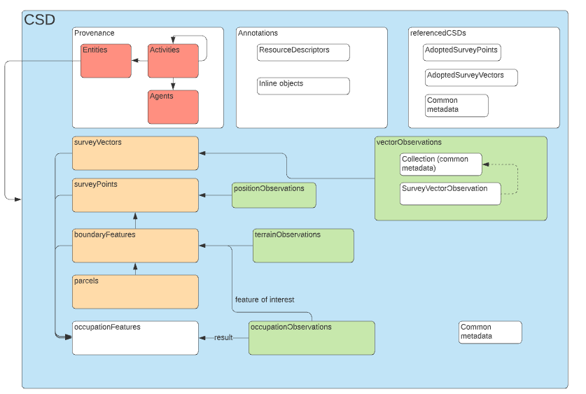
Canonical Examples
|
|
10.6. Conformance Class: Provenance Profile
10.6.1. Class: Cadastral Surveyor
An identified agent licensed to undertake cadastral surveys.
Subclass of
-
SurveyAgent (From Provenance Profile )
10.6.2. Class: Survey Activity
Entities, Activities and Agents for Cadastral Survey Data Exchange Activities.
10.6.3. Class: Survey CSD Lifecycle Activity
An activity in the lifecycle of a survey
Subclass of
-
Activity (From W3C PROVenance Interchange Ontology (PROV-O) )
-
Survey Activity (From Provenance Profile )
Properties
| Property | Description | Cardinality | Range | Use Case Requirement |
|---|---|---|---|---|
|
from Activity |
[0..*] |
|||
|
from Activity |
[0..*] |
|||
|
from Activity |
[0..*] |
|||
|
from Activity |
[0..*] |
|||
|
from Activity |
[0..*] |
|||
|
from Activity |
[0..*] |
|||
|
from Activity |
[0..*] |
|||
|
from Activity |
[0..*] |
|||
|
from Activity |
[0..*] |
|||
|
from Activity |
[0..*] |
|||
|
from Activity |
[0..*] |
|||
|
from Activity |
[0..*] |
|||
|
from Activity |
[0..*] |
|||
|
from Activity |
[0..*] |
|||
|
from Activity |
[0..*] |
|||
|
from Activity |
[0..*] |
|||
|
from Activity |
[0..*] |
|||
|
from Activity |
The object is a rule entity used to infer additional information and add to the generated object |
[0..*] |
||
|
from Activity |
Transformed With |
[0..*] |
||
|
from Activity |
Used configuration |
[0..*] |
||
|
from Activity |
Used Inferencing Rules |
[0..*] |
||
|
from Activity |
Used Data Source |
[0..*] |
||
|
from Activity |
User invoking activity |
[1..*] |
||
|
from Activity |
Validated With |
[0..*] |
Canonical Examples
|
|
|
|
10.6.4. Class: SurveyAgent
PROV Agent types
Subclass of
-
Agent (From W3C PROVenance Interchange Ontology (PROV-O) )
-
Survey Activity (From Provenance Profile )
10.6.5. Class: SurveyEntity
A data object influenced by a SurveyActivity, such as a Cadastral Survey Dataset (CSD)
Subclass of
-
Entity (From W3C PROVenance Interchange Ontology (PROV-O) )
-
Survey Activity (From Provenance Profile )
Properties
| Property | Description | Cardinality | Range | Use Case Requirement |
|---|---|---|---|---|
|
from Entity |
[0..*] |
|||
|
from Entity |
[0..*] |
|||
|
from Entity |
Generated at date or datetime |
[0..*] |
||
|
from Entity |
[0..*] |
|||
|
from Entity |
[0..*] |
|||
|
from Entity |
[0..*] |
|||
|
from Entity |
[0..*] |
|||
|
from Entity |
[0..*] |
|||
|
from Entity |
[0..*] |
|||
|
from Entity |
[0..*] |
|||
|
from Entity |
[0..*] |
|||
|
from Entity |
[0..*] |
|||
|
from Entity |
[0..*] |
|||
|
from Entity |
[0..*] |
|||
|
from Entity |
[0..*] |
|||
|
from Entity |
[0..*] |
|||
|
from Entity |
[0..*] |
|||
|
from Entity |
[0..*] |
|||
|
from Entity |
[0..*] |
|||
|
from Entity |
[0..*] |
|||
|
from Entity |
[0..*] |
|||
|
from Entity |
[0..*] |
10.7. Conformance Class: Survey Features
10.7.1. Class: Adopted Vector
A vector included in a CSD that has previously been observed and included in an existing CSD or Survey Plan.
Subclass of
-
SurveyedVector (From Survey Features )
Properties
| Property | Description | Cardinality | Range | Use Case Requirement |
|---|---|---|---|---|
|
from Feature |
hasGeometry property inherited from geo:Feature |
[0..*] |
||
|
from Surveyed Vector |
Distance |
[0..*] |
||
|
from Surveyed Vector |
[1] |
|||
|
from Surveyed Vector |
[0..*] |
|||
|
from Surveyed Vector |
[1] |
|||
|
from Surveyed Vector |
the horizontal angle of the target point relative to the ??? setup bearing ??? |
[0..*] |

Canonical Examples
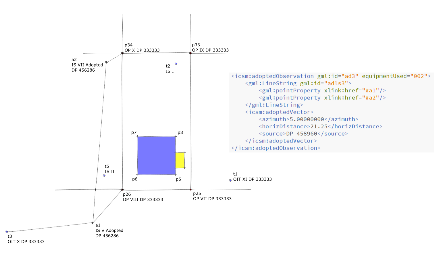
|
Informative Examples
xpath = /LandXML/Survey/
<ObservationGroup id="aa1">
<ReducedObservation
setupID="a1107" azimuth="277.07"
horizDistance="6.3" equipmentUsed="unknown"
azimuthType="adopted" distanceType="adopted"
azimuthAccClass="A" distanceAccClass="A"
adoptedAzimuthSurvey="DP 333333"
adoptedDistanceSurvey="DP 333333"
azimuthAdoptionFactor="0">
<TargetPoint pntRef="108" pointGeometry="point"/>
</ReducedObservation>
</ObservationGroup>
|
Title |
AdoptedObservations-12D |
|
Conforms To |
LandXML (proprietary) |
Show Details |
|
xpath = /LandXML/Survey/
<ObservationGroup id="OG-1">
<ReducedObservation
adoptedSurvey=DP 333333
name="15" desc="Connection"
setupID="IS14" targetSetupID="IS15"
azimuth="59.3032" horizDistance="324.525"
distanceType="Adopted"
azimuthType="Adopted"
coordGeomRefs="LOT-103">
<FieldNote></FieldNote>
<ReducedObservation />
</ObservationGroup>
|
Title |
AdoptedObservations-ePlanNSW |
|
Conforms To |
ePlan NSW |
Show Details |
|
10.7.2. Class: Boundary Mark
Means a location that defines a boundary corner or boundary alignment. The location will be physically marked unless the location is obstructed by a structure that can not be marked.
A boundary mark MAY be a Geodetic Reference Mark.
Subclass of
-
Survey Mark (From Survey Features )
Properties
| Property | Description | Cardinality | Range | Use Case Requirement |
|---|---|---|---|---|
|
from Survey Point |
[1] |
|||
|
from Survey Point, Feature |
Note that a Survey Point may not have a geometry declared - it may be identified and described and its location determined at a future date. hasGeometry property inherited from geo:Feature |
[0..1] |
||
|
from Survey Mark |
[1] |
|||
|
from Survey Point |
Provenance |
[1] |
||
|
from Survey Point |
[1] |
|||
|
from Survey Mark |
[1] |
Canonical Examples
|
|
Informative Examples
xpath = /LandXML/Survey/
<SurveyMonument
mntRef="OP VII DP 333333"
purpose="boundary defined by survey"
state="original"/>
xpath = /LandXML/Monuments/
<Monument
name="OP VII DP 333333" pntRef="109"
desc="OP VII DP 333333" type="peg"
condition="reliable" oID="8353475"/>
xpath = /LandXML/CgPoint/
<CgPoint
name="109" pntSurv="monument"
oID="3748446">
786033.6613 427102.5793
</CgPoint>
|
Title |
Boundary Mark |
|
Conforms To |
LandXML (proprietary) |
Show Details |
|
xpath=/LandXML/Monuments/
<Monument
name="1" pntRef="109"
type="Peg" state="Found"
desc="Original lot peg" condition="Remains"
originSurvey=OP VII DP 333333"/>
xpath=/LandXML/CgPoints/
<CgPoint
name="109" desc="A"
state=existing" pntSurv="boundary"
oID="8353475">
786033.66 427102.58 72.20
</CgPoint>
|
Title |
Boundary Mark ePlanNSW |
|
Conforms To |
ePlan NSW |
Show Details |
|
IfcCartesianPoint
type=TRAVERSE MARK
Properties - Coordinates, Monument Type,
Monument State, Monument Condition
|
Title |
BoundaryMark-IFC |
|
Conforms To |
IFC Version 4.3 |
Show Details |
|
xpath=/LandInfraDataset/feature/
<SurveyMonument gml:id="sm">
<type
xlink:href http://example.com/SurveyMonumentType#boundaryMark"
xlink:title "boundaryMark"/>
<documentation xlink:href "st1"/>
<spatialRepresentation>
<SpatialRepresentation>
<geometry>
<gml:Point gml:id="p1">
<gml:pos>786033.66 427102.58 72.20 </gml:pos>
</gml:Point>
</geometry>
</SpatialRepresentation>
</spatialRepresentation>
</SurveyMonument>
|
Title |
BoundaryMark-InfraGML |
|
Conforms To |
InfraGML Part 7 Land Division |
Show Details |
|
<LA_Point
LA_PointType=Source (Boundary?
)>
</LA_Point>
|
Title |
BoundaryMark-LADM |
|
Conforms To |
ISO19152-2 Surveying |
Show Details |
|
10.7.3. Class: Cadastral Feature
This is an abstract feature to identify elements of the Cadastral Survey Conceptual Model
Subclass of
-
Feature (From GeoSPARQL Vocabulary )
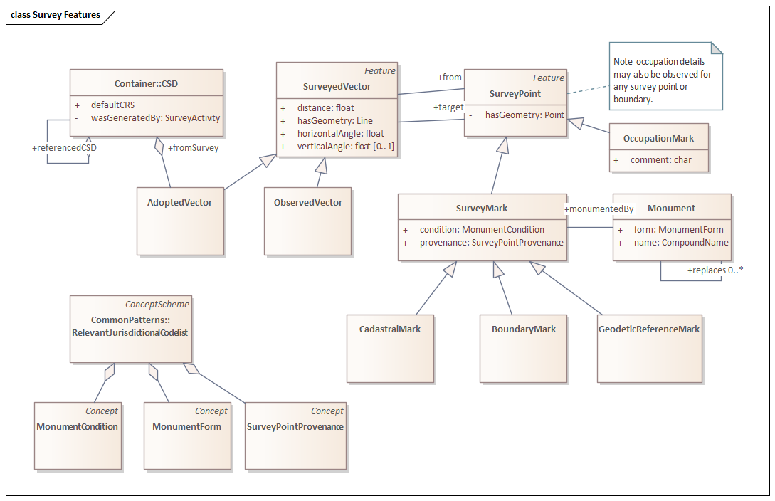
10.7.4. Class: Cadastral Mark
Any survey mark placed or observed as part of a cadastral survey that is not a boundary mark or a geodetic reference mark
Subclass of
-
Survey Mark (From Survey Features )
Properties
| Property | Description | Cardinality | Range | Use Case Requirement |
|---|---|---|---|---|
|
from Survey Point |
[1] |
|||
|
from Survey Point, Feature |
Note that a Survey Point may not have a geometry declared - it may be identified and described and its location determined at a future date. hasGeometry property inherited from geo:Feature |
[0..1] |
||
|
from Survey Mark |
[1] |
|||
|
from Survey Point |
Provenance |
[1] |
||
|
from Survey Point |
[1] |
|||
|
from Survey Mark |
[1] |
Canonical Examples
|
|
Informative Examples
xpath=/LandInfraDataset/feature/
<SurveyMonument gml:id="sm">
<type
xlink:href http://example.com/SurveyMonumentType#siteMark"
xlink:title "siteMark"/>
<documentation xlink:href "st2"/>
<spatialRepresentation>
<SpatialRepresentation>
<geometry>
<gml:Point gml:id=p2">
<gml:pos> 786030.41 427103.14 71.95 </gml:pos>
</gml:Point>
</geometry>
</SpatialRepresentation>
</spatialRepresentation>
</SurveyMonument>
|
Title |
CadasralMark-InfraGML |
|
Conforms To |
InfraGML Part 7 Land Division |
Show Details |
|
xpath = /LandXML/Survey/
<SurveyMonument
mntRef="OIT XI DP 333333"
purpose="non boundary"
state="original"/>
xpath = /LandXML/Monuments/
<Monument
name="OIT XI DP 333333" pntRef="102"
desc="OIT XI DP 333333" type="tube"
condition="reliable" oID="2189349"/>
xpath = /LandXML/CgPoint/
<CgPoint
name="102" pntSurv="monument"
oID="2730030">
786030.4096 427103.14
</CgPoint>
|
Title |
CadastralMark-12D |
|
Conforms To |
LandXML (proprietary) |
Show Details |
|
|
Title |
CadastralMark-LADM |
Show Details |
|
xpath=/LandXML/CgPoints/
<CgPoint
name="101" desc="A"
state=existing" pntSurv=control"
oID="5828822">
785961.64 427088.01 72.46
</CgPoint>
xpath=/LandXML/Monuments/
<Monument
name="OIT X DP 333333" pntRef="101"
type="Peg" state="Found"
desc="Original lot peg" condition="Remains"
originSurvey="OIT X DP 33333"
</Monument>
|
Title |
CadastralMarks-ePlanNSW |
|
Conforms To |
ePlan NSW |
Show Details |
|
IfcCartesianPoint
type=REFERENCE MARK
Properties - Coordinates, Monument Type,
Monument State, Monument Condition
|
Title |
CadastralMarks-IFC |
|
Conforms To |
IFC Version 4.3 |
Show Details |
|
10.7.5. Class: Geodetic Reference Mark
Means a mark that connects a survey to the jurisdictional geodetic network, vertical or horizontal.
Subclass of
-
Survey Mark (From Survey Features )
Properties
| Property | Description | Cardinality | Range | Use Case Requirement |
|---|---|---|---|---|
|
from Survey Point |
[1] |
|||
|
from Survey Point, Feature |
Note that a Survey Point may not have a geometry declared - it may be identified and described and its location determined at a future date. hasGeometry property inherited from geo:Feature |
[0..1] |
||
|
from Survey Mark |
[1] |
|||
|
from Survey Point |
Provenance |
[1] |
||
|
from Survey Point |
[1] |
|||
|
from Survey Mark |
[1] |
Canonical Examples
|
|
Informative Examples
xpath = /LandXML/Survey/
<SurveyMonument
mntRef="OIT XI DP 333333"
purpose="non boundary"
state="original"/>
xpath = /LandXML/Monuments/
<Monument
name="OIT XI DP 333333" pntRef="102"
desc="OIT XI DP 333333" type="tube"
condition="reliable" oID="2189349"/>
xpath = /LandXML/CgPoint/
<CgPoint
name="102" pntSurv="monument"
oID="2730030">
786030.4096 427103.14
</CgPoint>
|
Title |
GeodeticMark-12D |
|
Conforms To |
LandXML (proprietary) |
Show Details |
|
xpath=/LandXML/CgPoints/
<CgPoint
name="101" desc="A"
state=existing" pntSurv=control"
oID="5828822">
785961.64 427088.01 72.46
</CgPoint>
xpath=/LandXML/Monuments/
<Monument
name="OIT X DP 333333" pntRef="101"
type="Peg" state="Found"
desc="Original lot peg" condition="Remains"
originSurvey="OIT X DP 33333"
</Monument>
|
Title |
GeodeticMark-ePlanNSW |
|
Conforms To |
ePlan NSW |
Show Details |
|
xpath=/LandInfraDataset/feature/
<SurveyMonument gml:id="sm">
<type
xlink:href http://example.com/SurveyMonumentType#trigonometricMark"
xlink:title "trigonometricMark"/>
<documentation xlink:href "st3"/>
<spatialRepresentation>
<SpatialRepresentation>
<geometry>
<gml:Point gml:id="p3">
<gml:pos> 785961.64 427088.01 72.46 </gml:pos>
</gml:Point>
</geometry>
</SpatialRepresentation>
</spatialRepresentation>
</SurveyMonument>
|
Title |
GeodeticMark-InfraGML |
|
Conforms To |
InfraGML Part 7 Land Division |
Show Details |
|
IfcCartesianPoint
type=SURVEY MARK (?)
Properties - OID, Coordinates, Monument Type,
Monument State, Monument Condition
|
Title |
GeodeticMarks-IFC |
|
Conforms To |
IFC Version 4.3 |
Show Details |
|
10.7.6. Class: Monument
An object that is placed in the ground, or referred to, for the purpose of identifying a survey point in a cadastral survey.
Subclass of
-
Cadastral Feature (From Survey Features )
Properties
| Property | Description | Cardinality | Range | Use Case Requirement |
|---|---|---|---|---|
|
from Feature |
hasGeometry property inherited from geo:Feature |
[0..*] |
||
|
from Monument |
[0..*] |
|||
|
from Monument |
Monument Physical Form |
[1..*] |
||
|
from Monument |
[0..*] |
Canonical Examples
|
|
Informative Examples
|
Title |
Monument-12d |
Show Details |
|
xpath=/LandXML/Monuments/ <Monument name="30" pntRef="5" type="Occupation" state="Found" desc="1.00 Clear Smith Rd, 0.05 Clear Fred St"/>
|
Title |
Monument-ePlanNSW |
Show Details |
|
|
Title |
Monument-LADM |
Show Details |
|
10.7.7. Class: Observed Vector
A vector consisting of one or more reduced and/or adjusted observed measurements. Observations may include calculation procedures.
Subclass of
-
SurveyedVector (From Survey Features )
Properties
| Property | Description | Cardinality | Range | Use Case Requirement |
|---|---|---|---|---|
|
from Feature |
hasGeometry property inherited from geo:Feature |
[0..*] |
||
|
from Surveyed Vector |
Distance |
[0..*] |
||
|
from Surveyed Vector |
[1] |
|||
|
from Surveyed Vector |
[0..*] |
|||
|
from Surveyed Vector |
[1] |
|||
|
from Surveyed Vector |
the horizontal angle of the target point relative to the ??? setup bearing ??? |
[0..*] |

Canonical Examples
|
Description |
The angle and distance properties of this feature are derived from individual observations, the geometry is derived from the calculated locations of instrument and target points. |
|
ISO-10303-21;
HEADER;
FILE_SCHEMA(('IFC4'));
ENDSEC;
DATA;
/* site / project level information - mostly boilerplate*/
#11=IFCPROJECT('1Pv7U_QXf86vJbLHc6LgdI',$,'Project',$,$,$,$,(#20,#27),#15);
#12=IFCSIUNIT(*,.LENGTHUNIT.,$,.METRE.);
#13=IFCSIUNIT(*,.AREAUNIT.,$,.SQUARE_METRE.);
#14=IFCSIUNIT(*,.VOLUMEUNIT.,$,.CUBIC_METRE.);
#15=IFCUNITASSIGNMENT((#12,#13,#14));
#16=IFCCARTESIANPOINT((0.,0.,0.));
#17=IFCDIRECTION((0.,0.,1.));
#18=IFCDIRECTION((1.,0.,0.));
#19=IFCAXIS2PLACEMENT3D(#16,#17,#18);
#20=IFCGEOMETRICREPRESENTATIONCONTEXT($,'Model',3,1.E-05,#19,$);
#21=IFCGEOMETRICREPRESENTATIONSUBCONTEXT('Body','Model',*,*,*,*,#20,$,.MODEL_VIEW.,$);
#22=IFCGEOMETRICREPRESENTATIONSUBCONTEXT('Box','Model',*,*,*,*,#20,$,.MODEL_VIEW.,$);
#23=IFCCARTESIANPOINT((0.,0.,0.));
#24=IFCDIRECTION((0.,0.,1.));
#25=IFCDIRECTION((1.,0.,0.));
#26=IFCAXIS2PLACEMENT3D(#23,#24,#25);
#27=IFCGEOMETRICREPRESENTATIONCONTEXT($,'Plan',2,1.E-05,#26,$);
#32=IFCSITE('1KBmulBMf7MgB4kkr2pyT$',$,'Site',$,$,#47,$,$,$,$,$,$,$,$);
#34=IFCRELAGGREGATES('0MyLGeOvDDiQIJV8BnTpRw',$,$,$,#11,(#32));
#36=IFCBUILDING('23JhBYRQDDjws2fDYl7eZ5',$,'Building',$,$,#52,$,$,$,$,$,$);
#38=IFCRELAGGREGATES('0MyLGeOvDDiQIJV8BnTpRw',#37,$,$,#32,(#36));
#40=IFCBUILDINGSTOREY('23JhBYRQDDjws2fDYl7eZ5',$,'Building Storey',$,$,#52,$,$,$,$,$,$);
#42=IFCRELAGGREGATES('0MyLGeOvDDiQIJV8BnTpRw',$,$,$,#36,(#40));
#43=IFCCARTESIANPOINT((0.,0.,0.));
#44=IFCDIRECTION((0.,0.,1.));
#45=IFCDIRECTION((1.,0.,0.));
#46=IFCAXIS2PLACEMENT3D(#43,#44,#45);
#47=IFCLOCALPLACEMENT($,#46);
#48=IFCCARTESIANPOINT((0.,0.,0.));
#49=IFCDIRECTION((0.,0.,1.));
#50=IFCDIRECTION((1.,0.,0.));
#51=IFCAXIS2PLACEMENT3D(#48,#49,#50);
#52=IFCLOCALPLACEMENT(#47,#51);
/* IFC object definitions */
/* Traverse Points */
/* survey marker style material definition */
#809=IFCCOLOURRGB($,0.,0.,0.);
#810=IFCCOLOURRGB($,0.,0.,0.);
#811=IFCSURFACESTYLERENDERING(#809 ,0.,#810,$,$,$,$,$,.NOTDEFINED.);
#812=IFCSURFACESTYLE('Survey Marker Black',.BOTH.,(#811));
/* survey marker style material definition */
#813=IFCCOLOURRGB($,1.,0.,0.);
#814=IFCCOLOURRGB($,1.,0.,0.);
#815=IFCSURFACESTYLERENDERING(#813 ,0.,#814,$,$,$,$,$,.NOTDEFINED.);
#816=IFCSURFACESTYLE('Traverse Marker Red',.BOTH.,(#815));
/* survey observation style material to show the survey arc from horizontal plane to observation target */
#817=IFCCOLOURRGB($,0.0,0.,1.);
#818=IFCCOLOURRGB($,0.0,0.,1.);
#819=IFCSURFACESTYLERENDERING(#817 ,0.5,#818,$,$,$,$,$,.NOTDEFINED.);
#820=IFCSURFACESTYLE('Survey Observation Shot Style',.BOTH.,(#819));
/* traverse observation style material to show the survey arc from horizontal plane to observation target */
#821=IFCCOLOURRGB($,1.0,0.,0.);
#822=IFCCOLOURRGB($,1.0,0.,0.);
#823=IFCSURFACESTYLERENDERING(#821 ,0.,#822,$,$,$,$,$,.NOTDEFINED.);
#824=IFCSURFACESTYLE('Traverse Observation Shot Style',.BOTH.,(#823));
/* survey/traverse/occupation marker object - this is a cube */
#825=IFCINDEXEDPOLYGONALFACE((2,4,1));
#826=IFCINDEXEDPOLYGONALFACE((6,8,5));
#827=IFCINDEXEDPOLYGONALFACE((2,7,3));
#828=IFCINDEXEDPOLYGONALFACE((4,5,1));
#829=IFCINDEXEDPOLYGONALFACE((3,6,4));
#830=IFCINDEXEDPOLYGONALFACE((1,8,2));
#831=IFCINDEXEDPOLYGONALFACE((2,3,4));
#832=IFCINDEXEDPOLYGONALFACE((6,7,8));
#833=IFCINDEXEDPOLYGONALFACE((2,8,7));
#834=IFCINDEXEDPOLYGONALFACE((4,6,5));
#835=IFCINDEXEDPOLYGONALFACE((3,7,6));
#836=IFCINDEXEDPOLYGONALFACE((1,5,8));
#837=IFCCARTESIANPOINTLIST3D(((-0.1,0.1,0.1),(-0.1,-0.1,0.1),(0.1,-0.1,0.1),(0.1,0.1,0.1),(-0.1,0.1,-0.1),(0.1,0.1,-0.1),(0.1,-0.1,-0.1),(-0.1,-0.1,-0.1)));
#838=IFCPOLYGONALFACESET(#837,$,(#825,#826,#827,#828,#829,#830,#831,#832,#833,#834,#835,#836),$);
#839=IFCSHAPEREPRESENTATION(#21,'Body','Tessellation',(#838));
/* traverse point definitions */
#841=IFCGEOGRAPHICELEMENT('0000000000P1',$,'T1','Survey Point - Traverse T1 - ShowLabel',$,#846,#850,$,.USERDEFINED.);
#842=IFCCARTESIANPOINT((50.36, -37.37, -0.22));
#843=IFCDIRECTION((0.,0.,1.));
#844=IFCDIRECTION((1.,0.,0.));
#845=IFCAXIS2PLACEMENT3D(#842,#843,#844);
#846=IFCLOCALPLACEMENT($,#845);
#847=IFCCARTESIANPOINT((50.16, -37.57, -0.42));
#848=IFCBOUNDINGBOX(#847, 0.2,0.2,0.2);
#849=IFCSHAPEREPRESENTATION(#22,'Box','BoundingBox',(#848));
#850=IFCPRODUCTDEFINITIONSHAPE($,$,(#849,#839));
#851=IFCSTYLEDITEM(#841,(#816),'Traverse Marker Red');
#853=IFCGEOGRAPHICELEMENT('0000000000P1',$,'T2','Survey Point - Traverse T2 - ShowLabel',$,#858,#862,$,.USERDEFINED.);
#854=IFCCARTESIANPOINT((43.19, -21.98, -1.84));
#855=IFCDIRECTION((0.,0.,1.));
#856=IFCDIRECTION((1.,0.,0.));
#857=IFCAXIS2PLACEMENT3D(#854,#855,#856);
#858=IFCLOCALPLACEMENT($,#857);
#859=IFCCARTESIANPOINT((42.99, -22.18, -2.04));
#860=IFCBOUNDINGBOX(#859, 0.2,0.2,0.2);
#861=IFCSHAPEREPRESENTATION(#22,'Box','BoundingBox',(#860));
#862=IFCPRODUCTDEFINITIONSHAPE($,$,(#861,#839));
#863=IFCSTYLEDITEM(#853,(#816),'Traverse Marker Red');
#865=IFCGEOGRAPHICELEMENT('0000000000P1',$,'T3','Survey Point - Traverse T3 - ShowLabel',$,#870,#874,$,.USERDEFINED.);
#866=IFCCARTESIANPOINT((20.82, -44.15, 0.7));
#867=IFCDIRECTION((0.,0.,1.));
#868=IFCDIRECTION((1.,0.,0.));
#869=IFCAXIS2PLACEMENT3D(#866,#867,#868);
#870=IFCLOCALPLACEMENT($,#869);
#871=IFCCARTESIANPOINT((20.62, -44.35, 0.5));
#872=IFCBOUNDINGBOX(#871, 0.2,0.2,0.2);
#873=IFCSHAPEREPRESENTATION(#22,'Box','BoundingBox',(#872));
#874=IFCPRODUCTDEFINITIONSHAPE($,$,(#873,#839));
#875=IFCSTYLEDITEM(#865,(#816),'Traverse Marker Red');
#965=IFCGEOGRAPHICELEMENT('0000000000P1',$,'T5 ','Survey Point - Traverse T5 - ShowLabel',$,#970,#974,$,.USERDEFINED.);
#966=IFCCARTESIANPOINT((33.699, -36.720, -0.050));
#967=IFCDIRECTION((0.,0.,1.));
#968=IFCDIRECTION((1.,0.,0.));
#969=IFCAXIS2PLACEMENT3D(#966,#967,#968);
#970=IFCLOCALPLACEMENT($,#969);
#971=IFCCARTESIANPOINT((20.62, -44.35, 0.5));
#972=IFCBOUNDINGBOX(#971, 0.2,0.2,0.2);
#973=IFCSHAPEREPRESENTATION(#22,'Box','BoundingBox',(#972));
#974=IFCPRODUCTDEFINITIONSHAPE($,$,(#973,#839));
#975=IFCSTYLEDITEM(#965,(#816),'Traverse Marker Red');
/* traverse side shot package */
/* t1 - t2 shot */
#877=IFCGEOGRAPHICELEMENT('0IF3fpCFX3ogRh9fQ1IcS5',$,'T1 - T2 Traverse |Azimuth: 335.02 |Zenith: 95.45 |Distance: 17.06','Survey Shot T1-T2 - ',$,#882,#890,$,.TERRAIN.);
#878=IFCCARTESIANPOINT((0.,0.,-0.1));
#879=IFCDIRECTION((0.,0.,1.));
#880=IFCDIRECTION((1.,0.,0.));
#881=IFCAXIS2PLACEMENT3D(#878,#879,#880);
#882=IFCLOCALPLACEMENT($,#881);
#883=IFCINDEXEDPOLYGONALFACE((1,2,3));
#884=IFCCARTESIANPOINTLIST3D(((50.36, -37.37, -0.22),(43.19, -21.98, -1.84),(43.19, -21.98, -1.94)));
#885=IFCPOLYGONALFACESET(#884,$,(#883),$);
#886=IFCSHAPEREPRESENTATION(#21,'Body','Tessellation',(#885));
#887=IFCCARTESIANPOINT((36.0890007019043,-38.5764923095703,-1.75192153453827));
#888=IFCBOUNDINGBOX(#887, 2.,5.,5.6);
#889=IFCSHAPEREPRESENTATION(#22,'Box','BoundingBox',(#888));
#890=IFCPRODUCTDEFINITIONSHAPE($,$,(#889,#886));
#891=IFCSTYLEDITEM(#877,(#824),'Traverse Observation Shot Style');
/* t1 - t3 shot */
#904=IFCGEOGRAPHICELEMENT('0IF3fpCFX3ogRh9fQ1IcS5',$,'T1 - T3 Traverse |Azimuth: 257.08 |Zenith: 88.26 |Distance: 30.32','Survey Shot T1-T3 - ',$,#909,#917,$,.TERRAIN.);
#905=IFCCARTESIANPOINT((0.,0.,-0.1));
#906=IFCDIRECTION((0.,0.,1.));
#907=IFCDIRECTION((1.,0.,0.));
#908=IFCAXIS2PLACEMENT3D(#905,#906,#907);
#909=IFCLOCALPLACEMENT($,#908);
#910=IFCINDEXEDPOLYGONALFACE((1,2,3));
#911=IFCCARTESIANPOINTLIST3D(((50.36, -37.37, -0.22),(20.82, -44.15, 0.7),(20.82, -44.15, 0.8)));
#912=IFCPOLYGONALFACESET(#911,$,(#910),$);
#913=IFCSHAPEREPRESENTATION(#21,'Body','Tessellation',(#912));
#914=IFCCARTESIANPOINT((50.36, -37.37, -0.22));
#915=IFCBOUNDINGBOX(#914, 2.,5.,5.6);
#916=IFCSHAPEREPRESENTATION(#22,'Box','BoundingBox',(#915));
#917=IFCPRODUCTDEFINITIONSHAPE($,$,(#916,#913));
#918=IFCSTYLEDITEM(#904,(#824),'Traverse Observation Shot Style');
#1036=IFCGEOGRAPHICELEMENT('0000000000P3',$,'P3','Survey Point P3 - ShowLabel',$,#1041,#1046,$,.USERDEFINED.);
#1037=IFCCARTESIANPOINT((43.089, -36.596, 5.000));
#1038=IFCDIRECTION((0.,0.,1.));
#1039=IFCDIRECTION((1.,0.,0.));
#1040=IFCAXIS2PLACEMENT3D(#1037,#1038,#1039);
#1041=IFCLOCALPLACEMENT($,#1040);
#1042=IFCCARTESIANPOINT((42.889, -36.396, 4.8));
#1043=IFCBOUNDINGBOX(#1042 ,0.2,0.2,0.2);
#1045=IFCSHAPEREPRESENTATION(#22,'Box','BoundingBox',(#1043));
#1046=IFCPRODUCTDEFINITIONSHAPE($,$,(#1045,#839));
#1047=IFCSTYLEDITEM(#1036,(#812),'Survey Marker Black');
/* t5 - t3 shot */
#1049=IFCGEOGRAPHICELEMENT('0IF3fpCFX3ogRh9fQ1IcS5',$,'T5 - T3 ','Traverse Shot T5-T3 - ',$,#1054,#1062,$,.TERRAIN.);
#1050=IFCCARTESIANPOINT((0.,0.,-0.1));
#1051=IFCDIRECTION((0.,0.,1.));
#1052=IFCDIRECTION((1.,0.,0.));
#1053=IFCAXIS2PLACEMENT3D(#1050,#1051,#1052);
#1054=IFCLOCALPLACEMENT($,#1053);
#1055=IFCINDEXEDPOLYGONALFACE((1,2,3));
#1056=IFCCARTESIANPOINTLIST3D(((33.699, -36.720, -0.050),(20.82, -44.15, 0.7),(20.82, -44.15, 0.8)));
#1057=IFCPOLYGONALFACESET(#1056,$,(#1055),$);
#1058=IFCSHAPEREPRESENTATION(#21,'Body','Tessellation',(#1057));
#1059=IFCCARTESIANPOINT((50.36, -37.37, -0.22));
#1060=IFCBOUNDINGBOX(#1059, 2.,5.,5.6);
#1061=IFCSHAPEREPRESENTATION(#22,'Box','BoundingBox',(#1060));
#1062=IFCPRODUCTDEFINITIONSHAPE($,$,(#1061,#1058));
#1063=IFCSTYLEDITEM(#1049,(#824),'Traverse Observation Shot Style');
/* t2 - t5 shot */
#11049=IFCGEOGRAPHICELEMENT('0IF3fpCFX3ogRh9fQ1IcS5',$,'T2 - T5 ','Traverse Shot T2-T5 - ',$,#11054,#11062,$,.TERRAIN.);
#11050=IFCCARTESIANPOINT((0.,0.,-0.1));
#11051=IFCDIRECTION((0.,0.,1.));
#11052=IFCDIRECTION((1.,0.,0.));
#11053=IFCAXIS2PLACEMENT3D(#11050,#11051,#11052);
#11054=IFCLOCALPLACEMENT($,#11053);
#11055=IFCINDEXEDPOLYGONALFACE((1,2,3));
#11056=IFCCARTESIANPOINTLIST3D(((43.19, -21.98, -1.84),(33.699, -36.720, -0.050),(33.699, -36.720, 0.050)));
#11057=IFCPOLYGONALFACESET(#11056,$,(#11055),$);
#11058=IFCSHAPEREPRESENTATION(#21,'Body','Tessellation',(#11057));
#11059=IFCCARTESIANPOINT((50.36, -37.37, -0.22));
#11060=IFCBOUNDINGBOX(#11059, 2.,5.,5.6);
#11061=IFCSHAPEREPRESENTATION(#22,'Box','BoundingBox',(#11060));
#11062=IFCPRODUCTDEFINITIONSHAPE($,$,(#11061,#11058));
#11063=IFCSTYLEDITEM(#11049,(#824),'Traverse Observation Shot Style');
#1093=IFCOWNERHISTORY(#9,#8,.READWRITE.,.MODIFIED.,1638903018,#9,#8,1638903018);
#1094=IFCGEOGRAPHICELEMENT('0000000000P25',#1093,'P25','Survey Point P25 - ShowLabel',$,#1099,#1103,$,.USERDEFINED.);
#1095=IFCCARTESIANPOINT((45.089, -38.596, -0.1000));
#1096=IFCDIRECTION((0.,0.,1.));
#1097=IFCDIRECTION((1.,0.,0.));
#1098=IFCAXIS2PLACEMENT3D(#1095,#1096,#1097);
#1099=IFCLOCALPLACEMENT($,#1098);
#1100=IFCCARTESIANPOINT((44.889, -38.396, -0.300));
#1101=IFCBOUNDINGBOX(#1100 ,0.2,0.2,0.2);
#1102=IFCSHAPEREPRESENTATION(#22,'Box','BoundingBox',(#1101));
#1103=IFCPRODUCTDEFINITIONSHAPE($,$,(#1102,#839));
#8851=IFCSTYLEDITEM(#1094,(#812),'Traverse Marker Black');
#1873=IFCOWNERHISTORY(#9,#8,.READWRITE.,.MODIFIED.,1638903018,#9,#8,1638903018);
#1874=IFCGEOGRAPHICELEMENT('0000000000P5',#1873,'P5','Survey Point P5 - ShowLabel',$,#1879,#1883,$,.USERDEFINED.);
#1875=IFCCARTESIANPOINT((43.089, -36.596, 0.300));
#1876=IFCDIRECTION((0.,0.,1.));
#1877=IFCDIRECTION((1.,0.,0.));
#1878=IFCAXIS2PLACEMENT3D(#1875,#1876,#1877);
#1879=IFCLOCALPLACEMENT($,#1878);
#1880=IFCCARTESIANPOINT((42.889, -36.396, 0.100));
#1881=IFCBOUNDINGBOX(#1880 ,0.2,0.2,0.2);
#1882=IFCSHAPEREPRESENTATION(#22,'Box','BoundingBox',(#1881));
#1883=IFCPRODUCTDEFINITIONSHAPE($,$,(#1882,#839));
#8852=IFCSTYLEDITEM(#1874,(#812),'Traverse Marker Black');
/* t1 - p25 shot */
/* (Azimuth: 276.08, Zenith: 54.48, Dist: 8.98) */
#2009=IFCGEOGRAPHICELEMENT('0IF3fpCFX3ogRh9fQ1IcS5',$,'T1 -> P25 |Side Shot Observation ||Azimuth: 256.90 deg. |Zenith: 88.733 deg. |Distance: 5.413 m ||Angular Error: +/- 0.049722 deg. |Distance Error: +/- 0.010 m','Survey Shot T1-P25 - ',$,#2014,#2022,$,.TERRAIN.);
#2010=IFCCARTESIANPOINT((0.,0.,-0.1));
#2011=IFCDIRECTION((0.,0.,1.));
#2012=IFCDIRECTION((1.,0.,0.));
#2013=IFCAXIS2PLACEMENT3D(#2010,#2011,#2012);
#2014=IFCLOCALPLACEMENT($,#2013);
#2015=IFCINDEXEDPOLYGONALFACE((1,2,3));
#2016=IFCCARTESIANPOINTLIST3D(((50.36, -37.37, -0.22),(45.089, -38.596, -0.1000),(45.089, -38.596, -0.0000)));
#2017=IFCPOLYGONALFACESET(#2016,$,(#2015),$);
#2018=IFCSHAPEREPRESENTATION(#21,'Body','Tessellation',(#2017));
#2019=IFCCARTESIANPOINT((50.36, -37.37, -0.22));
#2020=IFCBOUNDINGBOX(#2019, 2.,5.,5.6);
#2021=IFCSHAPEREPRESENTATION(#22,'Box','BoundingBox',(#2020));
#2022=IFCPRODUCTDEFINITIONSHAPE($,$,(#2021,#2018));
#2023=IFCSTYLEDITEM(#2009,(#820),'Survey Observation Shot Style');
/* t1 - p5 shot */
/* (Azimuth: 276.08, Zenith: 54.48, Dist: 8.98) */
#3009=IFCGEOGRAPHICELEMENT('0IF3fpCFX3ogRh9fQ1IcS5',$,'T1 -> P5 |Side Shot Observation ||Azimuth: 281.61667 deg. |Zenith: 88.91667 deg. |Distance: 7.352 m ||Angular Error: +/- 0.06563086659 deg. |Distance Error: +/- 0.020 m','Survey Shot T1-P5 - ',$,#3014,#3022,$,.TERRAIN.);
#3010=IFCCARTESIANPOINT((0.,0.,-0.1));
#3011=IFCDIRECTION((0.,0.,1.));
#3012=IFCDIRECTION((1.,0.,0.));
#3013=IFCAXIS2PLACEMENT3D(#3010,#3011,#3012);
#3014=IFCLOCALPLACEMENT($,#3013);
#3015=IFCINDEXEDPOLYGONALFACE((1,2,3));
#3016=IFCCARTESIANPOINTLIST3D(((50.36, -37.37, -0.22),(43.089, -36.596, 0.300),(43.089, -36.596, 0.400)));
#3017=IFCPOLYGONALFACESET(#3016,$,(#3015),$);
#3018=IFCSHAPEREPRESENTATION(#21,'Body','Tessellation',(#3017));
#3019=IFCCARTESIANPOINT((50.36, -37.37, -0.22));
#3020=IFCBOUNDINGBOX(#3019, 2.,5.,5.6);
#3021=IFCSHAPEREPRESENTATION(#22,'Box','BoundingBox',(#3020));
#3022=IFCPRODUCTDEFINITIONSHAPE($,$,(#3021,#3018));
#3023=IFCSTYLEDITEM(#3009,(#820),'Survey Observation Shot Style');
/* p25 - p5 shot */
/* (Azimuth: 276.08, Zenith: 54.48, Dist: 8.98) */
#4009=IFCGEOGRAPHICELEMENT('0IF3fpCFX3ogRh9fQ1IcS5',$,'P25 -> P5 |Computed Vector ||Azimuth: 315.00 deg. |Zenith: 81.9500 deg. |Distance: 2.857 m ||Computed from |T1->P25 & T1->P5 Observations','Survey Shot P25-P5 - ShowLabel',$,#4014,#4022,$,.TERRAIN.);
#4010=IFCCARTESIANPOINT((0.,0.,-0.1));
#4011=IFCDIRECTION((0.,0.,1.));
#4012=IFCDIRECTION((1.,0.,0.));
#4013=IFCAXIS2PLACEMENT3D(#4010,#4011,#4012);
#4014=IFCLOCALPLACEMENT($,#4013);
#4015=IFCINDEXEDPOLYGONALFACE((1,2,3));
#4016=IFCCARTESIANPOINTLIST3D(((45.089, -38.596, -0.1000),(43.089, -36.596, 0.300),(43.089, -36.596, 0.500)));
#4017=IFCPOLYGONALFACESET(#4016,$,(#4015),$);
#4018=IFCSHAPEREPRESENTATION(#21,'Body','Tessellation',(#4017));
#4019=IFCCARTESIANPOINT((50.36, -37.37, -0.22));
#4020=IFCBOUNDINGBOX(#4019, 2.,5.,5.6);
#4021=IFCSHAPEREPRESENTATION(#22,'Box','BoundingBox',(#4020));
#4022=IFCPRODUCTDEFINITIONSHAPE($,$,(#4021,#4018));
#4023=IFCSTYLEDITEM(#4009,(#812),'Survey Observation Shot Style');
ENDSEC;
END-ISO-10303-21;
|
|
|
|
|
|
Informative Examples
xpath = /LandXML/Survey/
<ObservationGroup id="aa1">
<ReducedObservation
setupID="a1102" azimuth="103.0220"
horizDistance="122.54" equipmentUsed="theodolite EDM"
azimuthType="measured" distanceType="measured"
azimuthAccClass="A" distanceAccClass="A">
<TargetPoint pntRef="103" pointGeometry="point"/>
</ReducedObservation>
</ObservationGroup>
|
Title |
SurveyObservation-12D |
|
Conforms To |
LandXML (proprietary) |
Show Details |
|
xpath = /LandXML/Survey/
<ObservationGroup id="OG-1">
<ReducedObservation
name="15" desc="Connection"
setupID="IS14" targetSetupID="IS15"
azimuth="59.3032" horizDistance="324.525"
distanceType="Measured"
azimuthType="Measured"
distanceAdoptionFactor="1.00024000"
coordGeomRefs="LOT-103">
<FieldNote></FieldNote>
<ReducedObservation />
</ObservationGroup>
|
Title |
SurveyObservation-ePlanNSW |
|
Conforms To |
ePlan NSW |
Show Details |
|
IfcPolyline
Type=TRAVERSE LINE or RADIATION LINE
Properties=Equipment, Bearing, Distance
|
Title |
SurveyObservation-IFC |
|
Conforms To |
IFC Version 4.3 |
Show Details |
|
10.7.8. Class: Occupation Mark
Means a mark used for a cadastral survey to define the location of an occupation feature near a cadastral boundary.
|
Note
|
Occupation Marks are not monumented but may be described. Observed Vectors or Direct Position Observations determine the location of the mark. |
Subclass of
-
Survey Point (From Survey Features )
Properties
| Property | Description | Cardinality | Range | Use Case Requirement |
|---|---|---|---|---|
|
from Survey Point |
[1] |
|||
|
from Survey Point, Feature |
Note that a Survey Point may not have a geometry declared - it may be identified and described and its location determined at a future date. hasGeometry property inherited from geo:Feature |
[0..1] |
||
|
from Occupation Feature |
[0..*] |
|||
|
from Occupation Feature |
Estimated Age |
[0..1] |
||
|
from Survey Point |
Provenance |
[1] |
||
|
from Survey Point |
[1] |
Canonical Examples
|
Description |
age 5 yrs |
|
|
|
Informative Examples
xpath=/LandXML/CgPoints/
<CgPoint name="5" state="existing" pntSurv="sideshot">
1153.054100 958.694270
</CgPoint>
xpath=/LandXML/Monuments/
<Monument name="30" pntRef="5" type="Occupation" state="Found" desc="1.00 Clear Smith Rd, 0.05 Clear Fred St"/>
|
Title |
Occupation-ePlanNSW |
|
Conforms To |
ePlan NSW |
Show Details |
|
IfcPolyline
Type=OCCUPATION
Properties - Type, Description
|
Title |
OccupationObservations-IFC |
|
Conforms To |
IFC Version 4.3 |
Show Details |
|
10.7.9. Class: Survey Mark
A SurveyMark is a physically located object which by its form defines a point on the surface of the Earth and which is stable during surveying operations.
|
Note
|
The purpose of the mark is relative the CSD - so the same identified object may have different types in different CSDs - in which case how does the aggregated data record the purpose? |
Subclass of
-
Survey Point (From Survey Features )
Properties
| Property | Description | Cardinality | Range | Use Case Requirement |
|---|---|---|---|---|
|
from Survey Point |
[1] |
|||
|
from Survey Point, Feature |
Note that a Survey Point may not have a geometry declared - it may be identified and described and its location determined at a future date. hasGeometry property inherited from geo:Feature |
[0..1] |
||
|
from Survey Mark |
[1] |
|||
|
from Survey Point |
Provenance |
[1] |
||
|
from Survey Point |
[1] |
|||
|
from Survey Mark |
[1] |

Canonical Examples
|
|
10.7.10. Class: Survey Point
Any point of interest in a survey. It may relate to a boundary corner (marked or unmarked), a cadastral mark, a geodetic reference mark, or an occupation mark.
Subclass of
-
Cadastral Feature (From Survey Features )
Properties
| Property | Description | Cardinality | Range | Use Case Requirement |
|---|---|---|---|---|
|
from Survey Point |
[1] |
|||
|
from Survey Point, Feature |
Note that a Survey Point may not have a geometry declared - it may be identified and described and its location determined at a future date. hasGeometry property inherited from geo:Feature |
[0..1] |
||
|
from Survey Point |
Provenance |
[1] |
||
|
from Survey Point |
[1] |
Canonical Examples
|
|
10.7.11. Class: SurveyedVector
A line of survey between an instrument location and a target point.
Subclass of
-
Cadastral Feature (From Survey Features )
Properties
| Property | Description | Cardinality | Range | Use Case Requirement |
|---|---|---|---|---|
|
from Feature |
hasGeometry property inherited from geo:Feature |
[0..*] |
||
|
from Surveyed Vector |
Distance |
[0..*] |
||
|
from Surveyed Vector |
[1] |
|||
|
from Surveyed Vector |
[0..*] |
|||
|
from Surveyed Vector |
[1] |
|||
|
from Surveyed Vector |
the horizontal angle of the target point relative to the ??? setup bearing ??? |
[0..*] |
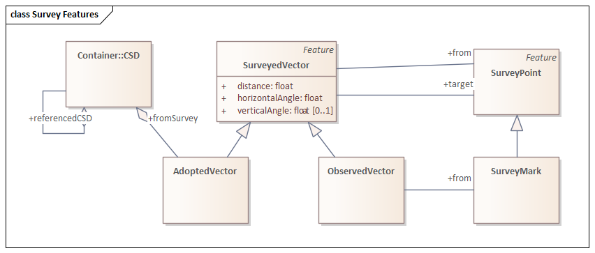
10.8. Conformance Class: Survey Observations
10.8.2. Class: Occupation Observation
An observation to an occupation mark. May be directly observed or calculated from occupation description.
Subclass of
-
Survey Vector Observation (From Survey Observations )
Properties
| Property | Description | Cardinality | Range | Use Case Requirement |
|---|---|---|---|---|
|
from Observation |
has feature of interest |
[1] |
||
|
from Observation |
has result |
[1..*] |
||
|
from Observation |
made by sensor |
[1] |
||
|
from Observation |
observed property |
[1] |
||
|
from Observation |
phenomenon time |
[1] |
||
|
from Observation |
result time |
[1] |
||
|
from Observation |
used procedure |
[0..*] |
||
|
from Observation |
was originated by |
[1] |

Canonical Examples
|
|
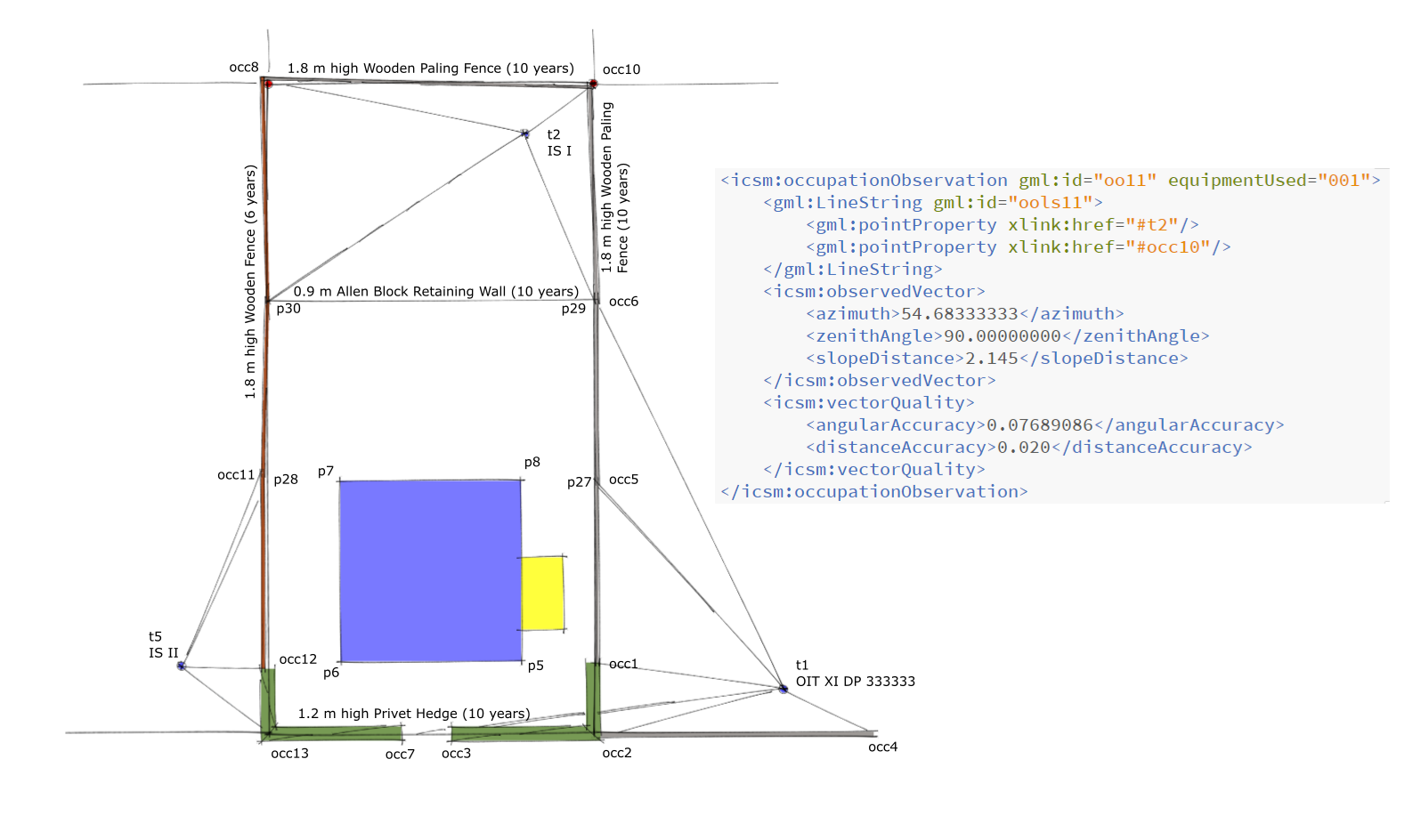
|
10.8.3. Class: Survey Observation
Abstract superclass of observations undertaken during survey activities.
10.8.4. Class: Survey Vector Observation
'An observation of horizontal direction, vertical/zenith angle and direct distance between two survey points or two identifiable points in occupation features.'
|
Note
|
was: An observation of bearings and distance between survey points or identifiable points in occupation features. |
Subclass of
-
Survey Observation (From Survey Observations )
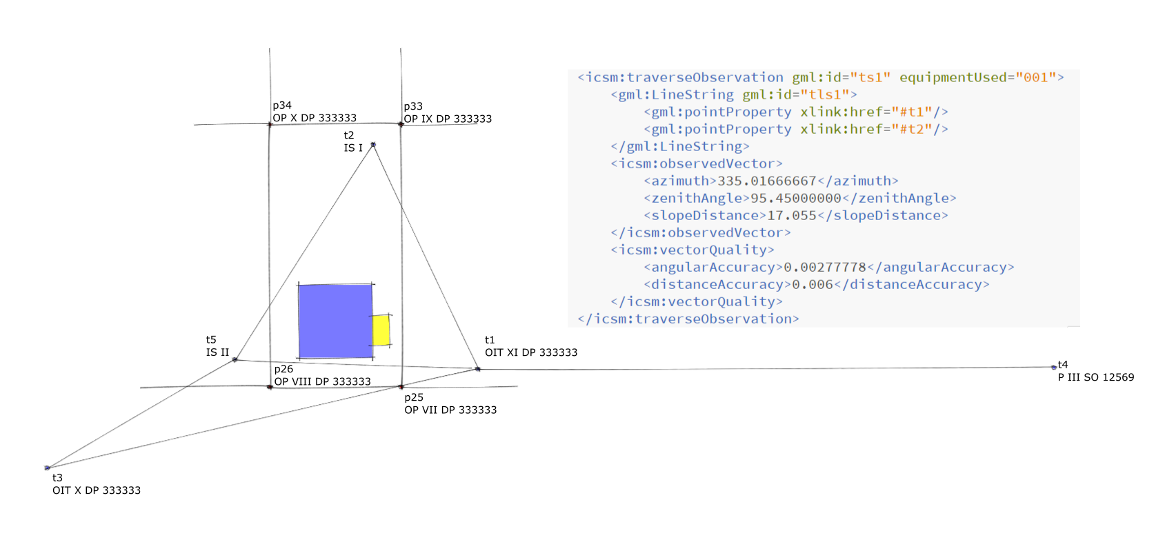
Canonical Examples
|
Description |
Inherits quality measures from containing CSD defaults; |

|
|
|
Description |
Example computed vector - observed using a computational process that is described via procedure where sensor is the implementing software (typically default) |
|
|
|
10.8.5. Class: Traverse
A Traverse comprises a connected set of geodetic and/or cadastral observations. There may be one of more traverses for any one survey. A traverse must include a linear connection path between and identified start and end without loops or multiple paths. A closed traverse has known start and end points.
|
Note
|
Optional - NZ uses the pool of all observations. What is the need to collate a subset as a traverse - what properties does it have? Traverse along a natural boundary, centreline traverse.. all a network with some connectivity. |
10.8.6. Class: Vertex in occupation feature.
A point object with a reference to vertex in some form of model of an occupation feature. This may be a design model or GIS system object.
Subclass of
-
Occupation Mark (From Survey Features )
Annex A: Use Cases
Details
Use Case 3
Use Case 03 - Survey Observations
|
Goal |
Upload all observations (cadastral and occupation) for a cadastral survey dataset (reduced values) to a jurisdictional spatial cadastre that have been used to redefine existing 3D boundaries of a parcel and to define new 3D boundaries that subdivide an existing parcel. |
Preconditions
-
Report Adopted Bearing Rotations
A CSD MAY declare adopted bearing rotations used to orient existing CSD with the current CSD. If no rotation value is specified, it is assumed existing CSD vectors included in the current CSD are oriented in terms of the same datum as the current CSD.
References: NZ Cadastral Survey Rules 2021
§ Vector information
A record of survey must include—
- the source CSD number for each vector, distance, bearing, and arc that has been adopted; and
- any bearing adjustments applied to each CSD from which a bearing is adopted; and
- information indicating whether any bearing, distance, or arc has been calculated, measured, or adopted; and
- for measured vectors, the type of equipment used.
Compare: SR 2010/492 r 9.3
NZ Cadastral Survey Rules 2021
§ Information to be included in survey report
A survey report must contain the following information:
General information
- the purpose for which the survey was conducted, including reference to the statutory provisions relevant to achieving that purpose where it is not otherwise clear:
- an explanation of why a CSD for a Crown subdivision does not include a certificate under section 223 of the Resource Management Act 1991:
Bearings and levels
- the basis for determining the orientation of bearings:
- the basis for any bearing adjustment applied to an adopted bearing:
- the basis for determining the origin of levels:
2021/95 Cadastral Survey Rules 2021 Part 7 r 73
Definition information
- details of any conflict and how it was resolved:
- reasons for not relying on an old survey mark:
- information about old survey marks searched for and not found, or destroyed, if the information cannot be recorded in the record of survey in accordance with rule 80(7):
- reasons for, and details of, decisions made about an existing boundary defined by survey, and the information considered in reaching those decisions:
- if a movable marginal strip is included in a CSD, a description of the method used to determine its existence:
- information about the accuracy of the determination of any water boun‐ dary, water centre-line boundary, or irregular boundary, and the factors taken into account, as specified in rule 29(2):
- any information as to why the physical margin of the water body is no longer coincident with an adopted water boundary for the purpose of rule 10:
Boundary marking
- reasons why it was impracticable to mark any boundary point in terms of rule 35:
- details to support an exemption from marking a boundary point under the provisions in rule 35(1)(a) to (e):
Equipment
- a description of the type of equipment and methods used to ensure com‐ pliance with the accuracy standards in these rules:
Correspondence
- reference to any prior correspondence with LINZ about issues relevant to the application of these rules to the CSD:
- notification from the Māori Land Court of a non-standard appellation used under rule 44:
- notification from the Māori Land Court to support a boundary marking exemption under rule 35(1)(b).
Compare: SR 2010/492 r 8.2
NZ Cadastral Survey Rules 2021
§ Survey report
The survey report must state—
- the basis for determining the orientation of bearings; and
- the basis for any bearing adjustment applied to an adopted bearing; and
- reasons for, and details of, decisions made about an existing boundary point defined by survey, and the information considered in reaching those decisions.
VIC Victorian Cadastral Surveys Practice Directives 2021
§ 6.3.2 If non-conventional measurement techniques have been employed
Due to advancements in technology (e.g. GNSS, laser scanning & photogrammetry), an increasing number of situations will occur where traditional chainage/offset, radiation and traversing methods are not used to complete a cadastral survey. When non-conventional measurement techniques are used, the format of the ‘alternative’ abstract is to be adopted.
An example of an ‘alternative’ abstract of field records is available at:
www.land.vic.gov.au>Surveying>Cadastral Survey>Practice Directives>Abstract of field records alternative
The ‘alternative’ abstract is to clearly show or state:
- the measurement technology used to complete the survey
- the survey datum and survey(s) of origin
- where GNSS was used, the bearings rotated onto MGA bearing datum
- ground or site distances at mean elevation. Spheroid or grid distances are not to be shown on cadastral plans or abstracts of field records
- the measurements that have been derived by means other than direct measurement (i.e. distinguish between derived and direct measurements)
- features (other than traverses) as described in the Surveying (Cadastral Surveys) Regulations 2015 and these practice directives
- any conventional traversing performed shown in the usual manner.
VIC Victorian Cadastral Surveys Practice Directives 2021
§ 2.2.2 ‘Small’ land subdivisions creating fewer than 10 lots, building subdivisions, application surveys under the Transfer of Land Act 1958, boundary plan surveys and Crown surveys
- When there are two or more SCN marks within the parameters of Regulation 13, Survey Co-ordination Regulations 2014, surveyors must do all the following:
- connect to at least two of those SCN marks that are at least 200m apart (or if using GNSS observations, see section 2.3 below)
- connect to at least one other PM or PCM to satisfy Regulation 11(3)(a), Surveying (Cadastral Surveys) Regulations 2015
- rotate the survey onto MGA bearing datum.
- If only one SCN mark exists within the parameters of Regulation 13, Survey Co-ordination Regulations 2014, surveyors must do all the following:
- connect to that SCN mark (or if using GNSS observations, see section 2.3 below)
- connect to at least two other PMs or PCMs to satisfy Regulation 11(3)(a), Surveying (Cadastral Surveys) Regulations 2015
- adopt a bearing datum in accordance with title or a previous cadastral survey or plan.
- If no SCN marks exist within the parameters of Regulation 13, Survey Co-ordination Regulations 2014, surveyors must do both of the following:
- connect to PMs or PCMs to satisfy Regulation 11(3)(a), Surveying (Cadastral Surveys) Regulations 2015
- adopt a bearing datum in accordance with title or a previous cadastral survey or plan.
- When the same surveyor or survey firm has completed a nearby survey within the last five years that is already connected to two SCN marks, the earlier survey can be used for MGA bearing datum without the need to re-connect to those SCN marks. In this case surveyors must do all the following:
- connect to at least two PMs or PCMs from the earlier survey that are at least 200 metres apart
- connect to at least one other PM or PCM to satisfy Regulation 11(3)(a), Surveying (Cadastral Surveys) Regulations 2015
- rotate the survey onto MGA bearing datum.
For scenarios a., b., c. and d. above, surveyors are encouraged to connect to non-SCN marks and unregistered PMs, where they exist within the immediate vicinity of the survey. Refer to section 2.5.1 regarding unregistered PMs.
VIC Victorian Cadastral Surveys Practice Directives 2021
§ 2.2.1 ‘Large’ land subdivision creating 10 lots or more
If a ‘large’ land subdivision creates 10 lots or more at ground level, surveyors must do all the following:
- connect to at least two SCN marks (or if using GNSS observations, see section 2.3 below)
- connect to other PMs or PCMs to satisfy Regulation 11(3), Surveying (Cadastral Surveys) Regulations 2015
- rotate the survey onto MGA bearing datum.
If no suitable SCN marks are located in the vicinity of the subdivision that satisfy the parameters of Regulation 13 of the Survey Co-ordination Regulations 2014, then SCN marks will be established by SGV upon application to the Manager, SGV Geodesy by email to smes.support@delwp.vic.gov.au. Following establishment of the SCN marks, steps a., b. and c. above must be completed.
VIC Victorian Cadastral Surveys Practice Directives 2021
§ 2.2 Specific requirements for connection to the Survey Control Network
On 11 October 2017, the Geocentric Datum of Australia 2020 (GDA2020) was gazetted as the Recognised Value-Standard of Measurement of Position for Australia. MGA2020 is the associated Universal Transverse Mercator (UTM) projection for GDA2020. This replaced the Geocentric Datum of Australia 1994 (GDA94) and associated Map Grid of Australia 1994 (MGA94) as the national datum.
On 1 November 2018, authorised amendments to the Survey Co-ordination Regulations 2014 came into effect and MGA2020 became the official horizontal datum for cadastral surveys in Victoria. GNSS positioning services and SMES were updated to provide MGA2020 coordinate information to support surveying in Victoria. The MGA2020 coordinates for SCN marks have been derived from a rigorous national least-squares adjustment and provide a more accurate position for survey marks compared to MGA94.
In the remainder of the practice directives, ‘MGA’ is to be taken as referring to MGA2020.
The SCN is the network of survey marks in Victoria whose coordinates have been computed by SGV Geodesy through a rigorous least-squares adjustment of observational data. A survey mark that forms part of this network is known as an ‘SCN Mark’ and can be a permanent mark (PM) or primary cadastral mark (PCM) that has adjusted horizontal MGA coordinates. Only SCN marks with adjusted MGA coordinates are to be used when there is a requirement for a cadastral survey to be brought onto MGA bearing datum.
Regulation 11 of the Surveying (Cadastral Surveys) Regulations 2015 requires a licensed surveyor making a cadastral survey to adopt and verify a datum in accordance with a previous cadastral survey or plan. The regulation also stipulates that if an abstract of field records is to be lodged with the Surveyor-General or the Registrar of Titles, the licensed surveyor must “bring the bearing datum onto the Map Grid of Australia 2020 (MGA2020) as is reasonable in the circumstances” – Regulation 11(1)(b).
Bringing the bearing datum of a survey onto MGA means rotating the survey onto the datum and showing the bearings on the plan and abstract of field records relative to MGA2020 Zone 54 or 55.
Regulation 10 of the Survey Co-ordination Regulations 2014 specifies the appropriate MGA zone to be used for cadastral surveys. The zone boundary has been established such that Parishes lie wholly within either zone 54 or 55. Figure 7.3, Part 2, Survey Practice Handbook – Victoria , which is available at www.surveyorsboard.vic.gov.au, shows the location of the zone boundary and the Parishes in its vicinity.
All cadastral surveys commenced after 1 January 2019 for which Regulation 11(1)(b) is applicable must connect to MGA2020 where it can be practically achieved. Connection to MGA2020 for all cadastral surveys except those supporting partial survey subdivisions and Records of having re-established a cadastral boundary will be mandatory from 1 July 2022. Having cadastral surveys connected to MGA2020 is essential for the maintenance and accuracy of the digital cadastre and the lodgement of digital survey files in Single CAD Format File (SCFF), ePlan or other approved formats.
Surveys commenced prior to 1 January 2019, including staged Plans of Subdivision, can remain on their initial bearing datum.
If conventional traversing techniques are employed, then what is “reasonable in the circumstances” is generally governed by the parameters of Regulation 13 of the Survey Co-ordination Regulations 2014. The regulation requires connection to at least two coordinated survey or permanent marks (SCN marks) that fulfil all the following requirements:
- properly verified as to position at the time of survey
- at least 200 metres apart
- within 500 metres of, or a greater distance from the limits of the cadastral survey, if the connection can be made by establishing no more than three instrument points from each SCN mark.
Regulation 7(1)(c) of the Surveying (Cadastral Surveys) Regulations 2015 states that licensed surveyors must ensure all lengths are measured or determined to an accuracy of 10 millimetres + 60 parts per million (PPM). Furthermore, the Surveyor-General’s requirement for the accuracy of an MGA bearing datum determination is at least 20” of arc.
The following discussion elaborates on how surveyors can meet the above requirements as they relate to cadastral surveying. Section 2.3 provides information regarding the conditions for connection to MGA when GNSS observations are used.
VIC Victorian Cadastral Surveys Practice Directives 2021
§ Non-survey guidelines for plans lodged under Section 32, Subdivision Act 1988
An ‘addendum’ abstract of field records and licensed surveyor’s report will normally be required to support Section 32 plans, especially when a new survey was required to compute or mark new boundaries at ground level.
However, plans may be accepted without an abstract of field records if:
- the original survey was carried out by the same surveyor or survey company within the last five years, and no additional land has been included in the plan, and
- the new boundaries can be derived from existing information on the plan or abstract of field records without the need for further survey, or
- the new boundaries are defined by, attached to, or contained within original buildings, and are not required to be marked at ground level.
In cases where it is doubtful if a plan will be accepted without an abstract of field records, surveyors should contact LUV for advice. It is possible that an ‘addendum’ licensed surveyor’s report could be required, which on its own may adequately satisfy the requirements of LUV.
Where an ‘addendum’ abstract of field records and licensed surveyor’s report are supplied, they should:
- satisfy the Surveying (Cadastral Surveys) Regulations 2015
- re-establish the datum of the original survey – partial surveys may be accepted, and
- retain the bearing datum of the original plan/folio if that datum is not MGA, i.e. the original plan/folio was not based on a survey that included a connection to marks with MGA coordinates.
If a connection to MGA is observed in the new survey, an appropriate notation should be shown on the addendum abstract of field records describing the relationship to MGA datum.
QLD Cadastral Survey Requirements v8
§ Meridian
Standard under the SMI Act
See section 3.28 Permanent survey marks – connecting to datum, page 50. See section 9.17 Datum, page 134. See section 9.32 Meridian, page 141.
Where a survey is connected to the State control survey6, MGA bearings must be used to an accuracy of twenty seconds of arc, by derivation from points in the State control survey (such as permanent survey marks with datum lineage coordinates or coordinated CORS) or from astronomical observations.
In all cases where the meridian is shown as MGA the relevant MGA zone must be shown.
Where a survey is not connected to the State control survey, MGA meridian is still preferred, but the survey may be on one of the following meridians:
- County Arbitrary Meridian
- the meridian of the original survey
- the meridian of an adjoining survey.
Where a survey is not required to be connected to datum, but connects anyway in order to obtain MGA meridian, the survey must meet the full requirements of section 3.28 Permanent survey marks – connecting to datum. It should be noted that all surveys using GNSS (whether to obtain MGA meridian or to survey boundaries), must be connected to datum for traceability of position, and therefore must be on MGA meridian.
When using terrestrial observations (e.g. total station) to connect to coordinated marks in order to obtain MGA meridian, permanent survey marks with derived lineage coordinates can be used, but care should be taken to ensure spacing and positional uncertainties (PU) are suitable for achieving a MGA meridian with an accuracy of twenty seconds of arc. When connecting to permanent survey marks with datum lineage coordinates, the survey is thereby connected to datum, and therefore must meet the full requirements of section 3.28 Permanent survey marks – connecting to datum, including being on MGA meridian.
All survey information on any plan must be on one common meridian. A survey covering many plans must be on the same meridian (see section 9.32 Meridian).
A survey that includes boundaries compiled from other plans must bring those boundaries onto the same meridian. Where differences exist when more than one common boundary exists, the common boundary that provides the better closure must be adopted for the meridian swing.
The origin of the meridian must be noted in the meridian box on the front of the plan, or if insufficient space, in a meridian table on the plan.
Survey records may be supplied to support any determination of meridian, e.g. astronomical observations, GNSS information and adjustments. Information from the Survey Control Register is not required to be repeated in survey records.
It is no longer a requirement to note any line on the plan as ‘datum’. However, if considered necessary, a line on the plan may be noted as datum.
QLD Cadastral Survey Requirements v8
§ Meridian by observation
Plans may be related to MGA by using previous plans, astronomical (sun or star) observations, connection to continuously operating reference stations (CORS), or connections to coordinated permanent survey marks.
The meridian box may be completed by reference to MGA and the observation technique. For example:
MGA Zone 56 vide CORS; MGA Zone 56 vide Sun Obs; MGA Zone 56 vide PSMs
Where the survey is connected to datum and the meridian differs from the existing MGA meridian of the underlying plan, a meridian table may be necessary, and the meridian box is completed with:
MGA Zone 56 vide meridian table
The meridian table should be in the form of:
MERIDIAN TABLE MERIDIAN TABLE MERIDIAN TABLE Line Plan Bearing MGA Zone 56 Bearing PM43651 to PM43562 145°25′25″ 145°25′25″ vide SCDB 145°25′25″
Where permanent survey marks are used to obtain meridian, for the presentation of the PSMs refer also to the connections to permanent survey marks as presented in diagrams A and B at the end of section 9.15 Corner information, and if required, the MGA coordinates table as shown in section 3.14.3 Coordinates of cadastral corners.
QLD Cadastral Survey Requirements v8
§ Meridian from previous plan
Where the meridian is referenced to a previous plan, and no reference to MGA, AMG or CAM is known, then the plan number only is required in the meridian box.
Where a previous or adjoining plan has a reference to MGA or AMG or CAM, the meridian box should be completed as follows:
MGA Zone 55 BN582 CAM CAM – add 7°15′ for vide WD4829 – add 5°48′ for vide SL1234 MGA Zone 56 MGA Zone 55 vide SP123456 vide RP801576 MGA Zone 55
Detail is generally shown in the meridian box; however, where space is limited, the meridian information should be shown directly above the title block. For example:
Meridian: Add 6°11′ for MGA Zone 56 vide Plan W31639
QLD Cadastral Survey Requirements v8
§ Meridian from State control survey
Guideline under Standard 3.24 Meridian
Where a survey is connected to datum (i.e. it is connected to the State control survey6 in accordance with section 3.28.1 Connection to datum) and coordinates are determined for marks within the survey in accordance with section 3.14 Coordinates, the accuracy of the derived MGA bearings are dependent on the distance between those marks. If those coordinates had horizontal positional uncertainties at the upper limits allowed in section 3.28.1 Connection to datum, the marks would need to be in the order of 500m apart to provide MGA bearings to an accuracy of twenty seconds of arc.
There will be surveys that are connected to datum that will not extend 500m, in which case a surveyor would need to consider two options to achieve MGA bearings to an accuracy of twenty seconds of arc:
- achieve a lower positional uncertainty on the marks; or
- establish marks some distance from the survey.
However, it is sufficient to satisfy the survey integration intent of 3.28.1 Connection to datum, and section 3.24 Meridian, by establishing coordinated marks with positional uncertainties that satisfy section 3.28.1 Connection to datum, at the extremities of the normal survey (not artificially extended). The MGA bearings derived from those coordinates may then be used, even if that does not provide an accuracy of twenty seconds of arc.
WA Licensed Surveyors (General Surveying Practice) Regulations 1961
§ 27. Azimuth
(1) The direction of a survey line with reference to the meridian must be determined —
(a) by observation; or
(b) by applying the correction for convergence from the nearest point of observation for azimuth.
(2) An azimuth may be adopted from an adjoining survey unless there appears to be a reason to doubt its accuracy.
(3) The derivation of azimuth must be obtained at intervals of not more than 8 km.
[Regulation 27 inserted: Gazette 26 Jul 2013 p. 3466.]
VIC Surveying (Cadastral Surveys) 2015
§ A licensed surveyor making a cadastral survey must—
- adopt and verify a datum in accordance with a previous cadastral survey or plan; and
- if an abstract of field records is to be lodged with the Surveyor-General or the Registrar of Titles, bring the bearing datum on to the Map Grid of Australia 2020 (MGA2020) as is reasonable in the circumstances; and
- if the position of the subject land is shown by a connection, measure that connection unless the position of the subject land has been satisfactorily determined in previous surveys; and
- connect the cadastral survey to relevant permanent marks, pegs and other survey marks; and
- locate and clearly describe any feature on or near the boundaries of the subject land likely to affect those boundaries; and
Reg. 11(1)(b)
amended by
S.R. No. 189/2018 reg. 6.
- locate and clearly describe any feature within the subject land the description and position of which is necessary for the purpose of the survey; and
- determine the length and bearing of each surveyed boundary of the subject land and independently check the accuracy of each determination.
-
All new boundary marks MUST be defined by survey and MAY be marked by a boundary mark.
If a boundary mark is within a structure that does not have a surface accessible for marking and cannot be physically marked it MUST be related to a boundary line mark OR reference mark.
+
| References: | ||||||
|---|---|---|---|---|---|---|
|
NZ Cadastral Survey Rules 2021 § Boundary points must be referencedThe following points or marks on a cadastral survey must be referenced by a permanent reference mark:
Compare: SR 2010/492 r 7.3.1 |
||||||
|
NZ Cadastral Survey Rules 2021 § Boundaries must be marked
Part 4 r 36 Cadastral Survey Rules 2021 2021/95
Compare: SR 2010/492 r 7.1 |
||||||
|
NZ Cadastral Survey Rules 2021 § Boundaries and boundary points to be defined by surveyThe following boundaries and boundary points must be defined by survey:
Compare: SR 2010/492 r 6.2 2021/95 Cadastral Survey Rules 2021 Part 3 r 15 |
||||||
|
NZ Cadastral Survey Rules 2021 § Reference marks where non-primary parcel markedA new or an old mark on a class A or class B boundary point on a non-primary parcel must be referenced in accordance with rule 32. |
||||||
|
NZ Cadastral Survey Rules 2021 § Referencing height-limited boundary points
Compare: SR 2010/492 r 19.1(c) |
||||||
|
SA Notice of the Surveyor-General (No7) - Exemptions § Final Marking of Land Divisions of More Than Five AllotmentsIn relation to the final marking of land divisions of more than 5 allotments, surveyors are exempt from the requirements of Regulation 22 of the Survey Regulations 2020, as regards reinstating pegs marking:
|
||||||
|
WA APX Guide - merged using adobe § Marking GuidelinesThe information provided in this guide is not intended to amount to legal advice. Professional assistance may be required to determine the most appropriate action to protect your legal rights. Please read our Terms of Use on the Land Titles Registration policy and procedure guides web page. Landgate accepts no responsibility where parties print this guide and seek to rely on information that is out of date. Copied from SPPM Chapter 4 |
||||||
|
WA APX Guide - merged using adobe § MarkingThree dimensional boundary corners should be marked directly if practicable. Otherwise a mark should be placed on a vertical edge of the parcel (or its production), on a horizontal or sloping edge or least satisfactorily as an offset mark related three dimensionally to the corner of the lot. In the case of indirect marking it may be preferable to only record the mark in the field book (ie as an RM). It is accepted that it will not be possible to mark or reference those three dimensional corners of the lot which are either high in air space or deep within construction material or earth. In those cases an alternative should be found, for example connections to the structure. |
||||||
|
WA APX Guide - merged using adobe § Timing of MarkingAll of the pegs or posts and most of the reference marks (including Permanent Survey Marks and Permanent Control Marks in Special Survey Areas) of each subdivision should be placed or remain in place after substantial completion of the servicing of the subdivision (generally after roads have been kerbed and sealed, sewers and drainage installed and the verge surfaces smoothed). On normal subdivisions the surveyor should check that all the corners are marked before the plan is lodged and that sufficient referencing remains for accurate re-establishment after the site works have been completed. The initial survey should be planned such that at least three solid control points/reference marks will survive the site works to enable re-pegging and additional referencing when safe from further disturbance. |
||||||
|
WA APX Guide - merged using adobe § SurveyIf the corners are not closely marked in three dimensions, then in the case of urban areas (and especially inner urban and city areas where complex three dimensional surveys are becoming frequent) the survey method and the accuracy of the survey should be at least equivalent to those specified for Special Survey Areas under General Regulation 26A, with nearby connections to the geodetic network in three dimensions. It is recognised that the development methods and the boundary relationship to physical structures will vary greatly between different developments. But the density of marks and of connections to physical structures must correlate with the critical nature of the boundaries and correlate with the high value of the land. It is not acceptable to simply reduce the marking because it is physically impossible to mark most of the corners. Alternatives must be used (possibly unique to each case). landgate.wa.gov.au Page 1 of 5 The sources of the AHD datum for the survey should be recorded in the field book. |
||||||
|
SA Survey Regulations 2020 § 12—Placing or accepting survey marks
|
||||||
|
SA Survey Regulations 2020 § 22—Reinstatement of marks after land division complete
|
||||||
|
SA Survey Regulations 2020 § 11—Survey evidence
|
||||||
|
SA Survey Regulations 2020 § 10—InterpretationIn this Part— allotment has the same meaning as in Part 19AB of the Real Property Act 1886 and in addition includes a community lot, development lot and common property within the meaning of the Community Titles Act 1996 and a unit and common property within the meaning of the Strata Titles Act 1988; coordinated cadastre—see Part 5 Division 1 of the Act; division of land has the same meaning as in Part 19AB of the Real Property Act 1886; Geocentric Datum of Australia 2020 or GDA2020 has the same meaning as in the National Measurement (Recognized-Value Standard of Measurement of Position) Determination 2017 made under section 8A of the National Measurement Act 1960 of the Commonwealth; improvement means a permanent improvement (including a building, fence or wall) situated on or near the boundary of land; Map Grid of Australia 2020 means the system of rectangular coordinates derived from a Universal Transverse Mercator projection of latitudes and longitudes based on the Geocentric Datum of Australia 2020; reference mark means—
revoked regulations means the Survey Regulations 2007 as in force immediately before the commencement of these regulations; survey mark means—
Note— Permanent survey marks are included in the definition of survey mark in section 4 of the Act. survey peg means—
300 millimetres in length and 50 millimetres square at the top and coloured white; or
|
||||||
|
SA Notice of the Surveyor-General (No2) - Marks approved as survey pegs § Application of this NoticeFurther to Regulation 10 of the Regulations, the definition of a survey peg in 10(h), in addition to the items detailed in 10(a)-(g) of the Regulations, a galvanised iron nail driven into a fence post in a rural area and painted white is APPROVED by the Surveyor-General as a survey peg. |
||||||
|
WA Transfer Of Land (Surveys) Regulations 1995 § 2. DefinitionsIn these regulations unless the contrary intention appears — authorised survey has the meaning that it has in the Licensed Surveyors Act 1909; covenant means — (a) a restrictive covenant registered under the Act that is capable of being shown spatially on a plan; or (b) a covenant referred to in section 15 of the Land Administration Act 1997 that is capable of being shown spatially on a plan; Inspector of Plans and Surveys means a surveyor on the staff of the Authority appointed by the Governor to approve plans of authorised surveys; interest means — (a) an easement, memorial or notification that is capable of being shown spatially on a plan; or (b) a covenant; monument means a building, permanent structure or permanent survey mark; plan means a plan to be presented for lodgment with the Registrar; surveyor means a surveyor who is licensed under the Licensed Surveyors Act 1909 and who holds a practising certificate under that Act; terminals means the ends or extents of an easement. [Regulation 2 inserted: Gazette 16 Feb 2001 p. 909; amended: Gazette 29 Dec 2006 p. 5916.] |
||||||
|
SA Notice of the Surveyor-General (No3) - Placing or Accepting Survey Marks § Marking of BoundariesWhile it is necessary to mark each new boundary defined on a cadastral survey, including plans under the Community Titles Act 1996, with a survey peg or offset reference mark it is not necessary to mark existing boundaries redefined by the survey. New boundaries need not be pegged if their improvements are within one metre of the boundary, and the relationship between the boundary and the improvement is shown on the plan. Each new boundary shall be marked with a survey peg as detailed in Regulation 10 (a) of the survey peg definition in the Regulations; a peg of a durable nature, composed of wood, metal or other material approved for the purpose by the Surveyor-General, measuring at least 300 millimetres in length and 50 millimetres square at the top and coloured white. Where the actual boundary position can be pegged but it is not practicable to mark it with a peg as detailed above, a type of survey peg as specified in Regulation 10(b)-(g) of the survey peg definition in the Regulations or, in a rural area, a mark that has been approved as a survey peg by the Surveyor- General in accordance with Regulation 10(h) of the Regulations and notified in the Gazette may be used - see Notice of the Surveyor-General (No 2)—Marks Approved as Survey Pegs, Survey Regulations 2020 for details. Where it is not practicable to mark the actual boundary corner with any type of survey peg as specified in Regulation 10 of the Regulations due to fencing, walls or permanent covering of the boundary, a position offset to the boundary corner is to be marked using a reference mark of a type as specified in Regulation 10 of the Regulations. Where a reference mark is placed offset to the boundary, the relationship between the boundary and the reference mark must, to anyone with an interest in the land, be readily and unambiguously discernible on the ground and on the surveyor’s pegging plan. There is no requirement to show the reference mark location on a plan lodged in the Lands Titles Registration Office. Where a survey peg marking a boundary is not visible from an adjacent peg, survey pegs shall be placed along the new boundary so that from any survey peg on the boundary the adjacent survey pegs are visible. 1.4.1 Divisions of Land into More Than Five Allotments For a division of land into more than 5 allotments, the Surveyor-General DIRECTS, in accordance with Regulation 12 of the Regulations, that the allotment numbers must be placed, in a permanent and durable manner, on the top or face of each survey peg of the types specified in Regulation 10 of the Regulations. In addition, in accordance with Regulation 22(1)(a) of the Regulations, the Surveyor-General REQUIRES the reinstatement of survey pegs within 30 days of the completion of works for the provision of roads, drains or other services in association with the division of land. Refer to Section 14.5 of the Cadastral Survey Guidelines for further details. In accordance with Regulation 22(1)(a) of the Regulations, where the works for the provision of roads, drains or other services in association with the division of land into more than 5 allotments is incomplete, and survey pegs have not been reinstated, the Surveyor-General REQUIRES that the surveyor who has carried out the survey must place the survey pegs required under Regulation 22 of the Regulations within two years of the plan’s deposit by the Registrar-General. |
||||||
|
WA Standard Survey Marks Act 1924 - [03-a0-03] § 4. Powers to enable standard surveys and erecting survey marksAn authorised land officer, or any surveyor specially authorised by him, — (a) may enter and reenter from time to time upon any land, or any public or private road, street or way, with such assistants as he thinks fit, for the purpose of making a standard survey; and (b) may take materials from, or dig and bore into any land, road, street or way, so as to ascertain the nature of the soil, and may mark building, wall, or fence for the purpose of making a standard survey; and (c) may fix or set up thereon or therein any standard survey mark which he considers advisable; and (d) may do all things necessary for carrying out such survey in accordance with any regulations in force for the time being, or for any inspection, renewal, repair, or alteration of any standard survey mark. [Section 4 amended: No. 126 of 1987 s. 48.] |
||||||
|
WA Standard Survey Marks Act 1924 - [03-a0-03] § 2. Terms usedIn this Act — authorised land officer has the meaning given by the Land Administration Act 1997. survey mark means any cairn, beacon, structure, post, peg, block, plug, tube, pipe, spike, pole, or other mark of whatsoever material composed, placed, sunk, or set up as a standard survey mark by the authority of the Surveyor General or, after the commencement of section 46 of the Acts Amendment (Land Administration) Act 1987 1, of an authorised land officer under the powers contained in this Act. surveyor means a surveyor licensed under the Licensed Surveyors Act 1909. [Section 2 amended: No. 126 of 1987 s. 46; No. 14 of 1996 s. 4; No. 31 of 1997 s. 141.] |
||||||
|
SA Notice of the Surveyor-General (No1) - Accuracy § Marks and ImprovementsThe difference in the horizontal position of survey marks, reference marks and improvements placed or connected on the survey, and the position of those survey marks and improvements as determined from measurements shown on the plan must not exceed in:
Where survey marks, reference marks or improvements are adjacent to a boundary between different accuracy zones the tolerance of the higher accuracy zone shall apply. |
||||||
|
VIC Victorian Cadastral Surveys Practice Directives 2021 § Indirect markingWhere direct marking of title corners is impractical or inappropriate, another form of marking the boundaries in the vicinity of the corners, such as offset marks, is to be implemented. This may include, but is not limited to, situations where access to an adjoining property is not possible (e.g. fencing surrounding the land under survey is too high) or, when the placement of a boundary mark at a corner would result in it being inaccessible and not capable of being used for construction on the subject land. Where indirect marking of title corners is implemented, the boundary marks placed are to relate closely to the boundaries at regular distances. Offset marks are to be placed at regular offsets (e.g. 1m x 1m) or, where appropriate and practicable to do so, on the production of boundaries at a regular distance (e.g. 1m, 1.5m, 2m…). Title pegs are not to be used as offset or production marks for indirect marking of corners. |
||||||
|
VIC Victorian Cadastral Surveys Practice Directives 2021 § Boundary marking in re-establishment surveysBoundary marking is to be performed in accordance with the requirements of section 3 of these practice directives. Licensed surveyors are to apply their professional judgement to determine if, how and when boundaries are to be marked. All boundary marks placed at the date of the completion of the re-establishment survey are to be shown on the RE Plan. The date of completion is the date on which the site was last visited for the purpose of the re-establishment survey and, in many circumstances, will be the date on which the site was revisited to perform the required boundary marking following the computation of the re-establishment. It is acknowledged that there are many circumstances where the marking of boundaries in re-establishment surveys may be inappropriate, impractical or needs to be delayed. Some of these are listed in section 3. In such situations, the reason why boundary marking did not occur at the date of the completion of the re-establishment survey is to be stated on the RE Plan or accompanying report, if provided. If the circumstances are such that boundary marks are required to be placed many months after the re-establishment survey, the RE Plan must still be lodged within 60 days of the re-establishment survey but there is no requirement to provide the Surveyor-General with details of any boundary marks placed after the registration of the RE Plan. |
||||||
|
VIC Victorian Cadastral Surveys Practice Directives 2021 § Marking of boundariesIn accordance with the requirements of Regulation 9, Surveying (Cadastral Surveys) Regulations 2015, a key objective of a cadastral survey is marking the title boundaries of the parcel(s) defined in the survey. Title boundaries can be marked either directly or indirectly, given the circumstances on the ground, with the preference being for direct marking of boundary corners where practicable. Licensed surveyors are to apply their professional judgement to determine if, how and when boundaries are to be marked. The default position is that boundaries must be marked where it is appropriate and practicable to do so. |
||||||
|
VIC Victorian Cadastral Surveys Practice Directives 2021 § Direct markingWhere direct marking of title boundaries is practicable, boundary marks are to be placed at the perimeter corners of the land under survey. Intermediate boundary ‘line’ marks are also required at distances no greater than 200 metres apart on boundaries of significant length and/or when the ends of the boundaries are not intervisible. It is important that boundaries are marked such that there is no doubt or ambiguity on the ground regarding their identification, location and direction. Options for providing identification of boundaries and their direction include trenching, staking, stamping numbers on pegs (front and rear); or, by using a combination of these methods. In each case, the surveyor must apply their professional judgement about the most appropriate method of defining or indicating the direction of the boundary on the ground. In rural environments, and when appropriate in urban areas, the preferred method of indicating boundary direction is by trenching, rock-filled trenches, or laying rock mounds. Spray paint directional markings are acceptable on hard artificial surfaces such as concrete and bitumen, but are not to be used on natural surfaces. When numbers are stamped on pegs, the numbering must be done in such a manner that the interpretation of the lot numbers cannot be ambiguous. |
||||||
|
VIC Victorian Cadastral Surveys Practice Directives 2021 § 6.1.2 Life of a survey and abstract of field records
|
||||||
|
VIC Victorian Cadastral Surveys Practice Directives 2021 § 6.3.1 If conventional traversing techniques have been employedIf surveys are carried out using conventional traversing techniques, the abstract of field records to be lodged is to take the format of the ‘traditional’ abstract of field records. The abstract is to show all traverse lines, chainages, radiations, offsets, fence and mark descriptions etc. as described in the Surveying (Cadastral Surveys) Regulations 2015 and these practice directives. An example of a ‘traditional’ abstract of field records is available at: www.land.vic.gov.au>Surveying>Cadastral Survey>Practice Directives>Abstract of field records traditional |
||||||
|
SA Notice of the Surveyor-General (No6) - Approved Form of Certificate § That the field work was completed on the …… day of 20……
|
||||||
|
NSW Surveying And Spatial Information Regulation 2017 § Use of reference marks
Section reference - please refer to original document.
In future this may be provided as a link to a published Linked Data
version of the document database.
|
||||||
|
NSW Surveying And Spatial Information Regulation 2017 § Boundary marks
Section reference - please refer to original document.
In future this may be provided as a link to a published Linked Data
version of the document database.
|
||||||
|
NSW Surveying And Spatial Information Regulation 2017 § Surveys for affecting interests
Section reference - please refer to original document.
In future this may be provided as a link to a published Linked Data
version of the document database.
|
||||||
|
NSW Surveying And Spatial Information Regulation 2017 § Surveyor to furnish survey certificate
Section reference - please refer to original document.
In future this may be provided as a link to a published Linked Data
version of the document database.
|
||||||
|
NSW Surveying And Spatial Information Regulation 2017 § Roads to be marked with reference marks
Section reference - please refer to original document.
In future this may be provided as a link to a published Linked Data
version of the document database.
|
||||||
|
NSW Surveying And Spatial Information Regulation 2017 § Marking of rural surveys
Section reference - please refer to original document.
In future this may be provided as a link to a published Linked Data
version of the document database.
|
||||||
|
NSW Surveying And Spatial Information Regulation 2017 § Forms and styles of survey marks
Section reference - please refer to original document.
In future this may be provided as a link to a published Linked Data
version of the document database.
|
||||||
|
NSW Surveying And Spatial Information Regulation 2017 § Conventional signs and symbols to be used on survey plansIn the preparation of any survey plan, the conventional signs and symbols set out in Schedule 5 must be used to indicate the matters to which they are referred by that Schedule. |
||||||
|
NSW Surveying And Spatial Information Regulation 2017 § Surveyor to note nature and position of survey marks etc
Section reference - please refer to original document.
In future this may be provided as a link to a published Linked Data
version of the document database.
|
||||||
|
NSW Surveying And Spatial Information Regulation 2017 § Procedure on finding existing corner peg and reference markIf a corner peg and reference mark are found together, a surveyor must determine the bearing and distance between them and, if a difference from the original reference is disclosed, must decide from other evidence which of them to adopt and note details of the difference on the survey plan. |
||||||
|
NSW Surveying And Spatial Information Regulation 2017 § Method of showing boundaries generally
Section reference - please refer to original document.
In future this may be provided as a link to a published Linked Data
version of the document database.
|
||||||
|
NSW Surveying And Spatial Information Regulation 2017 § First survey of boundary of land adjoining Crown reserve or Crown road
Section reference - please refer to original document.
In future this may be provided as a link to a published Linked Data
version of the document database.
|
||||||
|
NSW Surveying And Spatial Information Regulation 2017 § General principles of surveyWhen carrying out a survey, a surveyor must, in accordance with this Part—
|
||||||
|
NSW Surveying And Spatial Information Regulation 2017 § Marking of urban surveys
Section reference - please refer to original document.
In future this may be provided as a link to a published Linked Data
version of the document database.
|
||||||
|
SA Cadastral Survey Guidelines - V4 - 24 August 2020 - APPROVED § Cadastral Survey GuidelinesPermanent survey marks are included in the definition of survey mark in section 4 of the Act. survey peg means—
The marking provisions of Notice of the Surveyor-General Nos 3 & 4 apply to all cadastral surveys for which plans are lodged in the Lands Titles Registration Office, except for plans for information purposes (PPG 2.24.3 requires at least two PSMs for the latter). Notice of the Surveyor-General (No 4) – Placing Permanent Survey Marks and Provision of Information for Permanent Survey Marks 1.3 and 1.4 restricts where some types of PSMs may be used and that brass plaques shall be used on conventional PSMs placed. It specifies PSM numbers and spacings, protection, and coordination. Notice of the Surveyor-General (No 2) - Marks Approved as Survey Pegs approves survey peg types for different circumstances. |
||||||
|
SA Cadastral Survey Guidelines - V4 - 24 August 2020 - APPROVED § Original PeggingMarks placed as part of the original delineation of a boundary carry considerable weight in subsequent redeterminations of that boundary. … a rule to which I referred in the course of the argument, has been laid down in the American Courts… I have quoted it many times in this Court from the Bar, and I now quote it again from the Bench:- “The object in cases of this kind is to interpret the instrument - that is, to ascertain the intent of the parties. The rule to find the intent is to give most effect to those things about which men are least liable to mistake. On this principle the things usually called for in a grant - that is, the things by which the land granted is described - have been thus marshalled in America:
Donaldson v Hemmant (1901) The following cases involved disputes over original pegging conflicting with measurement:
To hold that a person who enters and takes possession by the survey pegs is not entitled to hold that possession, but only to hold possession of what the Land Transfer certificate calls the section, not what the survey pegs mark it out to be, would be to introduce confusion into all the surveys of the colony.
…the position of the defendant’s land was to be ascertained by the original allotment peg, and that she was entitled to the land in dispute.
It was proved to my satisfaction that subdivision 10 was, at the time of sale, marked by pegs corresponding to the four corners of the land as now occupied by the defendant… …and that the land intended to be comprised in the transfer and certificate of title for subdivision 10 was bounded by that line on the west, and that this is the proper construction of both those instruments.
The land is precipitous, in many parts covered by timber and what is called horizontal scrub…’ In the last case the conclusion was that the terrain did not allow for accurate measurement. In all four cases indications were that measurement, or its starting point, was the thing most likely to have been in error. The fact that a later and more accurate survey discloses errors in the original measurements is immaterial where the evidence of the boundaries is otherwise not in doubt… Hallmann (para 13.13) In the case South Australia v Victoria (1914) later and more accurate surveys also disclosed error in original measurement: …the 141st degree of east longitude proclaimed for the South Australian eastern boundary, was marked on the ground 4.03 kilometres west of its true astronomical position. Nevertheless, it was held by the Privy Council that the correct position of the boundary was that established and marked by the surveyors on the ground and agreed upon by the adjoining States. Hallmann (para 13.17). |
||||||
|
SA Cadastral Survey Guidelines - V4 - 24 August 2020 - APPROVED § Limited Survey ConditionsThe following conditions apply to the use of these limited surveys:
|
||||||
|
SA Cadastral Survey Guidelines - V4 - 24 August 2020 - APPROVED § Cadastral Survey Guidelinesnote 52 on affected CTs. Prior to survey all affected residents are to be advised (by letter drop) by the surveyor of the nature of work being done and the date of commencement. During the course of the survey residents should be consulted, particularly when there are occupation anomalies. It is important for the surveyor to be alert to mutual agreements or of disputes between neighbours. The pegging18 of corners in a CBA defined on a plan lodged in the LTRO may be delayed until after approval for data by the LTRO19. Under s51(4) of the Survey Act 1992 the Council and all persons with a registered interest in the land, in land adjoining the land, and land likely in the opinion of the Surveyor-General to be directly or indirectly affected, are notified by a registered letter that the plan is open for inspection in the Surveyor-General's Office or at the Council, for a period of 28 days. These persons may make objections to the Surveyor-General relating to the determination of land boundaries. Under s51(5a) of the Act the representations are considered by the Surveyor-General, in consultation with the Registrar-General, who informs the person making the representation, and any other persons affected, of the action taken. Subsequent alterations to the plan require re-acceptance of the plan by the LTRO. Following expiration of the objection period the surveyor may be consulted by the Surveyor- General and if necessary required to make alterations to the plan. The role of the Surveyor-General, as an impartial arbiter in the determination of equitable solutions of boundary alignments, is provided in s51(6) of the Act. Under s51(7) of the Act the Surveyor-General then advises the surveyor responsible for the survey and all those required to be notified under s 51(4), allowing for changes in registered interests since notification, of the plan’s terms of approval or modification and reasons for the decision as to those terms. In effect, the Surveyor-General determines the position of the boundary alignments20. These may differ from those determined by the surveyor. Under s51(8) of the Act fourteen days is allowed for objection to the Land and Valuation Division of the Supreme Court with respect to this approved or modified plan. Ultimately it may be the Court that has the final say in the position of boundaries. 18 CBA surveys result in the creation of new boundaries in lieu of old ones. As such, all boundaries whether road, side or rear must be marked in accordance with Notice of the Surveyor-General (No 3). Note, particularly, that it is not necessary to mark corners within one metre of occupation shown on the plan. See also section 14. 19 S51(2)(a) requires that a report is lodged with a plan defining boundaries in a CBA. The report should follow the guidelines set out in section 17 and in addition provide reasons for the positions of the boundaries. 20 An objection from any person with a registered interest is therefore lodged against the boundary alignments determined by the Surveyor-General. KNet 14708580 24 August 2020 Page 62 of 161 Cadastral Survey Guidelines |
||||||
|
SA Cadastral Survey Guidelines - V4 - 24 August 2020 - APPROVED § Cadastral Survey Guidelinesafter completion of the survey and complies with any applicable directions given by the Surveyor- General.
While the marking of existing boundaries is optional, regulation 12 (1) requires all new boundaries to be pegged. The actual corner must be directly marked with a survey peg unless:
In these cases Notice of the Surveyor-General’s (No 3) – Placing or Accepting Survey Marks 1.4 allows for reference marks to be placed offset to the corner (refer to section 14.4a2 for approved mark types). While these offset reference marks are not required to be shown on a plan of cadastral survey lodged in the Lands Titles Registration Office, regulation 12 (1) of the Survey Regulations 2020 places an obligation on surveyors to ensure the boundary is readily and unambiguously discernible on the ground; if impracticable to mark corners with survey pegs surveyors must be able to demonstrate suitable communication of the type and spatial relationship of the marking of the new corner to any person with an interest in it. Placement of reference marks offset to new corners is not an acceptable reason, on its own, for failing to directly peg the actual new corner. If a survey peg can be driven at the new corner on the subject land side of an existing fence then it must be done so. Proposed site demolition, or the inconvenience of returning to a rural site after calculating a redefinition, do not excuse failure to peg new boundaries at plan certification. Surveyors, however, may apply for exemption to delay pegging of particular boundaries (see section 1.3); exemption requests should include a proposed date by which pegging will be completed. Notice of the Surveyor-General’s (No 3) – Placing or Accepting Survey Marks 1.4 provides exemption from new boundaries being pegged if occupation is within one metre of the new boundary, and the relationship between the occupation and the new boundary is shown on the plan. The above exemption does not apply if the new boundary is unoccupied. Suitable notation should be shown on the plan if it is not possible to mark new corners, for example, if under water at the time of survey. Notice of the Surveyor-General’s (No 3) – Placing or Accepting Survey Marks 1.4 requires that where adjacent corners on unoccupied new boundaries are not intervisible, datum pegs must be placed at appropriate positions along the line to allow intervisibility between adjacent pegs. Where the boundaries are to be fenced, the placement of datum pegs at intervals not exceeding 250 metres is recommended. It is not necessary to show datum pegs on the plan. Every boundary established on a survey for an application pursuant to Part VIIA of the Real Property Act 1886 shall be marked with a survey peg, unless their improvements are within one metre of the boundary and the relationship between the boundary and the improvement is shown on the plan. |
||||||
|
SA Cadastral Survey Guidelines - V4 - 24 August 2020 - APPROVED § IntroductionIn determining the marking requirements for a cadastral survey the surveyor must meet the requirements of the survey instructions irrespective of their client’s needs or wishes. Marking of unlodged identification surveys is optional. The aim of these survey instructions is to ensure that the location and extent of peoples’ interest in land is readily identifiable. In the short term this includes land purchasers, not just the surveyor’s client. In the longer term it means that both new and existing boundaries defined in the survey may be later resurveyed as an unambiguous technical exercise. General objectives in meeting this aim are:
The exception from final placement of survey marks in the certification (Notice of the Surveyor- General (No 6) – Approved Form of Certificate) only applies to final marking of divisions into more than five allotments. All other surveys must not selected this exception. As community divisions are a cadastral survey they must fulfil the marking requirements of the survey instructions, consistent with other land division. The following may not provide flexibility surveyors require in unusual circumstances; surveyors are reminded of the procedure for seeking exemption from survey instructions (see section 1.3). |
||||||
|
SA Cadastral Survey Guidelines - V4 - 24 August 2020 - APPROVED § Marking of BoundariesRegulation 12 prescribes the boundary marking requirements for cadastral surveys: 12 - Placing or accepting survey marks
|
||||||
|
QLD Cadastral Survey Requirements v8 § Corner marksSee section 3.23 Marking, page 43. See Part 4 of the Survey and Mapping Infrastructure Regulation 2014. Corner marks refer to the survey marks and/or branded occupation found, placed or adopted at all new or existing corners on the survey (e.g. pegs, survey posts or survey marks in occupation at the corner to represent the corner). For example: OP; Peg pld; Rmns OSP; O Ramset In Br Wall; Screw in Conc fd The type of nail can be shown (e.g. clout, ramset, spring head). |
||||||
|
QLD Cadastral Survey Requirements v8 § Guidelines for marking boundariesGuideline under Standard 3.23.1 Boundary marking Lot numbers should be marked on corner pegs. For rural surveys, where a fence post is used as a corner it should be branded with a broad arrow and the lot number except where a reference tree is taken. For rural surveys, alternate marks such as a survey post, a galvanised iron pipe or star picket may be placed at corners where circumstances so dictate, provided such marks are identifiable as survey marks. New boundaries should be marked sufficiently to enable the boundary to be readily and unambiguously discernible on the ground at the completion of survey. Where clearing is required to undertake the survey, this should be done in a way that minimises the impact on native flora and fauna (e.g. lopping of branches rather than removal of trees). Surveyors should be aware of Vegetation Protection Orders, Voluntary Conservation Management Agreements, cultural heritage legislation (Aboriginal Cultural Heritage Act 2003) and other environmental considerations (e.g. Vegetation Management Act 1999). Further information is given below in relation to clearing of vegetation for survey purposes. Unless fencing is to proceed immediately, subject to environmental considerations, trees standing nearest to the line may be blazed with a horseshoe shaped mark cut into the heart-wood on opposite sides of the tree in such positions that the marks face along the survey line. Trees through which the boundary line passes should be double blazed on opposite sides so that the marks face along the boundary line. Where corner marks are not intervisible, sufficient marks should be placed on line between the corners so that the boundary is readily and unambiguously discernible on the ground. |
||||||
|
QLD Cadastral Survey Requirements v8 § Cadastral survey marksStandard under the SMI Act A cadastral survey mark that identifies a boundary must be a peg capable of resisting destruction, corrosion or decay that is at least 350 millimetres in length, is coloured white and has a square top with a minimum cross-section of 50 millimetres for a sufficient distance from the top to provide for branding. If a surveyor considers that it is impracticable or unsuitable to use a mark of this type, the surveyor may place a survey mark of equivalent durability and stability, and as far as practicable, of a similar character so that they are recognisable as cadastral boundary marks (for example, if pegs are placed, then they must not be oblong or a colour other than white). A cadastral reference mark may be any of:
Factors to consider when marking a boundary are:
|
||||||
|
QLD Cadastral Survey Requirements v8 § Boundary markingInformation Section 9 of the Survey and Mapping Infrastructure Regulation 2014 establishes the following principles for the marking of boundaries on a cadastral survey: ‘3) A boundary of land must be marked on the land in a way that a person on the land can identify the boundary. 4) However, subsection (3) does not apply if— (a) the client of the surveyor marking the boundary gives the surveyor written notice that the client does not require the boundary to be marked as required by subsection (3); and (b) the surveyor complies with the relevant survey standard for the marking; and (c) the reference points used for the survey include a recognised permanent survey mark placed in carrying out a State control survey.’ It should be noted that the reference in section 9(4)(a) to ‘marking the boundary’ is a reference to marks along the boundary between the end points (e.g. line pegs, clearing, blazing of trees). It does not remove the need to mark the end points (i.e. the corners)—see the standard below. Standard under the SMI Act While it is recognised that many boundaries are not physically run, but are determined through traverses, offsets and in some instances through GNSS observations, all boundaries must be surveyed and marked in accordance with the requirements of Part 4 of the Survey and Mapping Infrastructure Regulation 2014. Therefore, the requirement to mark the boundary between the end points is necessary when a person cannot readily identify where the boundary lies between those end points. The length of the boundary and topography between the end points will determine if line pegs, clearing or tree blazing is required to satisfy section 9(3) of the Survey and Mapping Infrastructure Regulation 2014. Regardless of whether intermediatory marking is placed along a boundary or not, the following requirements apply to the marking of cadastral corners (the end points of each boundary):
|
||||||
|
QLD Cadastral Survey Requirements v8 § Guidelines for reference markingGuideline under Standard 3.23.2 Reference marks An efficient cadastral system necessitates that an adequate number of reference marks are placed on all cadastral surveys to enable the future reinstatement of lot boundaries. Reference marks placed by surveyors need to be durable and reliable. The number, position, type and combination of reference marks should be placed in the course of a survey to maximise their longevity into the future. A variety of surface marks (permanent survey marks, nails, screws, drill holes, reference trees, building corners, etc) and subsurface marks (iron pins, etc.) are to be utilised. |
||||||
|
WA Licensed Surveyors (General Surveying Practice) Regulations 1961 § 40. Kilometre posts(1) If the length of any boundary exceeds 2 km, numbered referenced kilometre posts shall be placed on the boundary. (2) Posts and reference marks shall be similar to those placed at angles. [Regulation 40 inserted: Gazette 1 Sep 1972 p. 3412; amended: Gazette 26 Jul 2013 p. 3472.] |
||||||
|
WA Licensed Surveyors (General Surveying Practice) Regulations 1961 § 38. Specifications of reference marks(1) A reference mark shall be an iron spike at least 0.01 m in diameter and 0.4 m long, driven flush into a paved surface or sunk, where practicable, at least 0.25 m below an unpaved surface. (2) Where such marks are not reasonably available or conditions are unsuitable for their use, alternative marks of other materials of equivalent durability and stability may be used. (3) A full description of alternative marks used must be shown in the field record. (4) Marks with a head or lip such as bridge nails or dog spikes should not be placed in situations where they are to be excavated for use. [Regulation 38 inserted: Gazette 9 Nov 1979 p. 3520; amended: Gazette 26 Jul 2013 p. 346970.] |
||||||
|
WA Licensed Surveyors (General Surveying Practice) Regulations 1961 § 47. Marking boundaries of pastoral and timber leases(1) The boundaries of pastoral and timber leases shall be marked in a similar manner to other lands, with the exception that the intermediate marks may be placed at intervals of not more than 500 m. (2) These marks may be flattopped pegs, 0.075 m square, and 0.4 m long, sunk 0.3 m in the ground, with consecutive numbers clearly cut or stamped thereon, or spikes or bottles. (3) Kilometre posts shall be placed as provided in regulation 40, and alternative use of concrete blocks as specified in paragraph (a) of the Table to regulation 36 shall be permitted. [Regulation 47 inserted: Gazette 1 Sep 1972 p. 3413; amended: Gazette 5 Sep 2000 p. 5060; 26 Jul 2013 p. 34734.] |
||||||
|
WA Licensed Surveyors (General Surveying Practice) Regulations 1961 § 39. Intermediate marks(1) On all permanent boundaries that exceed 250 m in length a mark consisting of an iron spike at least 0.01 m in diameter and 0.4 m long driven flush, shall be placed exactly on the alignment at intervals not exceeding 250 m such that from each mark at least one other mark is visible forward and backward. (2) Where such marks are not reasonably available or conditions are unsuitable for their use, alternative marks of other materials of equivalent durability and stability may be used. (3) A full description of alternative marks used must be shown in the field record. [Regulation 39 inserted: Gazette 9 Nov 1979 p. 3520; amended: Gazette 26 Jul 2013 p. 3470.] |
||||||
|
WA Licensed Surveyors (General Surveying Practice) Regulations 1961 § 48. Positioning of marksA mark must clearly indicate the position of the boundary that the mark is intended to indicate. [Regulation 48 inserted: Gazette 26 Jul 2013 p. 3474.] |
||||||
|
WA Licensed Surveyors (General Surveying Practice) Regulations 1961 § 26. New alignments(1) All new boundary lines shall be accurately ranged and measured except where distances and alignments can be computed from connections with another fully ranged line such as the opposite side of a road, an offset, traverse, or similar line parallel or nearly so. (2) Boundaries with calculated distances must be cleared and marked in accordance with these regulations. (3) Where a new survey line intersects an unsurveyed boundary of leasehold land or freehold land, the intersection shall be marked in accordance with these regulations. [Regulation 26 amended: Gazette 4 Aug 1965 p. 2223; 5 Sep 2000 p. 5057; 26 Jul 2013 p. 34656.] |
||||||
|
WA Licensed Surveyors (General Surveying Practice) Regulations 1961 § 36. Specification of survey marks(1A) The corners and angles of a boundary or land parcel must be marked in accordance with this regulation. (1) Posts and pegs are to be made from jarrah, jam (wood) wandoo, steel, concrete or polypropylene. (2) Survey marks are to be placed so that they are firm and stable. (3) The size of posts or pegs is determined by the area enclosed by the perimeter upon which they are placed in accordance with the Table to this regulation. (4) Where pegs or posts are placed on 2 adjoining perimeters of different categories the larger size is to be used on the angles of the common boundary. (5) Where a mark specified in the Table to this regulation is inappropriate, an alternative mark which — (a) is of equivalent durability and stability to the specified mark; and (b) is identifiable as a cadastral mark; and (c) sufficiently resembles a standard mark so as to be identifiable as such by the public, may be used. (6) Where, in accordance with subregulation (5), an alternative mark is used a full description of the mark is to be shown in the field record. (7) Where practicable all exposed portions of posts and pegs — (a) shall be coloured white; or (b) if they are hardwood pegs 75 mm square, may be coloured red. (8) All concrete posts are to be topped by a secure noncorrosive metal plate. (9) The numbers of all relevant land parcels are to be marked on the post or peg on the side or top respectively facing the parcel and in the direction so as to be read from within the parcel with — (a) where the land is rural land, “R” marked towards the road abuttal; or (b) where the land is urban land, “R” marked towards the road abuttal where it would add to clarity. Table
Area over 4 ha: A hardwood post, pointed at the top, 100 mm square, at least 0.6 m long, a concrete post, 60 mm square, at least 0.45 m long, a steel post or peg, 60 mm square, at least 0.9 m long or a mark made from polypropylene, 75 mm square, at least 0.45 m long. Area 4 000 square metres to 4 ha: A peg, 75 mm square, at least 0.35 m long, a concrete post 60 mm square, at least 0.45 m long or a steel peg 75 mm square, at least 0.6 m long. Area under 4 000 square metres: A peg, 50 mm square, at least 0.35 m long or a concrete post, 50 mm square, at least 0.4 m long. [Regulation 36 inserted: Gazette 5 Sep 2000 p. 50589; amended: Gazette 12 Sep 2003 p. 4075; 22 Apr 2005 p. 13423; 26 Jul 2013 p. 3468.] |
||||||
|
WA Licensed Surveyors (General Surveying Practice) Regulations 1961 § 42. Road surveys(1) When marking both sides of a new road, the angle posts on both sides will be referenced according to regulation 37. (2) Where a surveyor is instructed to mark only one side of a road, the surveyor must set out posts for the angle points on the opposite side of the road, according to its width and reference them, as specified above, but without intermediate marks or trenches or line clearing. [Regulation 42 amended: Gazette 26 Jul 2013 p. 34723.] |
||||||
|
WA Licensed Surveyors (General Surveying Practice) Regulations 1961 § 50. Line clearing(1) Subject to environmental considerations, any new boundary line must be cleared sufficiently to indicate the position of the boundary. (2) A boundary line or part of a boundary line that has not been cleared in accordance with subregulation (1) must be shown in the field record as not having been cleared. [Regulation 50 inserted: Gazette 26 Jul 2013 p. 3475.] |
||||||
|
WA Licensed Surveyors (General Surveying Practice) Regulations 1961 § 37. Placement of reference marks(1) This regulation applies in relation to the survey of a boundary. (2) Two reference marks must be placed — (a) if it is the boundary of a land parcel that is greater than 4 ha — at each angle of the boundary; or (b) if it is the boundary of a land parcel that is equal to or less than 4 ha — at key points along the boundary; or (c) if it is another boundary — at each corner and angle of the boundary. (3) Each of those reference marks must be related by distance and, if practicable, direction to an alignment. (4) The distance between those reference marks must be measured, and recorded in the field record, to the nearest millimetre. (5) A single reference mark (without trenching) must be placed at each instrument point that is not otherwise permanently marked. (6) The objective of the placement of a reference mark is to ensure its long term stability and accessibility. [Regulation 37 inserted: Gazette 26 Jul 2013 p. 34689.] |
||||||
|
WA Licensed Surveyors (General Surveying Practice) Regulations 1961 § 41. Shorter boundaries(1) When 2 or more adjoining boundary lines are 100 m or less in length the mark to be placed at the angle between them may be as specified in paragraph (c) of the Table to regulation 36. (2) If, as in the case of traverse of a natural feature or the marking of a winding road or a railway boundary, there are more than 5 consecutive boundaries less than 100 m long, reference spikes may be omitted from every second pair of angles. [Regulation 41 amended: Gazette 1 Sep 1972 p. 3412; 5 Sep 2000 p. 5060; 26 Jul 2013 p. 3472.] |
||||||
|
WA Licensed Surveyors (General Surveying Practice) Regulations 1961 § 23. Remarking connecting boundary between old and new surveys(1) This regulation applies if a surveyor is required under regulation 22 to connect a new survey to an old survey. (2) In this regulation — connecting boundary, in relation to a new survey, means the boundary connecting the new survey to an old survey. (3) The surveyor must range sufficient of the connecting boundary to verify its alignment. (4) For the purposes of subregulation (3), it is sufficient if the surveyor uses — (a) 3 reliable, reasonably spaced marks; or (b) fewer such marks as approved by the Surveyor General. (5) For the purposes of subregulation (3) — (a) all portions of any old survey line must be carefully measured; and (b) if the land being surveyed is rural land and the measurements taken in accordance with paragraph (a) are found to be in disagreement with the measurements previously accepted in relation to the old survey line by an average of more than 1:4000 — the old survey line must be carefully remeasured and the results of the remeasure must be recorded in the field record. (6) The surveyor must, as necessary — (a) replace the posts and pegs used in the old survey to mark the connecting boundary; and (b) clearly indicate the direction of the connecting boundary. [Regulation 23 inserted: Gazette 26 Jul 2013 p. 34623.] |
||||||
|
WA Licensed Surveyors (General Surveying Practice) Regulations 1961 § 40A. Streets, rightsofway, pedestrian access ways, drainage reserves and railways: additional requirements(1) This regulation applies in relation to the survey of a street, rightofway, pedestrian access way, drainage reserve or railway in addition to regulations 37, 38 and 39. (2) Each corner and angle of the street, rightofway, pedestrian access way, drainage reserve or railway must be marked by a peg or post as specified in paragraph (b) of the Table to regulation 36 the exposed portion of which must be coloured red. (3) At any truncated corner of the street, rightofway, pedestrian access way, drainage reserve or railway — (a) the intersection of 2 adjoining alignments must be marked with a single reference mark; and (b) 2 other reference marks, each being related by angle and distance to those alignments, must be placed in positions so as to minimise the chance of disturbance and to enable the reestablishment of both alignments. (4) If a corner or angle of the street, rightofway, pedestrian access way, drainage reserve or railway is not intervisible with an adjoining corner or angle, the intermediate instrument point (being the point from which both corners or angles are visible) must be marked by a single reference mark (without trenching) and the distance to that point from each of those corners or angles must be recorded in the field record. [Regulation 40A inserted: Gazette 26 Jul 2013 p. 3471.] |
||||||
|
VIC Surveying (Cadastral Surveys) 2015 § A licensed surveyor must ensure that the information to be recorded in an abstract of field records of a cadastral survey provides—
|
||||||
|
VIC Surveying (Cadastral Surveys) 2015 § In the case of a partial survey, only the relevant boundaries of the survey need to be marked.
Section reference - please refer to original document.
In future this may be provided as a link to a published Linked Data
version of the document database.
|
||||||
|
VIC Surveying (Cadastral Surveys) 2015 § A licensed surveyor must ensure that pegs—
|
||||||
|
VIC Surveying (Cadastral Surveys) 2015 § A licensed surveyor must ensure that line identification and marking is implemented in a manner so that the defined boundary can be readily identified.
Section reference - please refer to original document.
In future this may be provided as a link to a published Linked Data
version of the document database.
|
||||||
|
VIC Surveying (Cadastral Surveys) 2015 § A licensed surveyor making a cadastral survey must ensure that boundaries—
|
-
Consists of Reduced Observations
Observations between survey marks or survey marks and occupation marks MUST be adjusted observations with all necessary reductions applied.
References: NZ Cadastral Survey Rules 2021
§ Vertical datum and vertical control mark
All new height-limited boundary points on a non-primary parcel must comply with the datum and vertical control mark requirements in rule 18, except as modified by rule 62.
NZ Cadastral Survey Rules 2021
§ Vector information
A record of survey must include—
- the source CSD number for each vector, distance, bearing, and arc that has been adopted; and
- any bearing adjustments applied to each CSD from which a bearing is adopted; and
- information indicating whether any bearing, distance, or arc has been calculated, measured, or adopted; and
- for measured vectors, the type of equipment used.
Compare: SR 2010/492 r 9.3
NZ Cadastral Survey Rules 2021
§ Horizontal datum: orientation
- Every bearing in a cadastral survey that defines or marks a new primary parcel boundary point must be oriented in terms of an official projection applicable to the area (see Schedule 3).
- However, subclause (1) does not apply if the survey does not make a new field measurement.
- Every bearing in a cadastral survey must be expressed in terms of the same horizontal projection.
Compare: SR 2010/492 r 4.1
NZ Cadastral Survey Rules 2021
§ Units of measure for CSDs
- A distance and a reduced level must be expressed in metres.
- A bearing must be expressed in sexagesimal degrees, minutes, and seconds notation, clockwise from north.
- A bearing, a distance, a reduced level, and an area must be recorded to suffi‐ cient significant figures to reflect the accuracy requirements in these rules.
- A horizontal distance and area must be reduced to the ellipsoid used for the official geodetic datum as defined in Schedule 3.
Compare: SR 2010/492 r 8.3
NZ Cadastral Survey Rules 2021
§ Vertical datum
- All reduced levels in a survey must be expressed in terms of a single official vertical datum (see Schedule 5).
- If 1 or more vertical control marks (see Schedule 6) exist within 1,000 m of any new height-limited boundary point that is defined by a reduced level, at least 1 of those vertical control marks must be included in the survey.
- If no vertical control mark exists within 1,000 m of any boundary point referred to in subclause (2), a vertical control mark at any distance must be included in the survey.
Compare: SR 2010/492 r 4.3
NZ Cadastral Survey Rules 2021
§ Height-limited boundary points on existing unit developments
- The reduced levels in a unit title development must be expressed in terms of the previously deposited CSD for the unit title development.
- If an unofficial datum is used, a vertical control mark in accordance with rule 18(2) and (3) must be provided with a reduced level in terms of the unit title development.
2021/95 Cadastral Survey Rules 2021 Part 6 r 69
NZ Cadastral Survey Rules 2021
§ Horizontal datum: orientation
- A bearing in a simple boundary reinstatement survey does not have to be orien‐ ted in terms of an official projection applicable to the area.
- Every bearing in a boundary reinstatement CSD must be expressed in terms of the same horizontal projection.
Compare: SR 2010/492 r 4.1(b), (c)
NSW Conveyancing (General) Regulation 2018-424
§ Numbering of parcels and other information on deposited plan
Section reference - please refer to original document. In future this may be provided as a link to a published Linked Data version of the document database.NSW Conveyancing (General) Regulation 2018-424
§ Particulars relating to roads and other matters on deposited plan
Section reference - please refer to original document. In future this may be provided as a link to a published Linked Data version of the document database.VIC Victorian Cadastral Surveys Practice Directives 2021
§ RE Plan diagram
The RE Plan diagram is to include sufficient detail to validate the survey work performed including the re-establishment of the boundaries and alignments. It is expected that the diagram will provide all of the following as a minimum:
- the major traversing of the survey
- the connections to PMs, PCMs and reference marks placed or located
- the survey monumentation used as the cadastral datum and the connection of the survey to it
- the dimensions of the re-established boundaries and alignments, and
- the boundary marks placed.
NSW Surveying And Spatial Information Regulation 2017
§ Survey plan to show height difference schedule
Section reference - please refer to original document. In future this may be provided as a link to a published Linked Data version of the document database.NSW Surveying And Spatial Information Regulation 2017
§ Method of showing bearings and distances
Section reference - please refer to original document. In future this may be provided as a link to a published Linked Data version of the document database.NSW Surveying And Spatial Information Regulation 2017
§ Surveys for affecting interests
Section reference - please refer to original document. In future this may be provided as a link to a published Linked Data version of the document database.NSW Surveying And Spatial Information Regulation 2017
§ Calculation of areas of land
Areas of land must be computed to an appropriate accuracy.
NSW Surveying And Spatial Information Regulation 2017
§ Survey plan to show GNSS validation
A survey plan that includes lines derived from GNSS observations—
- must show, in an approved schedule on the survey plan, the details of the GNSS validation in accordance with the Surveyor-General’s directions, and
- if the orientation of the survey is adopted from a grid bearing derived from MGA coordinates, determined using an approved GNSS method, of 2 permanent survey marks or reference marks, the validation must be performed and shown on the plan of survey for the datum line of orientation.
NSW Surveying And Spatial Information Regulation 2017
§ Method of showing natural feature boundaries
A survey plan that shows a natural feature boundary—
- must describe the natural feature, and
- must indicate the boundary by a spline curve that generally follows the position of the boundary, and
- must include a table of sequential bearings and distances that accurately locate each change in direction of the natural feature, and
- must show the connection between terminals of the natural feature for each lot.
NSW Surveying And Spatial Information Regulation 2017
§ All computations and transformations to be used in the preparation of a survey plan must be checked for accuracy.
Section reference - please refer to original document. In future this may be provided as a link to a published Linked Data version of the document database.NSW Surveying And Spatial Information Regulation 2017
§ Method of showing boundaries generally
Section reference - please refer to original document. In future this may be provided as a link to a published Linked Data version of the document database.NSW Surveying And Spatial Information Regulation 2017
§ Survey plan to show height schedule
Section reference - please refer to original document. In future this may be provided as a link to a published Linked Data version of the document database.NSW Surveying And Spatial Information Regulation 2017
§ General principles of survey
When carrying out a survey, a surveyor must, in accordance with this Part—
- adopt a datum line and, if appropriate, bench marks for the survey, and
- ascertain the positions of monuments relevant to the survey, and
- locate or relocate the boundaries of the land surveyed, and
- ensure that any MGA co-ordinates and AHD values derived for permanent survey marks, reference marks and bench marks achieve appropriate accuracy, and
- place appropriate survey marks for the survey, and
- make complete field notes of the survey, and
- if the purpose of the survey so requires, prepare and certify a survey plan.
NSW Surveying And Spatial Information Regulation 2017
§ Checking accuracy of measurements and calculations
Section reference - please refer to original document. In future this may be provided as a link to a published Linked Data version of the document database.NSW Surveying And Spatial Information Regulation 2017
§ Survey plan to show coordinate schedule
Section reference - please refer to original document. In future this may be provided as a link to a published Linked Data version of the document database.SA Cadastral Survey Guidelines - V4 - 24 August 2020 - APPROVED
§ Mandatory Provision of Coordinates
Surveyors are required to determine MGA2020 coordinates and PUs and provide them to the Surveyor-General, for the following PSMs connected on cadastral survey plans lodged in the Lands Titles Registration Office (except plans for information purposes):
- placed PSMs,
- existing PSMs that have coordinates with no PU or a PU greater than or equal to 0.10m, and
- existing PSMs connected where their survey differs to current coordinates by more than allowable tolerances (see Notice of the Surveyor-General (No 1) – Accuracy
1.2.4 & section 13.4d). Note: PSM coordinates with ‘Type B PU’ attribute are exempt from re-coordination as their coordinate is likely to be dynamic given the factors external to the adjustment (e.g. Reactive soil).
The coordinates provided are not connected to the state geodetic network and are added to the SDB as stand-alone (non-network) coordinates.
Outside of DSAs there may be little existing coordinated survey control; surveyors will generally have the option of determining required coordinates by logging base station data (AUSPOS, see section 6 of ICSM’s SP1 Control Surveys by GNSS) and/or connecting to the nearest geometrically sound control (whole to part) with appropriate PUs (<0.05m).
Typically, in many rural areas surveyors will log data (three hour minimum) for AUSPOS processing at two base stations. A PSM may then be coordinated, with independent redundancy, by RTK baselines <20km from each of these base stations. It is desirable to also observe baselines to any local survey control marks to ensure datum compatibility (mandatory if straddling survey control marks with PUs less than 0.1m).
PSM coordinates and locality plans (where required) shall be provided to the Surveyor- General at, or prior to, plan lodgement (unless PSM placement is delayed in divisions of land into more than five allotments) using the template and online form found on the Office of the Surveyor-General’s Cadastral Surveying webpage. Plan approval will not proceed until the PSM coordinates and locality plans have been received by the Surveyor-General.
For divisions of land into more than five allotments or lots the provision of PSM coordinates and locality plans is included in the online notification of final marking form.
QLD Cadastral Survey Requirements v8
§ Dimensions
Standard under the SMI Act
See section 3.6.5 Severances and part lots, page 20. See section 3.11 Compiled plans and boundaries, page 28. See section 3.13 Connection of surveys and detached lots, page 31. See section 3.19.2 Easements—surveys of long line easements—Specific requirements, page 38. See section 3.27 New lot boundaries intersecting registered secondary interests, page 50. See section 3.43 Unsurveyed and/or calculated boundaries, page 70. See section 3.44 Vincula and part lots, page 71. See chapter 4 Physical feature boundaries, page 73. See section 9.6 Bearings, page 121. See section 9.8 Calculated lines, page 123. See section 9.37 Original dimensions, page 143. See section 9.43 Roads, page 145. See section 10.5.1 Esplanades, page 155.
Complete dimensions, including the total ‘through’ distance for every new lot or new secondary interest or new road parcel boundary, must be unambiguously shown on the face of the plan. The use of station numbers to unambiguously show the through distance is acceptable.
Distances shown on plans must be corrected so that they are a horizontal distance at the mean terrain height of the line, (section 48B of the Land Title Act 1994).
With the ability to use multiple sheets, boundary dimensions must not be tabulated (except for the use of points tables on physical feature boundaries and complex volumetric format plans). Tabulation is acceptable to depict the location of line pegs.
In a subdivision where a number of identical lots are created adjacent to each other, the bearing and distance must be shown on all lines.
A bearing on a line with multiple segments must indicate explicitly the bearing for each line segment, by showing the bearing against each line segment, or by indicating the stations between which the bearing applies.
With the introduction of single line areas, the concept of excluding roads etc. from a parcel no longer applies. The same parcel now consists of several severances, which together make up the whole parcel. Every severance of the subject land is required to be fully dimensioned. The following special cases apply for existing internal roads and railways:
- Where a road has been surveyed on one side only and the opposite side of the road has not been marked, the unsurveyed side of the road does not require dimensioning. The road width must be shown. In such circumstances, the lot will have a balance area.
- Where a road has been surveyed on one side and the opposite side of the road has been marked, the opposite side of the road must be calculated and dimensioned.
- Where a road has been surveyed on both sides, the road must be dimensioned.
- In land other than freehold, internal roads unsurveyed on both sides do not require dimensioning.
- In cases 1–3 above for heavily congested plans, dimensions need not be shown for internal roads and railways provided that all plan catalogue numbers from which this data can be obtained are shown. The road width must be shown where applicable.
See section 9.43 Roads for the method of showing internal roads.
Any balance distance must be deduced from the plan from which the title or deed was issued. However, where the dimensions of the balance are found to be imperfect, or a calculated area is to be adopted, data may be sourced from any registered survey in order to determine the boundaries of the parcel.
No line is to show two distances between the same two corners.
WA Licensed Surveyors (General Surveying Practice) Regulations 1961
§ 9. Distances
(1) Distances must be recorded as observed and reduced to a precision of at least 0.005 m.
(2) Referencing distances and offset distances must be recorded with the highest precision practicable.
(3) The reference surface of each distance must be stated.
[Regulation 9 inserted: Gazette 26 Jul 2013 p. 3460.]
VIC Surveying (Cadastral Surveys) 2015
§ A licensed surveyor must ensure that—
- the recording of cadastral survey information gathered in the field is undertaken in a systematic manner and is readily comprehensible; and
- information in the field records includes—
- a list identifying the instruments used; and
- all measurements made in the field; and
- sufficient information to prepare an abstract of field records; and
Reg. 12(2)(b)
amended by
S.R. No. 189/2018 reg. 7.
Reg. 12(2)(c)
amended by
S.R. No. 189/2018 reg. 7.
- all field records are kept readily available for submission to, or perusal by, any person authorised by the Surveyor-General to do so.
-
Includes Geodetic Reference Marks
A CSD MAY connect to the geodetic network via a set of Geodetic Reference Marks.
References: NZ Cadastral Survey Rules 2021
§ Class C with inaccurate relationship to underlying parcel
- If class C accuracies have been used for easement and covenant parcel bounda‐ ries defined under rule 52(2) or (3), the relationship to the underlying primary parcel may be inaccurately determined.
- In that case,—
- the intersecting non-primary boundaries must be class D and the coinci‐ dent non-primary boundaries must be accepted; and
- bearings must be oriented in terms of an official projection applicable to the area; and
- the survey must be connected to a minimum of 2 nearby cadastral survey network marks; and
- the cadastral survey network marks may be adopted; and
- every boundary point that is not class D must be connected by 1 or more vectors to a nearby cadastral survey network mark; and
- the horizontal accuracy between every boundary point that is not class D and an adopted cadastral survey network mark must not exceed 0.60 m.
NZ Cadastral Survey Rules 2021
§ Vertical datum and vertical control mark
All new height-limited boundary points on a non-primary parcel must comply with the datum and vertical control mark requirements in rule 18, except as modified by rule 62.
NZ Cadastral Survey Rules 2021
§ Boundary points must be referenced
The following points or marks on a cadastral survey must be referenced by a permanent reference mark:
- a primary parcel boundary point (marked or unmarked) that is being defined by survey, other than a point on a water boundary, a water cen‐ tre-line, or an irregular boundary:
- every new or old boundary mark on the boundary of a parcel under sur‐ vey:
- a new height-limited primary parcel boundary point that is defined by a reduced level.
Compare: SR 2010/492 r 7.3.1
NZ Cadastral Survey Rules 2021
§ Number and distance of permanent reference marks
- If a boundary point is required by these rules to be referenced, that boundary point must—
- be within 150 m of a PRM if it is class A:
- be within 500 m of a PRM if it is class B:
- be within 1,000 m of a PRM if it is class C.
- The survey must include at least 3 PRMs that are each within the applicable distance in subclause (1) of at least 1 boundary point that is required to be ref‐ erenced.
Compare: SR 2010/492 r 7.3.2
2021/95 Cadastral Survey Rules 2021 Part 4 r 35
NZ Cadastral Survey Rules 2021
§ Vertical datum
- All reduced levels in a survey must be expressed in terms of a single official vertical datum (see Schedule 5).
- If 1 or more vertical control marks (see Schedule 6) exist within 1,000 m of any new height-limited boundary point that is defined by a reduced level, at least 1 of those vertical control marks must be included in the survey.
- If no vertical control mark exists within 1,000 m of any boundary point referred to in subclause (2), a vertical control mark at any distance must be included in the survey.
Compare: SR 2010/492 r 4.3
NZ Cadastral Survey Rules 2021
§ Reference marks for height-limited boundaries to have reduced levels
In the case of a height-limited boundary point that is required by these rules to be referenced, at least 2 of the PRMs required by rule 32 must have a reduced level.
Compare: SR 2010/492 r 7.4.3(d)
NZ Cadastral Survey Rules 2021
§ Vectors
A survey diagram must include—
- at least 1 measured vector to every new or old survey mark; and
- measured vectors to at least 2 other non-boundary marks for every new non-boundary mark that is not disturbed; and
2021/95 Cadastral Survey Rules 2021 Part 7 r 92
- measured vectors between each new or old boundary mark and a PRM; and
- the adopted or calculated vectors used for the purpose of boundary def‐ inition; and
- at least 1 vector to each end point of a water boundary, a water centre- line boundary, or an irregular boundary, which may be a boundary vec‐ tor; and
- any vectors required by these rules to connect the survey to cadastral survey network marks; and
- for non-primary parcels,—
- at least 2 points on every non-primary parcel that are connected to a minimum of 2 underlying primary parcel points either through being coincident or by vectors; but
- subparagraph (i) does not apply if the relationship to the under‐ lying parcel is being inaccurately determined as permitted by these rules.
Compare: SR 2010/492 r 9.6.13
NZ Cadastral Survey Rules 2021
§ Horizontal datum and connection
- If a non-primary parcel is over the bed of a stream, river, or lake, the provisions in rule 51(2) apply.
- If class C accuracies have been used for a non-primary parcel in the common marine and coastal area, the provisions in rule 53(2) apply.
NZ Cadastral Survey Rules 2021
§ Height-limited boundary points on existing unit developments
- The reduced levels in a unit title development must be expressed in terms of the previously deposited CSD for the unit title development.
- If an unofficial datum is used, a vertical control mark in accordance with rule 18(2) and (3) must be provided with a reduced level in terms of the unit title development.
2021/95 Cadastral Survey Rules 2021 Part 6 r 69
NZ Cadastral Survey Rules 2021
§ Reference marks where non-primary parcel marked
A new or an old mark on a class A or class B boundary point on a non-primary parcel must be referenced in accordance with rule 32.
NZ Cadastral Survey Rules 2021
§ Referencing height-limited boundary points
- A new height-limited boundary point on a unit parcel must be referenced to a PRM.
- A new height-limited boundary point on a parcel for an easement, a lease, or a covenant does not require a PRM.
- A new height-limited boundary point that coincides with an accepted boundary does not require a PRM.
- If a boundary point is required to be referenced, that boundary point must—
- be within 150 m of a PRM if it is class A:
- be within 500 m of a PRM if it is class B.
- The survey must include a minimum of 2 PRMs with reduced levels that are each within the applicable distance in subclause (4) of at least 1 boundary point that is required to be referenced.
Compare: SR 2010/492 r 19.1(c)
NZ Cadastral Survey Rules 2021
§ Horizontal datum: connection
- A new boundary point, a new boundary mark, and an old boundary mark on a primary parcel being created must be connected by 1 or more vectors to—
- a cadastral survey network mark (see Schedule 4) within 1,000 m, where one exists; or
- any cadastral survey network mark, where one does not exist within 1,000 m.
- The vectors required by subclause (1) must be adopted or measured.
Compare: SR 2010/492 r 4.2
NZ Cadastral Survey Rules 2021
§ Classes A and B with inaccurate relationship to underlying parcel
- If the underlying parcel is not being created by the survey, the relationship of a non-primary parcel boundary to the underlying primary parcel—
- may be inaccurately determined if class B accuracies would normally apply:
- must be inaccurately determined if none of the underlying parcel boun‐ daries meet the applicable accuracy standard.
- If subclause (1) or rule 110(3) has been applied,—
- the intersecting non-primary boundaries must be class D and the coinci‐ dent non-primary boundaries must be accepted; and
- bearings must be oriented in terms of an official projection applicable to the area; and
- the survey must be connected to a minimum of 2 nearby cadastral survey network marks; and
- the cadastral survey network marks may be adopted; and
Part 6 r 52 Cadastral Survey Rules 2021 2021/95
- every class A non-primary parcel boundary point must be within 150 m of a PRM; and
- every class B non-primary parcel boundary point must be within 500 m of a PRM; and
- the survey must include at least 3 PRMs, each within the applicable dis‐ tance of a boundary point in paragraph (e) or (f); and
- every boundary point that is not class D must be connected by 1 or more vectors to at least 1 PRM.
- If the underlying parcel is not being created by the survey and the relationship of a non-primary parcel to the underlying parcel is being accurately deter‐ mined, a non-primary boundary that intersects an underlying parcel boundary may be class D and the coincident boundaries may be accepted.
- If the underlying parcel is being created by the survey and the non-primary par‐ cel intersects or coincides with an accepted boundary, the intersection must be class D and the coincident boundaries must be accepted.
- Class D boundaries on an existing non-primary parcel must be upgraded to class A if the underlying primary parcel is being created with class A bounda‐ ries.
- This rule does not apply if the non-primary parcel is for a unit or a lease.
Compare: SR 2010/492 rr 3.2.4(b), 17
WA APX Guide - merged using adobe
§ Survey
For each connection provide, sufficient data to enable MGA coordinates to be derived for at least two points on a cadastral alignment. Where practicable these points should be separated by 200 metres or more.
Locate and validate existing cadastral points. Marks must be renovated or replaced in accordance with the requirements of the Licensed Surveyors (Guidance of Surveyors) Regulations 1961. Additional reference marks are to be placed at cadastral points occupied with GPS.
Validate the horizontal stability of the controlling SSM from reference marks. Survey the connection using the following technique:
- observe a GPS baseline between the controlling SSM and one cadastral point, and
- observe a GPS baseline between the selected cadastral points. Note that it is not acceptable to calculate a connection between the cadastral marks on the basis of individual GPS observations from the controlling SSM.
Where practicable, provide redundant measurements that will confirm the connection.
The GPS baseline observation may be of any type (static, rapid static, kinematic) as long as the required precision is achieved.
WA APX Guide - merged using adobe
§ Geodetic Connection
Generally, each GPS survey for cadastral purposes should be connected to the State Geodetic Network. Landgate can provide verified coordinates for geodetic survey marks that can be used as datum stations. If it is not reasonably practical to connect to a geodetic mark the origin of the coordinates for the datum station, and the nature of that station must be provided in the field record.
In urban areas the two closest State Geodetic Survey Marks should be used as datum stations and to provide redundancies for the survey.
In rural areas a State Geodetic Survey Mark within 10 km of the land the subject of the survey should be used as the datum station. If there is another State Geodetic Survey Mark within 7 km of the survey, that station should be used to provide a redundant connection.
If the State Geodetic Network is considered inadequate for efficient GPS surveys in a particular area it is recommended that the Geodetic Survey section of Landgate be contacted for advice. Consideration may be given to an extension or densification of the network in that area.
landgate.wa.gov.au Page 1 of 5
SA Survey Regulations 2020
§ 13—Permanent survey marks
- A surveyor must, in carrying out a cadastral survey of land within the designated survey area or the coordinated cadastre, comply with any directions given by the Surveyor-General as to the placing of permanent survey marks and the provision to the Surveyor-General of information relating to the marks once placed.
- A surveyor must, if using permanent survey marks in carrying out a cadastral survey on land not within the designated survey area or the coordinated cadastre, comply with any directions given by the Surveyor-General referred to in subregulation (1) in relation to the permanent survey marks.
SA Survey Regulations 2020
§ 11—Survey evidence
- A surveyor must, before carrying out a cadastral survey, obtain all information—
- that is likely to provide evidence of the boundaries of the land to be surveyed; and
- that is reasonably accessible.
- A surveyor must, in carrying out a cadastral survey—
- locate all existing survey marks, reference marks, improvements and natural features likely to provide evidence of the boundaries of the land; and
- connect the survey to all existing surveys of land in the vicinity likely to provide evidence of the boundaries of the land by connecting to such existing survey marks or reference marks on surveys lodged in the Lands Titles Registration Office; and
- if significant differences in the data from an existing survey are revealed—carry out such further work as may be necessary to establish whether or not the difference results from an error in measurement in the existing survey, the placement or acceptance of the survey mark in the existing survey or the siting of the improvement.
SA Survey Regulations 2020
§ 10—Interpretation
In this Part—
allotment has the same meaning as in Part 19AB of the Real Property Act 1886 and in addition includes a community lot, development lot and common property within the meaning of the Community Titles Act 1996 and a unit and common property within the meaning of the Strata Titles Act 1988;
coordinated cadastre—see Part 5 Division 1 of the Act;
division of land has the same meaning as in Part 19AB of the Real Property Act 1886;
Geocentric Datum of Australia 2020 or GDA2020 has the same meaning as in the National Measurement (Recognized-Value Standard of Measurement of Position) Determination 2017 made under section 8A of the National Measurement Act 1960 of the Commonwealth;
improvement means a permanent improvement (including a building, fence or wall) situated on or near the boundary of land;
Map Grid of Australia 2020 means the system of rectangular coordinates derived from a Universal Transverse Mercator projection of latitudes and longitudes based on the Geocentric Datum of Australia 2020;
reference mark means—
- a metal pin, being a length of metal pipe or rod of at least 10 millimetres in diameter and 300 millimetres in length driven at or below ground level; or
- a steel dropper of at least 300 millimetres in length driven at or below ground level; or
- a masonry nail or screw firmly secured to a concrete footpath or kerb or a building or other immovable object; or
- a drill hole and wings in concrete; or
- a lead core or plastic plug set into concrete; or
- a metal spike of at least 100 millimetres in length and 8 millimetres in diameter driven into bitumen; or
- the corner of a building or other immovable object that may be re-established without ambiguity; or
- a durable mark on a building or other immovable object; or
- any other mark approved and notified in the Gazette by the Surveyor-General as a reference mark;
revoked regulations means the Survey Regulations 2007 as in force immediately before the commencement of these regulations;
survey mark means—
- a survey peg; or
- a State survey mark or survey peg as defined under the revoked regulations placed or accepted in a survey in existence before the commencement of these regulations;
Note—
Permanent survey marks are included in the definition of survey mark in section 4 of the Act.
survey peg means—
- a peg of a durable nature, composed of wood, metal, plastic or other material approved for the purpose by the Surveyor-General, measuring at least
300 millimetres in length and 50 millimetres square at the top and coloured white; or
- a metal pin, being a length of metal pipe or rod of at least 10 millimetres in diameter and 300 millimetres in length and coloured white driven at or below ground level; or
- a steel dropper of at least 300 millimetres in length and coloured white driven at or below ground level; or
- a masonry nail or screw coloured white and firmly secured to a concrete footpath or kerb or a building or other immovable object; or
- a drill hole and wings in concrete that is coloured white; or
- a lead core or plastic plug coloured white and set into concrete; or
- a metal spike of at least 100 millimetres in length and 8 millimetres in diameter driven into bitumen and coloured white; or
- any other peg or mark approved and notified in the Gazette by the Surveyor-General as a survey peg.
VIC Survey Co-ordination Regulations 2014
§ 13 Connections of surveys within or contiguous to proclaimed survey areas
(1) For the purposes of section 12(3)(a) of the Act, a survey within or contiguous to a proclaimed survey area must be directly connected to at least two permanent marks on a standard or local traverse that are—
(a) properly verified as to position at the time of survey; and
(b) at least 200 metres apart; and
(c) within a 500 metre radius of the survey or a greater distance from the survey if the connection to the survey can be made by establishing no more than three instrument points from each permanent mark.
(2) For the purposes of an indirect connection to a traverse authorised under section 12(3)(b) of the Act, the survey must be connected to at least two survey or permanent marks already connected or proposed to be connected to a standard or local traverse that are—
(a) properly verified as to position at the time of survey; and
(b) at least 200 metres apart; and
(c) within a 500 metre radius of the survey or a greater distance from the survey if the connection to the survey can be made by establishing no more than three instrument points from each permanent mark.
VIC Survey Co-ordination Regulations 2014
§ 1 Objective
The objective of these Regulations is—
(a) to provide for standards of measurement and accuracy of certain surveys; and
(b) to provide for the connection of certain surveys to existing surveys, standard traverses and permanent marks; and
(c) to prescribe forms, procedures, standards and other matters relating to surveying and the co-ordination of surveys.
VIC Survey Co-ordination Regulations 2014
§ 11 Connections of surveys to permanent marks
(1) If connecting a survey to a permanent mark, a surveyor must—
Reg. 11(1)(a) amended by S.R. No. 44/2015 reg. 7.
(a) connect the survey to the mark in a manner consistent with regulation 7 of the Surveying (Cadastral Surveys) Regulations 2015; and
(b) unless connecting in a closed traverse, include at least one independent verifying check measurement.
(2) For a planimetric survey undertaken by a surveyor, that is to be lodged with either the Registrar of Titles or the Surveyor-General, and connects to two or more permanent marks—
(a) the connections must be sufficient for the determination of bearing and distance between those marks; and
(b) appropriate bearings and distances must be shown on the field notes and the plan of the survey.
VIC Survey Co-ordination Regulations 2014
§ 4 Permanent marks
A permanent mark established under the Act must be—
(a) of a durable, permanent and stable construction and material; and
(b) in the form of a monument in Schedule 1, or if such monuments are not practical, other survey monuments as adopted or authorised by the Surveyor-General in accordance with section 15 of the Act.
WA Land Administration Act 1997
§ 5A. Position on Earth, determining
(1) If for the purposes of this Act it is necessary to determine the position on the surface of the Earth of a point, line or area, that position is to be determined by reference to the prescribed Australian datum.
(2) Regulations that prescribe a datum for the purposes referred to in subsection (1), or amend that datum or prescribe another datum to replace that datum, may make any transitional or savings provisions that are necessary or convenient to be made.
(3) Regulations referred to in subsection (2) may modify or otherwise affect the operation of this Act.
[Section 5A inserted: No. 54 of 2000 s. 4.]
SA Notice of the Surveyor-General (No1) - Accuracy
§ Marks and Improvements
The difference in the horizontal position of survey marks, reference marks and improvements placed or connected on the survey, and the position of those survey marks and improvements as determined from measurements shown on the plan must not exceed in:
- Adelaide City: 0.03 metres
- High density urban: 0.03 metres
- Low density urban: 0.05 metres
- Rural areas: 0.10 metres.
Where survey marks, reference marks or improvements are adjacent to a boundary between different accuracy zones the tolerance of the higher accuracy zone shall apply.
VIC Victorian Cadastral Surveys Practice Directives 2021
§ Survey control for MGA bearing in a cadastral survey
When establishing survey control to enable an MGA bearing datum to be determined, the following techniques are to be used:
- To assist with identifying erroneous position determinations, the use of RTK positioning techniques on a survey control mark (PM or PCM) must consist of at least two independent occupations.
- Each occupation must be of at least one-minute duration. The second initialisation and occupation is to be separated by at least 20 minutes, and preferably more than 60 minutes, from the first occupation. It also must be of at least one-minute duration.
- The horizontal component of the differences between the two RTK determinations should be comparable to the expected level of agreement that would normally be obtained from the GNSS equipment and RTK positioning technique. The difference between two RTK determinations should not exceed 0.05 metres.
VIC Victorian Cadastral Surveys Practice Directives 2021
§ Verification of GNSS Equipment
Where GNSS equipment is used during the survey, the licensed surveyor must fully describe the equipment used (make, model, serial number), the observation techniques, the methods of validating and obtaining redundancies of measurements, any other field checking technique and the method of analysing the results in the Licensed Surveyor’s Report. The locations within the survey where GNSS derived measurements were employed must also be clear on the abstract of field records and fully detailed in the licensed surveyor’s report.
When GNSS equipment is used during the survey, it must be verified by connecting to at least one existing SCN mark which is as near as practicable to the site of the cadastral survey. Verification comparisons to the values published in SMES must be reported on in the Licensed Surveyor’s Report. See section 2.3.4 of this document for further details
Harrietville PM 1 Easting Northing
SMES 505704.001 5919590.656
GNSS 505704.015 5919590.591
Diff. +0.014 -0.065
VIC Victorian Cadastral Surveys Practice Directives 2021
§ 2.3.5 Deriving bearing and ground distance from RTK positioning
Unlike bearing and distance measurements obtained using a theodolite/EDM or total station, bearings and distances derived from RTK positioning techniques are based upon relative differences of absolute positions. Since the respective positions each have an associated uncertainty, it is essential to keep in mind the way in which uncertainty propagates into GNSS-derived bearings and distances.
A surveyor must show on the abstract of field records the derived connection from the SCN mark (used for verification purposes) to at least one of the survey control marks (PM or PCM) in the survey. The connection shown must consist of the MGA bearing and ground distance (grid distance multiplied by mean combined scale factor and what would be measured in the field) and the distance must be accompanied by the description ‘Ground’ on the abstract. See section 6.3 – Format of the abstract of field records.
VIC Victorian Cadastral Surveys Practice Directives 2021
§ 2.5.2 Provision of Permanent Mark information on survey documents
The Digital Cadastre Modernisation project aims to improve the spatial accuracy of the digital cadastre through the capture of surveyor’s observations and connection to the SCN. Information required from surveyors will be their observations to the SCN marks located within the survey and the provision of the PM and PCM number/s on the survey documentation.
When a PM is connected to in a cadastral survey, surveyors must do all the following:
- check that the PM is registered. If the surveyor finds that the PM is not registered, the surveyor must register the PM in accordance with 2.5.1 above
- show the connection to the PM on the abstract of field records or Record of having re-established a cadastral boundary (RE Plan)
- reference the PM number on the survey documents (abstract of field records, RE Plan and licensed surveyor’s report).
VIC Victorian Cadastral Surveys Practice Directives 2021
§ 5.4 EDM calibration and verification of GNSS/emerging technologies
The licensed surveyor must specify the calibration/verification details of EDM, GNSS and emerging technologies in the Licensed Surveyor’s Report.
VIC Victorian Cadastral Surveys Practice Directives 2021
§ 2.3.4 Verifying GNSS measurements
All MGA coordinate values derived from GNSS measurement to determine MGA bearing datum must be verified by connecting to at least one existing SCN mark which is as near as practicable to the site of the cadastral survey. Connection to SCN marks remote from the cadastral survey and beyond that of nearer practicable marks is not permitted. When connecting to SCN marks, the MGA coordinates must be compared with the values published in SMES. A variation in the horizontal component of the coordinate difference of up to 0.10 metres is acceptable. This difference takes into consideration the likely uncertainty in GNSS measurement and uncertainty in the published coordinates.
Where this variation exceeds 0.10 metres, the surveyor must do both of the following:
- connect to at least one other SCN mark to ideally identify the cause of the difference
- advise SGV Geodesy of the discrepancy by email to smes.support@delwp.vic.gov.au
SGV Geodesy will assess and endeavour to rectify the reported anomaly and improve the published coordinate and uncertainty values.
Verification comparisons are to be reported upon in the licensed surveyor’s report of the cadastral survey. See section 5 – Licensed Surveyor’s Report.
VIC Victorian Cadastral Surveys Practice Directives 2021
§ 2.1 General comments
The primary function of connecting cadastral surveys to the national coordinate datum, the Map Grid of Australia 2020 (MGA2020), is to ensure consistent and standardised coordinate and bearing information, enabling efficient integration and alignment with spatial information. For cadastral surveys this supports updating of the state’s digital cadastre, where improved spatial accuracy will allow industry and the community to take full advantage of improved integration of multiple datasets, augmentation with emerging technologies and better decision making and interoperability within and between organisations. Improving spatial accuracy also facilitates the uptake of more advanced GIS capability and applications across the community.
The Digital Cadastre Modernisation (DCM) project commenced in February 2019. The project will capture and adjust survey measurements observed as part of cadastral surveys to improve the accuracy of the digital cadastre throughout the state.
Connection of cadastral surveys to MGA2020 can be achieved:
- through conventional traversing connection to SCN marks, available through the Survey Marks Enquiry Service (SMES) at www.land.vic.gov.au>Surveying>Services>Survey Marks Enquiry Service, or
- using Global Navigation Satellite System (GNSS) positioning services, such as GPSnet to correct GNSS observations in real time or by post processing. GPSnet is available at www.land.vic.gov.au>Surveying>Services>Positioning.
VIC Victorian Cadastral Surveys Practice Directives 2021
§ 6.1.2 Life of a survey and abstract of field records
- The ‘currency conditions’ set out below describe the circumstances when a survey and abstract of field records will be regarded as valid by Land Use Victoria and further survey and/or documentation will not be required. The ‘currency conditions’ include all of the following:
- no substantial changes to occupational features since the date of the original survey
- the greater majority of original survey control marks remain and are readily accessible
- no additional land is included in the plan
- the original title pegs/marks as placed remain, or have been replaced
- the survey was undertaken no more than two years prior to lodgement of the current plan, i.e. the date of survey in the Certification by Surveyor is no more than two years prior to the date of lodgement of the current plan. This period is known as the ‘life of a survey’.
- The life of a survey may be extended to a maximum of five years if the licensed surveyor’s report includes discussion on the currency of the survey and attests to conditions i, ii, iii and iv above.
- If an abstract of field records is edited as part of meeting the ‘currency conditions’, for example, to describe minor changes to occupational features or survey marks that have been destroyed since the date of survey, the updated abstract of field records must bear the following notation in the ‘Amendments’ text box:
AMENDMENTS This abstract of field records correctly represents the occupation and features existing on [insert date], and the survey has been brought up to date. - When occupation has substantially changed, or works have removed most of the survey marks (in the period between the completion of the survey/marking and the lodgement of the plan), surveyors must update the abstract of field records and discuss in the licensed surveyor’s report the alterations made prior to lodgement.
- when the abstract of field records and accompanying plan has not been lodged, surveyors must amend the original abstract of field records and discuss the alterations made in the licensed surveyor’s report; and
- when the current plan relies on an abstract of field records already lodged with LUV, a new (‘additional’) abstract of field records is to be prepared showing the current occupation features, survey control marks and boundary marks.
- If the survey was completed more than five years prior to lodgement of the current plan, a new abstract of field records is to be prepared showing the current occupation features, survey control marks and boundary marks.
VIC Victorian Cadastral Surveys Practice Directives 2021
§ 7.2 Verification of GNSS
All MGA coordinate values derived from GNSS measurement to determine MGA bearing datum must be verified by connecting to at least one existing SCN mark which is a near as practicable to the site of the cadastral survey. Verification comparisons to the values published in SMES must be reported on in the Licensed Surveyor’s Report.
Refer to section 2.3.4 and section 5.4.2 of this document.
VIC Victorian Cadastral Surveys Practice Directives 2021
§ 2.2 Specific requirements for connection to the Survey Control Network
On 11 October 2017, the Geocentric Datum of Australia 2020 (GDA2020) was gazetted as the Recognised Value-Standard of Measurement of Position for Australia. MGA2020 is the associated Universal Transverse Mercator (UTM) projection for GDA2020. This replaced the Geocentric Datum of Australia 1994 (GDA94) and associated Map Grid of Australia 1994 (MGA94) as the national datum.
On 1 November 2018, authorised amendments to the Survey Co-ordination Regulations 2014 came into effect and MGA2020 became the official horizontal datum for cadastral surveys in Victoria. GNSS positioning services and SMES were updated to provide MGA2020 coordinate information to support surveying in Victoria. The MGA2020 coordinates for SCN marks have been derived from a rigorous national least-squares adjustment and provide a more accurate position for survey marks compared to MGA94.
In the remainder of the practice directives, ‘MGA’ is to be taken as referring to MGA2020.
The SCN is the network of survey marks in Victoria whose coordinates have been computed by SGV Geodesy through a rigorous least-squares adjustment of observational data. A survey mark that forms part of this network is known as an ‘SCN Mark’ and can be a permanent mark (PM) or primary cadastral mark (PCM) that has adjusted horizontal MGA coordinates. Only SCN marks with adjusted MGA coordinates are to be used when there is a requirement for a cadastral survey to be brought onto MGA bearing datum.
Regulation 11 of the Surveying (Cadastral Surveys) Regulations 2015 requires a licensed surveyor making a cadastral survey to adopt and verify a datum in accordance with a previous cadastral survey or plan. The regulation also stipulates that if an abstract of field records is to be lodged with the Surveyor-General or the Registrar of Titles, the licensed surveyor must “bring the bearing datum onto the Map Grid of Australia 2020 (MGA2020) as is reasonable in the circumstances” – Regulation 11(1)(b).
Bringing the bearing datum of a survey onto MGA means rotating the survey onto the datum and showing the bearings on the plan and abstract of field records relative to MGA2020 Zone 54 or 55.
Regulation 10 of the Survey Co-ordination Regulations 2014 specifies the appropriate MGA zone to be used for cadastral surveys. The zone boundary has been established such that Parishes lie wholly within either zone 54 or 55. Figure 7.3, Part 2, Survey Practice Handbook – Victoria , which is available at www.surveyorsboard.vic.gov.au, shows the location of the zone boundary and the Parishes in its vicinity.
All cadastral surveys commenced after 1 January 2019 for which Regulation 11(1)(b) is applicable must connect to MGA2020 where it can be practically achieved. Connection to MGA2020 for all cadastral surveys except those supporting partial survey subdivisions and Records of having re-established a cadastral boundary will be mandatory from 1 July 2022. Having cadastral surveys connected to MGA2020 is essential for the maintenance and accuracy of the digital cadastre and the lodgement of digital survey files in Single CAD Format File (SCFF), ePlan or other approved formats.
Surveys commenced prior to 1 January 2019, including staged Plans of Subdivision, can remain on their initial bearing datum.
If conventional traversing techniques are employed, then what is “reasonable in the circumstances” is generally governed by the parameters of Regulation 13 of the Survey Co-ordination Regulations 2014. The regulation requires connection to at least two coordinated survey or permanent marks (SCN marks) that fulfil all the following requirements:
- properly verified as to position at the time of survey
- at least 200 metres apart
- within 500 metres of, or a greater distance from the limits of the cadastral survey, if the connection can be made by establishing no more than three instrument points from each SCN mark.
Regulation 7(1)(c) of the Surveying (Cadastral Surveys) Regulations 2015 states that licensed surveyors must ensure all lengths are measured or determined to an accuracy of 10 millimetres + 60 parts per million (PPM). Furthermore, the Surveyor-General’s requirement for the accuracy of an MGA bearing datum determination is at least 20” of arc.
The following discussion elaborates on how surveyors can meet the above requirements as they relate to cadastral surveying. Section 2.3 provides information regarding the conditions for connection to MGA when GNSS observations are used.
SA Notice of the Surveyor-General (No5) - Survey Reports
§ Differences to Published Permanent Survey Mark Coordinates
Where a survey’s connection to permanent survey marks results in differences to the coordinates in the Survey Mark Database (the geodetic dataset published by the Surveyor- General) exceeding the tolerances specified by the Surveyor-General, the surveyor must note the discrepancy in the survey report and that an updated MGA2020 coordinate for that permanent survey mark has been provided to the Surveyor-General.
For details of the Surveyor-General’s specified tolerances and the information required refer to item 1.2.4, Differences to Published Coordinates of Permanent Survey Marks, and to item 1.3, Differences to Published Coordinates of Permanent Survey Marks—Reporting and Rectification, both contained in the Notice of the Surveyor-General (No 1)—Accuracy, Survey Regulations 2020, made under Regulations 14 and 21 of the Regulations.
NSW Surveying And Spatial Information Regulation 2017
§ Survey plan to show height difference schedule
Section reference - please refer to original document. In future this may be provided as a link to a published Linked Data version of the document database.NSW Surveying And Spatial Information Regulation 2017
§ Datum line
Section reference - please refer to original document. In future this may be provided as a link to a published Linked Data version of the document database.NSW Surveying And Spatial Information Regulation 2017
§ Roads to be marked with reference marks
Section reference - please refer to original document. In future this may be provided as a link to a published Linked Data version of the document database.NSW Surveying And Spatial Information Regulation 2017
§ Surveyor to report position of permanent survey marks
If, while carrying out a survey, a surveyor—
- places a new permanent survey mark, or
- becomes aware that an existing permanent survey mark has been removed, damaged, destroyed, displaced, obliterated or defaced, or is in a state of disrepair,
the surveyor must notify the Surveyor-General of that fact and of the number and location of the permanent survey mark concerned.
NSW Surveying And Spatial Information Regulation 2017
§ Survey plan to show GNSS validation
A survey plan that includes lines derived from GNSS observations—
- must show, in an approved schedule on the survey plan, the details of the GNSS validation in accordance with the Surveyor-General’s directions, and
- if the orientation of the survey is adopted from a grid bearing derived from MGA coordinates, determined using an approved GNSS method, of 2 permanent survey marks or reference marks, the validation must be performed and shown on the plan of survey for the datum line of orientation.
NSW Surveying And Spatial Information Regulation 2017
§ Marking of rural surveys
Section reference - please refer to original document. In future this may be provided as a link to a published Linked Data version of the document database.NSW Surveying And Spatial Information Regulation 2017
§ Forms and styles of survey marks
Section reference - please refer to original document. In future this may be provided as a link to a published Linked Data version of the document database.NSW Surveying And Spatial Information Regulation 2017
§ Conventional signs and symbols to be used on survey plans
In the preparation of any survey plan, the conventional signs and symbols set out in Schedule 5 must be used to indicate the matters to which they are referred by that Schedule.
NSW Surveying And Spatial Information Regulation 2017
§ Surveyor to note nature and position of survey marks etc
Section reference - please refer to original document. In future this may be provided as a link to a published Linked Data version of the document database.NSW Surveying And Spatial Information Regulation 2017
§ Surveys redefining or creating multiple parcels, roads or affecting interests
Section reference - please refer to original document. In future this may be provided as a link to a published Linked Data version of the document database.NSW Surveying And Spatial Information Regulation 2017
§ Method of showing boundaries generally
Section reference - please refer to original document. In future this may be provided as a link to a published Linked Data version of the document database.NSW Surveying And Spatial Information Regulation 2017
§ Survey plan to show height schedule
Section reference - please refer to original document. In future this may be provided as a link to a published Linked Data version of the document database.NSW Surveying And Spatial Information Regulation 2017
§ General principles of survey
When carrying out a survey, a surveyor must, in accordance with this Part—
- adopt a datum line and, if appropriate, bench marks for the survey, and
- ascertain the positions of monuments relevant to the survey, and
- locate or relocate the boundaries of the land surveyed, and
- ensure that any MGA co-ordinates and AHD values derived for permanent survey marks, reference marks and bench marks achieve appropriate accuracy, and
- place appropriate survey marks for the survey, and
- make complete field notes of the survey, and
- if the purpose of the survey so requires, prepare and certify a survey plan.
NSW Surveying And Spatial Information Regulation 2017
§ Marking of urban surveys
Section reference - please refer to original document. In future this may be provided as a link to a published Linked Data version of the document database.NSW Surveying And Spatial Information Regulation 2017
§ New permanent survey marks
Section reference - please refer to original document. In future this may be provided as a link to a published Linked Data version of the document database.NSW Surveying And Spatial Information Regulation 2017
§ Connection to permanent survey marks
Section reference - please refer to original document. In future this may be provided as a link to a published Linked Data version of the document database.NSW Surveying And Spatial Information Regulation 2017
§ Survey plan to show coordinate schedule
Section reference - please refer to original document. In future this may be provided as a link to a published Linked Data version of the document database.SA Cadastral Survey Guidelines - V4 - 24 August 2020 - APPROVED
§ Cadastral Survey Guidelines
PSMs historically may have had other acceptable specifications; this does not alter their status as PSMs. Notice of the Surveyor-General (No 4) - Placing Permanent Survey Marks and Provision of Information for Permanent Survey Marks 1.4 provides for steel star droppers to be placed in lieu of PSMs on surveys in pastoral areas and for freeholding waterfront perpetual leases where it is not practicable to place conventional PSMs described in 1 and 2 above.
SA Cadastral Survey Guidelines - V4 - 24 August 2020 - APPROVED
§ Limited Survey Plan Presentation
These limited surveys require modified plan presentation:
- distances are not shown for undefined existing boundaries intersecting the new boundary.
- distances along new boundaries that intersect undefined existing boundaries will be shown as:
- ‘all’ distance between bends in the new boundary, or
- ‘to PM’ distance between a bend and a PSM (see point 5 above).
- bearings of the new and existing boundaries may not reflect the true relationship as the former will be oriented to MGA2020 while the latter, being copied, may not (see PPG section 7.71).
- connection to the surrounding geodetic control must be shown on the plan; however, if the geodetic control PSMs are not adjacent to the survey they need not be plotted. Instead, their connection to the PSMs at the extremities of the waterfront reserve may be shown in a schedule.
6. parcel areas will be shown as approximate.
KNet 14708580 24 August 2020 Page 70 of 161
Cadastral Survey Guidelines
SA Cadastral Survey Guidelines - V4 - 24 August 2020 - APPROVED
§ Limited Survey Conditions
The following conditions apply to the use of these limited surveys:
- the survey must connect at its extremities to the geodetic control network through PSMs with PU<0.1m,
- survey marks defining the cadastre in the immediate locality of the survey must be connected,
- bends in the waterfront reserve boundary must be pegged,
- steel star droppers (at least 450mm long and driven below ground surface) may be placed in lieu of PSMs (refer to Notice of the Surveyor-General (No 4) – Placing Permanent Survey Marks and Provision of Information for Permanent Survey Marks 1.4) along the waterfront reserve boundary. All other requirements for the connection and placement of a PSM and the information required to be provided to the Surveyor-General must be complied with in these circumstances. .
- conventional PSMs must be placed on the production of the waterfront boundary at the extremities of the survey.
- to avoid possible confusion between the position of the waterfront reserve and existing Section boundaries, bends in the waterfront boundary should be no closer than 30m from the intersection of a fenced Section boundary and the new waterfront boundary.
- it will not be necessary to mark the new boundary with datum pegs unless required by the lessee for fencing/identification purposes.
SA Cadastral Survey Guidelines - V4 - 24 August 2020 - APPROVED
§ Pastoral Leases
Land may be transferred between pastoral leases through limited certified survey whereby:
- there is no need to redefine existing unsurveyed boundaries.
- accuracy tolerances for new boundaries must meet tolerances required for rural areas (see Notice of the Surveyor-General (No 1) – Accuracy 1.2).
- new boundary corners are defined by MGA2020 coordinates and zone (boundary bearings & distances are not required). Corner numbers and their coordinates are to be shown on the plan in a schedule.
It is strongly recommended that any proposed fencing precede survey.
SA Cadastral Survey Guidelines - V4 - 24 August 2020 - APPROVED
§ Coordinates of PSMs
Until about 2008 PSMs were coordinated, primarily by the Surveyor-General, through a tertiary network designed to third order specifications. Once an area of tertiary network was completed it was gazetted as a Designated Survey Area (DSA) numbered less than 500.
Most of these DSAs are in metropolitan Adelaide, larger country towns, and along the River Murray.
In these DSAs, where possible, existing cadastral survey marks were utilised in the network. These may have been reconstructed (or had a plaque attached) to increase stability, permanence and distinction. Replacement PSMs were reconstructed accurately in their horizontal positions, however reconstruction to former vertical positions was not usually attempted. Features of these DSAs also included comprehensive records search and correction, and comprehensive field search for all PSMs (see 2.8 below for detail of EWS BM coordination points).
Generally surveyors working in DSAs numbered below 500 do not need to place new PSMs unless their survey is a division of more than 5 allotments/lots, or to replace PSMs disturbed or threatened with destruction. PSMs placed subsequent to the tertiary network were coordinated through field work of the Surveyor-General or through observations provided by the surveyor placing the mark. These supplementary connections were meant to be to third order specifications. The tertiary network was maintained by strategies aimed at preserving the physical position of ‘Network’ PSMs; those with the double square symbol.
From 2008 the coordination focus shifted to an accelerated rural tertiary network program; also designed to third order specifications. It aimed to preserve the spatial integrity of the cadastre by coordinating, and witnessing or covering, existing PSMs. Once an area of rural tertiary network was completed it was gazetted as a DSA numbered above 500. In the accelerated rural tertiary network:
- no comprehensive records search/correction
- only some PSMs were searched for; those not located were not shown gone on the Survey mark Database (SDB) and the South Australian Property & Planning Atlas (SAPPA)
- generally, PSMs were not reconstructed and new PSMs were not placed unless required to extend secondary control
- spacing between coordinated marks was generally less than 5km
- existing metal pins may have been coordinated (and added to the SDB) if there were no PSMs close by
- country towns were treated consistently with urban areas of other DSAs numbered below
500. In these towns deficient PSM spacings were densified and all existing PSMs were coordinated unless confirmed gone.
Surveyors working in DSAs numbered above 500 often had to place PSMs to meet spacing requirements. These and any other uncoordinated PSMs connected on the survey plan were coordinated through the surveyor providing direct measurements on the plan to third order PSMs. These direct connections were required to meet a tolerance of 0.02m + 1/20,000.
Again, in country towns within DSAs numbered above 500 surveyors generally only need to place PSMs in new subdivisions, or in lieu of PSMs disturbed or threatened with destruction. These new PSMs were coordinated from supplementary connections that were meant to be provided by the surveyor to third order specifications.
The coordination process again changed, coincident with the adoption of GDA2020, and focussed on preservation of PSM positions rather than physical maintenance of PSMs (it is recognised that a basic spacing of physical marks is still essential).
From February 2019, surveyors:
- provide coordinates (observations optional) for all new PSMs and existing PSMs with null PUs or PUs greater than 0.1m connected by their surveys, and
- re-coordinate existing PSMs where differences between survey measurements and PSM coordinates exceed tolerances..
The above coordination must meet specified tolerances appropriate for controlling cadastral surveys, not necessarily equivalent to former geodetic specifications such as third order.
See 2.5a below for further detail.
The Surveyor-General has an ongoing program of coordinating PSMs in areas of development potential and rural areas (no comprehensive records or field search, no reconstruction of PSMs); some of these areas may be gazetted as DSAs.
The Surveyor-General will make decisions about physical maintenance of PSMs on a case- by-case basis, irrespective of whether they are network or non-network PSMs.
SA Cadastral Survey Guidelines - V4 - 24 August 2020 - APPROVED
§ Utilising the Coordinates of Gone or Inaccessible PSMs for Cadastral Redefinition
Coordination of PSMs preserves their position if they are physically destroyed or are inaccessible due to concrete footpaths or other obstructions. In many cases the coordinates of the PSM may provide the best evidence for the re-establishment of a cadastral boundary. Other valid, more conventional, evidence and methods indicating the position of the corner should be assessed, and judged on their relative merits against the fix from the coordinate position of the gone or inaccessible PSM.
Implicit in the determination of the coordinate position of the gone or inaccessible PSM is a requirement for ‘whole to part’ connection to surrounding control (not merely extrapolation). It is also important so that the gone or inaccessible PSM’s redefined corner is soundly controlled by at least three remaining physical PSMs.
SA Cadastral Survey Guidelines - V4 - 24 August 2020 - APPROVED
§ Requirement for Occupation Information
Surveyors are required to show occupation information for one or more of the following reasons:
- demonstration to plan users of boundary redefinition evidence,
- demonstration to plan users of physical status of subject land boundaries
surveyed, and/or
- to assist future surveyors in relocation of PSMs connected.
While surveyors are free to show information about occupation that does not fall into one of these categories, there is no requirement for them to do so. For example, there may be no need to show occupation adjacent to a boundary outside the subject land if that boundary was redefined from survey marks.
Where there is no occupation adjacent to boundaries or reference marks as described in a-c above then this fact should be noted21. The use of general notes such as “no occupation unless otherwise shown” should be used with care as they will be interpreted to cover boundaries surveyed, or reference marks connected, as described in a-c above.
PSMs must be related to occupation or other physical features unless all three of the following PSM conditions are met:
- previously connected to the cadastre,
- in an urban area, and
- obvious on the ground, for example, plaque in concrete, or covered (with PSM cover; not buried).
SA Cadastral Survey Guidelines - V4 - 24 August 2020 - APPROVED
§ Certified Survey
Upon approval of the application by SCAP applicants will be required to engage a licensed surveyor to complete a certified survey of the site. A certified survey will be necessary for the issuing of an Aquaculture lease.
- Normal PSM and reference mark spacing requirements do not apply, however PSMs connected or placed must be adequate to control the survey (three local PSMs is considered the minimum to facilitate future surveys).
- Surveys in areas where geodetic control is available (PSMs or other marks with PU 0.1m or better MGA2020 coordinates) must connect to that control. One of the local PSMs required in 1. above may be dispensed with if the geodetic control connected on the plan includes a beaconed trig visible from the coastline adjacent to the aquaculture site.
- Normal requirements for PSMs placed or connected to, such as siting, construction, protection and witnessing, location sketches, occupation, and numbering, shall apply.
- For intertidal sites, new corners are to be marked with star droppers driven full length into the seabed. Normal rural cadastral accuracy requirements shall apply.
- For deep water sites new corners are to be marked with heavy objects placed on the sea bed (for example a concrete block). These should be large enough to remain in place under the influence of tides and storms. Due to the difficulty of accurately placing these marks, it is
SA Cadastral Survey Guidelines - V4 - 24 August 2020 - APPROVED
§ Cadastral Survey Guidelines
survey option is to reduce costs by not requiring existing boundaries to be redefined. The new waterfront boundary must be surveyed; it is not necessary to define its intersection with existing boundaries; however, the waterfront boundary must be connected to geodetic control.
Limited survey is intended for large leases with significant coastal frontage and no modern survey data. Limited survey cost savings may be insignificant outside these criteria; a conventional survey may be more applicable in freeholding smaller leases along the River Murray.
SA Cadastral Survey Guidelines - V4 - 24 August 2020 - APPROVED
§ Introduction
The purpose of this section is to provide guidance in locating and describing occupation on boundary redefinition surveys. Boundary reinstatement in areas of lost and confused boundaries depends on the evidence provided by the physical occupation of land parcels. As such it is important that surveyors collect and demonstrate relevant information regarding this evidence.
Surveyors are also required to show occupation on plans for reasons other than boundary redefinition; information required may vary. The guidelines provided herein are the minimum; as always surveyors are encouraged to provide extra information wherever it will assist plan users.
Occupation is referred to in other sections, however, this section focuses on the occupation itself. See the following sections for related occupation guidance:
- PPG section 7.65 for occupation requirement adjacent to subject land boundaries,
- PPG sections 7.60 & 7.66 – 7.68 for plan presentation aspects,
- Section 4.9 for the use of occupation as boundary redefinition evidence,
- Section 11.3c for historical adoption of occupation in boundary creation,
- Section 13.4 for accuracy, and
- Section 15 for connection.
QLD Cadastral Survey Requirements v8
§ Connection to datum
A cadastral surveyor must connect a survey to the State control survey6 for all field surveys that:
- create or identify 10 or more lots, or
- create or identify a lot or series of lots (excluding balance lots, but including secondary interest lots) that span more than 1km, or
- survey boundaries using GNSS (due to legal traceability).
This requirement includes surveys on standard and volumetric format plans, but does not apply to surveys on building format plans or compiled plans, or surveys conducted under 3.38 Surveys using remotely sensed data.
Connection to the State control survey can be by way of:
- continuously operating reference stations (CORS) with lineage of datum, or
- connection to two (2) existing coordinated permanent survey marks with a lineage of datum each of which has a horizontal positional uncertainty of <30mm.
Coordinates must be determined on at least two marks within the survey that are of good geometry spanning the survey (i.e. marks near the extremities on the diagonally opposite ends of the survey). However, subject to that geometry, each existing permanent survey mark with datum lineage coordinates included in the survey removes the need to determine coordinates on a corresponding mark within the survey.
Where connections are made using GNSS, two independent occupations are required for each mark for which coordinates are determined.
The quality of the connection to the State control survey must be able to provide a horizontal positional uncertainty of <50mm on any mark for which coordinates are determined (see section 3.14 Coordinates).
Where the underlying plan is adequately connected to datum (i.e. connection from at least two marks that are of good geometry spanning the survey), surveyors do not have to independently connect the survey to datum, provided the details of the underlying plan/s connection to datum is stated in the survey report of the new plan. This exclusion does not apply to field surveys where any boundaries are surveyed using GNSS, because connection to datum is required for measurement traceability purposes.
Where an identification survey of the underlying parcel has been connected to datum, surveyors have the option of applying to the chief executive (attn: the local departmental principal surveyor) for an exemption from this requirement.
Surveys that create less than 10 lots do not have to connect the survey to the State control survey, but may still connect to existing or new permanent survey marks that are of good geometry spanning the survey. It is preferred that connections to existing permanent survey marks be made in lieu of placement of new PSMs.
Where GNSS observations are used to connect the survey to the State control survey, the measurement techniques referred to in Chapter 8 Surveys using Global Navigation Satellite Systems (GNSS) may be used.
Depending on the method of the connection to datum, it may be necessary to also show the connections to permanent survey marks as presented in diagrams A and B at the end of section 9.15 Corner information.
Any new PSMs established must have a completed permanent survey mark plan (Form 6) forwarded to the department, in accordance with the provisions of section 15(2) of the Survey and Mapping Infrastructure Act 2003. Where the Form 6 for an existing PSM is found to be deficient, information to rectify the Form 6 should be forwarded to the department so that the Form 6 can be amended and re-imaged. If there is no Form 6 in existence for an existing PSM, surveyors are encouraged to prepare and submit a Form 6.
The blank PSMP is available in digital format from the government’s Business Queensland website <www.business.qld.gov.au/industries/building-property-development/titles-property-surveying/surveying/standards-forms>.
QLD Cadastral Survey Requirements v8
§ Use of Geocentric Datum of Australia and Map Grid of Australia
Given the requirement to achieve legal traceability by connecting a GNSS cadastral survey to CORS or to designated PSMs, the GDA/MGA6,19 coordinates of those PSMs or CORS will be propagated onto corners, reference marks and new PSMs in the cadastral survey. A GNSS cadastral survey should be treated like any other cadastral survey and conform to any other survey requirements relating to the use and depiction of coordinates. More information on GDA/MGA can be found in the GDA technical manual published by ICSM <www.icsm.gov.au/gda2020-and-gda94-technical-manuals>.
When using the static or quick static GNSS techniques in a cadastral survey, it is recommended that coordinates of the designated PSMs or CORS connected to the survey be used to “seed” the post-processing. Those high quality coordinates can significantly improve the computation of the GNSS baselines, e.g. by improving the likelihood of correctly resolving ambiguities.
Similarly, it is recommended that the coordinates of designated PSMs or CORS in the area be used to coordinate RTK base stations used in a cadastral survey.
QLD Cadastral Survey Requirements v8
§ Connecting a GNSS cadastral survey to the datum to achieve legal traceability
To ensure position measurements comply with the requirements of the National Measurement Act 1960 (Cth), two (2) marks on the cadastral survey need to each be connected to:
- two (2) continuously operating reference stations (CORS) in the Australian Regional GNSS Network (ARGN), which is operated by Geoscience Australia (GA), e.g. using the AUSPOS online processing service; or
- two (2) continuously operating reference stations CORS in other networks, for which GA has computed high quality coordinates and issued Regulation 13 certificates under the National Measurement Act 1960 (Cth); or
- two (2) permanent surveys marks designated as GDA datum marks in the Queensland survey control register.
The quality and consistency of these connections should be checked using either a least squares adjustment constraining the published coordinates of the PSMs or CORS, or by doing coordinate comparisons similar to the approach described in the preceding sections.
QLD Cadastral Survey Requirements v8
§ Meridian from State control survey
Guideline under Standard 3.24 Meridian
Where a survey is connected to datum (i.e. it is connected to the State control survey6 in accordance with section 3.28.1 Connection to datum) and coordinates are determined for marks within the survey in accordance with section 3.14 Coordinates, the accuracy of the derived MGA bearings are dependent on the distance between those marks. If those coordinates had horizontal positional uncertainties at the upper limits allowed in section 3.28.1 Connection to datum, the marks would need to be in the order of 500m apart to provide MGA bearings to an accuracy of twenty seconds of arc.
There will be surveys that are connected to datum that will not extend 500m, in which case a surveyor would need to consider two options to achieve MGA bearings to an accuracy of twenty seconds of arc:
- achieve a lower positional uncertainty on the marks; or
- establish marks some distance from the survey.
However, it is sufficient to satisfy the survey integration intent of 3.28.1 Connection to datum, and section 3.24 Meridian, by establishing coordinated marks with positional uncertainties that satisfy section 3.28.1 Connection to datum, at the extremities of the normal survey (not artificially extended). The MGA bearings derived from those coordinates may then be used, even if that does not provide an accuracy of twenty seconds of arc.
QLD Cadastral Survey Requirements v8
§ Guidelines for reference marking
Guideline under Standard 3.23.2 Reference marks
An efficient cadastral system necessitates that an adequate number of reference marks are placed on all cadastral surveys to enable the future reinstatement of lot boundaries. Reference marks placed by surveyors need to be durable and reliable.
The number, position, type and combination of reference marks should be placed in the course of a survey to maximise their longevity into the future. A variety of surface marks (permanent survey marks, nails, screws, drill holes, reference trees, building corners, etc) and subsurface marks (iron pins, etc.) are to be utilised.
WA Land Administration Regulations 1998
§ 17A. Geocentric Datum of Australia 2020 prescribed (Act s. 5A)
(1) In this regulation —
2017 Determination means the National Measurement (RecognizedValue Standard of Measurement of Position) Determination 2017 (Commonwealth), as in force on 1 July 2020;
Geocentric Datum of Australia 2020 means the Reference Frame defined in the 2017 Determination clause 4.
(2) For the purposes of section 5A(1) of the Act, the Geocentric Datum of Australia 2020 is prescribed.
[Regulation 17A inserted: SL 2020/64 r. 4.]
SA Notice of the Surveyor-General (No4) - Placing Permanent Survey Marks and Provision of Information for Permanent Survey Marks
§ Connection to Permanent Survey Marks
Surveys must physically connect to at least three PSMs (network or non-network), existing or new. PSMs whose coordinates are used to derive their position must not be included. If any two or more of the PSMs are within a 100m radius of each other in urban areas, or within a 500m radius of each other in rural areas, they shall count as only one PSM for the purposes of this requirement. Refer to the Cadastral Survey Guidelines Section 14 for requirements when utilising the coordinates of gone or inaccessible PSMs.
SA Notice of the Surveyor-General (No4) - Placing Permanent Survey Marks and Provision of Information for Permanent Survey Marks
§ Permanent Survey Marks
Permanent Survey Marks (PSMs) shall be identified by the symbols or .
The PSM symbol is reserved for those marks that are classified as Network PSMs and used in the State geodetic adjustment. PSMs that are coordinated under item 1.7.1 of this Notice as part of a cadastral survey or by voluntary coordinate submission are classified as non-network PSMs and identified by the symbol . These marks are not included in the State geodetic adjustment.
Three types of survey mark have been gazetted as PSMs pursuant to Section 49(3) of the Survey Act 1992:
- below ground PSMs
- above ground PSMs
- stainless steel pins, at least 50mm long and 5mm in diameter, with inscribed washer suitable for permanent installation in concrete (mini PSMs).
The last of these, mini PSMs, are restricted to placement in community divisions and subdivisions of more than 5 allotments. Refer to Section 14.3 of the Cadastral Survey Guidelines for further details.
Brass survey mark plaques, provided by the Surveyor-General, shall be used for all new PSMs, other than mini PSMs.
SA Notice of the Surveyor-General (No4) - Placing Permanent Survey Marks and Provision of Information for Permanent Survey Marks
§ Divisions of Land into More Than Five Allotments
On plans for division of land into more than 5 allotments the Surveyor-General, following receipt of the proposal plan, shall advise the surveyor carrying out the division of the number and location of new non-network PSMs, based on the matters in items 1.5.1, 1.5.2 and 1.5.3 of this Notice above. The PSM configuration may include some mini PSMs for use in kerbs; refer to Section 14.3b3 of the Cadastral Survey Guidelines for required locations of these mini PSMs.
Further to Regulation 22 of the Regulations and where the placement of PSMs has been delayed until works for the provision of roads, drains or other services in association with the
land division have been completed, and such works have not been completed, and PSMs have not been placed, within two years of the plan’s deposit by the Registrar-General, in accordance with Regulation 22(1)(a) of the Regulations, the Surveyor-General REQUIRES that the surveyor who has carried out the survey must place the PSMs required under Regulation 22(1)(a) of the Regulations.
SA Notice of the Surveyor-General (No4) - Placing Permanent Survey Marks and Provision of Information for Permanent Survey Marks
§ Requirement to Connect and Place Permanent Survey Marks
Note that Regulation 21 of the Regulations requires that a cadastral survey of land must connect to at least 3 permanent survey marks for which the MGA2020 coordinates are known or established.
WA Licensed Surveyors (General Surveying Practice) Regulations 1961
§ 55BB. Standard requirements for survey
(1) The subdivision must have adequate connections to the State geodetic network in accordance with the guidelines issued by the Surveyor General under regulation 26A(5).
(2) Sufficient control points must be placed in safe and protected areas so as to survive the engineering and construction works.
(3) The corners of each lot in the subdivision must be marked prior to the plan of survey being lodged in order for dealings.
(4) Notification to the Western Australian Land Information Authority can be by lodgment of a certificate in a form that is the same as, or sufficiently similar to, the Initial Survey Certificate set out in the guidelines issued by the Surveyor General under regulation 26A(5).
(5) A certificate lodged under subregulation (4) must state —
(a) that the marks referred to in subregulation (3) are in place; and
(b) that final marking will be carried out when the subdivision has been completed.
(6) Final marking must be completed not more than 14 days after the day of practical completion of the engineering and construction works.
(7) These documents must be lodged with the Western Australian Land Information Authority within 14 days after the day on which final marking is completed —
(a) the plan of survey for the subdivision;
(b) a field record referencing the final marking;
(c) a Final Survey Certificate referred to in regulation 55E.
(8) The plan and the field record must be annotated “Reg. 26Areferencing/final marking deferred”.
(9) The surveyor who carried out the survey must take reasonable steps to ensure —
(a) that it is disclosed to purchasers of lots on the plan referred to subregulation (8) that access to the land may not be possible at the date of settlement; and
(b) that those purchasers are advised of any changes to the timeframe for practical completion of the engineering and construction works.
[Regulation 55BB inserted: Gazette 26 Jul 2013 p. 34778.]
WA Licensed Surveyors (General Surveying Practice) Regulations 1961
§ 22B. Reestablishment using standard survey marks
(1) When an authorised survey has been connected to a geodetic station in accordance with regulation 22A any reestablishment of the alignments and boundaries established by the survey may, at the option of the surveyor, be based on that connection.
(2) For the purposes of subregulation (1) guidelines are to be made specifying details of the reestablishment.
[Regulation 22B inserted: Gazette 5 Sep 2000 p. 50567.]
WA Licensed Surveyors (General Surveying Practice) Regulations 1961
§ 22A. Connections to standard survey marks
(1) In accordance with the guidelines, authorised surveys are to be connected on a map grid approved by the Board.
(2) For the purposes of subregulation (1) guidelines are to be made specifying —
(a) the map grids approved by the Board; and
(b) the extent of the connection.
[Regulation 22A inserted: Gazette 5 Sep 2000 p. 5056.]
Use Case 3.1
Use Case 03.1 - Survey Points and Marks
|
Goal |
Upload all survey points for a cadastral survey dataset to a jurisdictional spatial cadastre that have been determined to represent existing 3D boundaries of a parcel and to represent new 3D boundaries that subdivide an existing parcel. |
Preconditions
-
Comments describing the relationship between a Survey Mark and occupation MAY be described.
References: NZ Cadastral Survey Rules 2021
§ Record of survey
A record of survey for a simple boundary reinstatement survey must include—
- a reinstatement diagram in accordance with rule 120; and
- a list of CSDs used and, if a CSD number is not unique, the land district of the CSD; and
- the date on which the survey was completed; and
- datum information in accordance with rule 77; and
2021/95 Cadastral Survey Rules 2021 Part 10 r 122
- vector information in accordance with rule 78; and
- the accuracy class of each boundary; and
- survey mark and point information in accordance with rule 80; and
- occupation information in accordance with rule 81; and
- at least 1 measured vector to every new or old survey mark; and
- measured vectors to at least 2 other non-boundary marks for every new non-boundary mark; and
- the adopted or calculated vectors used for the purpose of boundary def‐ inition; and
- the dataset description; and
- a statement of certification in accordance with rule 73.
NZ Cadastral Survey Rules 2021
§ Information about occupation and physical features
- In this rule, occupation means the physical features that describe the extent of an occupier’s use of land.
- A record of survey must include the following occupation information in graphic form:
- the nature of the physical feature; and
- the age of the physical feature; and
- the relationship, by vector, distance, or description, between the occupa‐ tion and the boundary or boundary position.
- Occupation information must be provided in relation to—
- each new primary parcel boundary point; and
- each existing boundary point that is being marked, or is required by rule 35(2) or 109(1) to be marked, and each related boundary line.
- If subclause (3) applies and there is no occupation, a “No Occupation” annota‐ tion must be recorded against that boundary point and related boundary lines.
Compare: SR 2010/492 r 9.5
SA Notice of the Surveyor-General (No3) - Placing or Accepting Survey Marks
§ Field Work Currency
Where a plan of cadastral survey is to be lodged in the Lands Titles Registration Office (LTRO), field work carried out more than two years prior to the LTRO lodgement, must be checked by surveyors to confirm whether the placing and accepting of survey marks remain the same and the following undertaken:
- pegging of new boundary corners must be reinstated if disturbed or missing, and
- any alteration to the status or position of other marks and improvements must be reflected on the plan.
The date of field work completion contained in the Surveyor-General’s APPROVED form of a certificate of a plan of a cadastral survey under Regulation 19 of the Regulations (see Notice of the Surveyor-General (No 6)—Approved Form of Certificate, Survey Regulations 2020) shall then reflect the date the checking was done.
Refer to Section 16 of the Cadastral Survey Guidelines for further detail.
SA Notice of the Surveyor-General (No3) - Placing or Accepting Survey Marks
§ Marking of Boundaries
While it is necessary to mark each new boundary defined on a cadastral survey, including plans under the Community Titles Act 1996, with a survey peg or offset reference mark it is not necessary to mark existing boundaries redefined by the survey.
New boundaries need not be pegged if their improvements are within one metre of the boundary, and the relationship between the boundary and the improvement is shown on the plan.
Each new boundary shall be marked with a survey peg as detailed in Regulation 10 (a) of the survey peg definition in the Regulations; a peg of a durable nature, composed of wood, metal or other material approved for the purpose by the Surveyor-General, measuring at least 300 millimetres in length and 50 millimetres square at the top and coloured white.
Where the actual boundary position can be pegged but it is not practicable to mark it with a peg as detailed above, a type of survey peg as specified in Regulation 10(b)-(g) of the survey peg definition in the Regulations or, in a rural area, a mark that has been approved as a survey peg by the Surveyor- General in accordance with Regulation 10(h) of the Regulations and notified in the Gazette may be used - see Notice of the Surveyor-General (No 2)—Marks Approved as Survey Pegs, Survey Regulations 2020 for details.
Where it is not practicable to mark the actual boundary corner with any type of survey peg as specified in Regulation 10 of the Regulations due to fencing, walls or permanent covering of the boundary, a position offset to the boundary corner is to be marked using a reference mark of a type as specified in Regulation 10 of the Regulations. Where a reference mark is placed offset to the boundary, the relationship between the boundary and the reference mark must, to anyone with an interest in the land, be readily and unambiguously discernible on the ground and on the surveyor’s pegging plan. There is no requirement to show the reference mark location on a plan lodged in the Lands Titles Registration Office.
Where a survey peg marking a boundary is not visible from an adjacent peg, survey pegs shall be placed along the new boundary so that from any survey peg on the boundary the adjacent survey pegs are visible.
1.4.1 Divisions of Land into More Than Five Allotments
For a division of land into more than 5 allotments, the Surveyor-General DIRECTS, in accordance with Regulation 12 of the Regulations, that the allotment numbers must be placed, in a permanent and durable manner, on the top or face of each survey peg of the types specified in Regulation 10 of the Regulations.
In addition, in accordance with Regulation 22(1)(a) of the Regulations, the Surveyor-General REQUIRES the reinstatement of survey pegs within 30 days of the completion of works for the provision of roads, drains or other services in association with the division of land. Refer to Section 14.5 of the Cadastral Survey Guidelines for further details.
In accordance with Regulation 22(1)(a) of the Regulations, where the works for the provision of roads, drains or other services in association with the division of land into more than 5 allotments is incomplete, and survey pegs have not been reinstated, the Surveyor-General REQUIRES that the surveyor who has carried out the survey must place the survey pegs required under Regulation 22 of the Regulations within two years of the plan’s deposit by the Registrar-General.
VIC Victorian Cadastral Surveys Practice Directives 2021
§ RE Plan diagram
The RE Plan diagram is to include sufficient detail to validate the survey work performed including the re-establishment of the boundaries and alignments. It is expected that the diagram will provide all of the following as a minimum:
- the major traversing of the survey
- the connections to PMs, PCMs and reference marks placed or located
- the survey monumentation used as the cadastral datum and the connection of the survey to it
- the dimensions of the re-established boundaries and alignments, and
- the boundary marks placed.
NSW Surveying And Spatial Information Regulation 2017
§ Deferment of placement of survey marks
Section reference - please refer to original document. In future this may be provided as a link to a published Linked Data version of the document database.NSW Surveying And Spatial Information Regulation 2017
§ Method of showing boundaries generally
Section reference - please refer to original document. In future this may be provided as a link to a published Linked Data version of the document database.QLD Cadastral Survey Requirements v8
§ Hierarchy of reinstatement evidence
Guideline under Standard 3.33.1 Reinstatement of boundaries
In making a survey to re-establish the boundaries of land, the first and over-riding aim is to arrive at the intention of the parties as expressed in the original documents establishing those boundaries.
The evidence of the parties themselves, when available, will sometimes, although not always, be accepted. If the intention by the actual parties is not available, or not admissible, their intentions must be arrived at by the study of documents to which they were party.
A plan may be such a document or may be incorporated by reference into such a document.
If the plan is a statement of measurements actually marked on the ground, then the markings become monuments, and evidence as to their nature and position is admissible.
However, the intention of the parties to the creation of the boundary is of paramount importance, and the courts have laid down rules establishing the relative importance of the sometimes conflicting, documentary and physical evidence on which the surveyor must base their survey, in order to arrive at what the intention was.
This set of rules and priorities is often referred to as the hierarchy of reinstatement evidence. It is a list of best evidence for establishing the intention of the parties at the time the boundaries were created. It becomes a hierarchy where two or more pieces of evidence for determining a corner or a boundary exist and the evidence is in conflict. A modern expression of the hierarchy of boundary evidence, taking into account recent case law and using terminology relevant to surveying in Queensland can be ranked as:
- “The greatest weight must always be given to lines and corners marked on the ground and corroborated by other physical evidence.
- Natural monuments shown on the plan.
- Adjoiners – “a well-established line of an adjacent survey” in existence before the original grant.
- Adjoiners created after the original grant.
- Artificial monuments corroborated by documentary evidence.
- Occupation evidence that is contemporaneous and consistent with the documentary evidence.
- Bearings and distances. Bearings and distances of short lines will over-ride bearings and distances of longer lines. Neither bearing nor distance is given overall preference.
- Artificial monuments uncorroborated by documentary or physical evidence.
- Area will in general be the least valued evidence, but may in some cases be the key to the problem.
- Finally, but most important of all, any one of these rules may be of more (or less) weight in one case than another. The rules set out are for cases of conflict, they are general rules, to be used as a guide but not as a straightjacket.”
QLD Cadastral Survey Requirements v8
§ Guidelines for marking boundaries
Guideline under Standard 3.23.1 Boundary marking
Lot numbers should be marked on corner pegs.
For rural surveys, where a fence post is used as a corner it should be branded with a broad arrow and the lot number except where a reference tree is taken.
For rural surveys, alternate marks such as a survey post, a galvanised iron pipe or star picket may be placed at corners where circumstances so dictate, provided such marks are identifiable as survey marks.
New boundaries should be marked sufficiently to enable the boundary to be readily and unambiguously discernible on the ground at the completion of survey.
Where clearing is required to undertake the survey, this should be done in a way that minimises the impact on native flora and fauna (e.g. lopping of branches rather than removal of trees). Surveyors should be aware of Vegetation Protection Orders, Voluntary Conservation Management Agreements, cultural heritage legislation (Aboriginal Cultural Heritage Act 2003) and other environmental considerations (e.g. Vegetation Management Act 1999). Further information is given below in relation to clearing of vegetation for survey purposes.
Unless fencing is to proceed immediately, subject to environmental considerations, trees standing nearest to the line may be blazed with a horseshoe shaped mark cut into the heart-wood on opposite sides of the tree in such positions that the marks face along the survey line.
Trees through which the boundary line passes should be double blazed on opposite sides so that the marks face along the boundary line.
Where corner marks are not intervisible, sufficient marks should be placed on line between the corners so that the boundary is readily and unambiguously discernible on the ground.
QLD Cadastral Survey Requirements v8
§ Survey mark information on plans
Standard under the SMI Act
Survey plans must show clearly, unambiguously and in as consistent a manner as is possible all relevant information regarding the marks found or placed on the survey and other boundary evidence relied on for the survey. This includes the marks representing a corner (both original corners and new corners), the marks referencing a corner, and the occupation present at a corner. Specific requirements are as follows:
- All marks recovered, found or placed at a corner that is reinstated or established by a survey must be described.
- When the origin of the corner mark or reference marks recovered at the corner is known, the term ‘original’ (abbreviation ‘O’) must be used.
- When the origin of the corner mark or reference marks found at the corner is unknown, the term ‘found’ (abbreviation ‘fd’) must be used.
- Where the existing corner mark is found disturbed and the same mark is reset in the original corner position, the term ‘reset’ must be used. However, where the existing corner mark is removed and a new mark of the same type is placed at the original corner, the term ‘renewed’ must be used. The term ‘replaced’ must not be used on plans.
- Where the existing corner mark is removed and a new mark of a different type is placed at the original corner, the term ‘placed’ must be used.
- Where the survey establishes a new corner, the term ‘placed’ may be used. Marks placed at these corners are described either by statement on face or as corner information, but the description method must be consistent for all new corners.
- Where a new corner is inaccessible and hence is not able to be marked, the term ‘No mark placed’ with a suitable qualification must be used.
- Occupation present at or near all existing or new corners must be shown.
- All existing reference marks referenced to a corner must be described, except for those reference marks that have been shown as ‘gone’ on a previous plan or those that were not originally placed as a reference to that corner.
QLD Cadastral Survey Requirements v8
§ Notations
See section 9.15.2.2 Marks at new corners, page 127.
Notations on face on the plan may be used in situations where:
- a survey establishes new corners
- space for clear presentation of information ‘on face’ is limited
- the markings of a number of corners have been treated in the same manner.
For example:
Peg placed at Stns 3–9, 11–15 Survey Post branded ( R) placed at all new and original corners unless otherwise stated. Diagram A (On face presentation)
Note: A mixture of ‘on face’ presentation and tabulated presentation (Diagram B) must be avoided.
In this example, stations 6, 8, 10–13 and 23 are new corners.
Diagram B (Tabulated presentation)
Note: For Tabulations, listings are consecutive, showing all marks referenced from the station. All reference marks for a station must be kept together and shown listed at their progressive distances from the station.
In this example, stations 6, 8, 10–13 and 23 are new corners.
QLD Cadastral Survey Requirements v8
§ Occupation at original corners
The occupation present at the time of the survey is shown at existing corners regardless of whether the occupation was shown on a previous survey plan or not. However, where the original corner mark was a survey mark in occupation, then the survey mark will be described on the plan.
When occupation referenced on a previous plan is found undisturbed but does not agree with the original reference, the occupation is described as follows:
Cen RFP 0·3S 0·35W (N & C) Cor Bldg 0·02N, 0·65W (N & C) QLD Cadastral Survey Requirements v8
§ Occupation at new corners
If a new corner is established at which occupation exists (e.g. fence post, walls, buildings, poles, manholes or any such immovable object), the position of the occupation is referenced from the corner. For example:
Cen RFP 0·3S 0·06W Cor Br Bldg 0·02N 0·05E C face SFP 220°15′, 0·16 When a new corner is established by placing a survey mark in occupation (nails, screws, etc. in a fence post, brick wall, etc.), the occupation is referenced. For example:
Nail in RFP Cen RFP 0·015S Ramset in Cor Br Cor Br 0·12W Nail in Cen RFP at Stns 1, 4, 6–9 (shown as corner information) (shown as corner information) (statement on face) In these cases the corner mark (i.e. screw, nail) takes priority over the occupation and is thus treated as a corner mark.
If occupation is adopted as the new corner and is branded, this is also be quoted. For example:
N.E Cor SFP ( R) Cen RFP(2) at Stns 2, 3, 5–8 (shown as corner information) (statement on face) SA Notice of the Surveyor-General (No4) - Placing Permanent Survey Marks and Provision of Information for Permanent Survey Marks
§ Spacing
PSMs within the survey are required at 200m spacing from other PSMs in urban areas and 2000m spacing from other PSMs in rural areas. If PSMs connected, existing or new, do not satisfy these spacing then additional PSMs shall be placed. Refer to the Cadastral Survey Guidelines Section 14 for application of these spacing requirements and when utilising the coordinates of gone or inaccessible PSMs.
SA Notice of the Surveyor-General (No4) - Placing Permanent Survey Marks and Provision of Information for Permanent Survey Marks
§ Locality Plans
A locality plan shall be provided by the surveyor to the Surveyor-General for every PSM placed on a survey; refer to Section 14.3f of the Cadastral Survey Guidelines for further detail.
WA Licensed Surveyors (General Surveying Practice) Regulations 1961
§ 25. Re-establishment of original Crown surveys
(1) When reestablishing original Crown surveys the surveyor must adhere to the principle of the unchangeableness of the position of the boundary marks except as hereinafter mentioned, and where they have been originally established on the ground by a Government surveyor in pursuance of the survey system at that time in force they must be regarded as the true positions even if found by the new survey not to be in the exact position assigned to them.
(2) However, to prevent the perpetuation of patent errors in original surveys and to guard against fraud in case where a material disagreement is found to exist between a new and an old survey, the surveyor must, within 3 months after completing the new survey, forward to the Surveyor General a full report, sketch and field record showing the position of and describing all old survey marks and improvements on or near the boundary line.
(3) Where original intermediate marks are not truly aligned between the corners the surveyor may correct the alignment of them provided that no improvements are affected by the alteration.
(4) The original and amended positions of the marks must be clearly recorded in the field record and a full report on the positions of those marks must be forwarded to the Surveyor General within 3 months after completion of the new survey.
[Regulation 25 amended: Gazette 26 Jul 2013 p. 34645.]
-
Reporting Survey Point Quality
Individual survey points MAY state their quality / accuracy in accordance with the relevant jurisdiction standard.
IF a jurisdiction specifies quality/accuracy in terms of Class or Order categories AND the accuracy or precision of a survey point is provided, it MUST be specified in accordance with the jurisdictional code list.
+
| References: | ||||||||||||||||||||||||||||||||||||||||||||||||||||||||||||||||||||||||||||||||||||||||||||||||||||||||||||||||
|---|---|---|---|---|---|---|---|---|---|---|---|---|---|---|---|---|---|---|---|---|---|---|---|---|---|---|---|---|---|---|---|---|---|---|---|---|---|---|---|---|---|---|---|---|---|---|---|---|---|---|---|---|---|---|---|---|---|---|---|---|---|---|---|---|---|---|---|---|---|---|---|---|---|---|---|---|---|---|---|---|---|---|---|---|---|---|---|---|---|---|---|---|---|---|---|---|---|---|---|---|---|---|---|---|---|---|---|---|---|---|---|---|
|
VIC Survey Co-ordination Regulations 2014 § Schedule 6—Table for the classification of plans under regulation 17(3)Regulation 15(3)
Any lesser precision |
||||||||||||||||||||||||||||||||||||||||||||||||||||||||||||||||||||||||||||||||||||||||||||||||||||||||||||||||
|
SA Notice of the Surveyor-General (No1) - Accuracy § Differences to Published Coordinates of Permanent Survey Marks—Reporting and RectificationIn accordance with Regulation 21(c) of the Survey Regulations 2020, if a survey does not agree with the coordinates of the permanent survey marks within the standards of accuracy required by the Surveyor-General (which are detailed in 1.2.4 of this Notice above), the Surveyor-General DIRECTS that it must be reported and the following must be undertaken:
|
||||||||||||||||||||||||||||||||||||||||||||||||||||||||||||||||||||||||||||||||||||||||||||||||||||||||||||||||
|
VIC Victorian Cadastral Surveys Practice Directives 2021 § Survey control for MGA bearing in a cadastral surveyWhen establishing survey control to enable an MGA bearing datum to be determined, the following techniques are to be used:
|
||||||||||||||||||||||||||||||||||||||||||||||||||||||||||||||||||||||||||||||||||||||||||||||||||||||||||||||||
|
VIC Victorian Cadastral Surveys Practice Directives 2021 § 2.3.4 Verifying GNSS measurementsAll MGA coordinate values derived from GNSS measurement to determine MGA bearing datum must be verified by connecting to at least one existing SCN mark which is as near as practicable to the site of the cadastral survey. Connection to SCN marks remote from the cadastral survey and beyond that of nearer practicable marks is not permitted. When connecting to SCN marks, the MGA coordinates must be compared with the values published in SMES. A variation in the horizontal component of the coordinate difference of up to 0.10 metres is acceptable. This difference takes into consideration the likely uncertainty in GNSS measurement and uncertainty in the published coordinates. Where this variation exceeds 0.10 metres, the surveyor must do both of the following:
SGV Geodesy will assess and endeavour to rectify the reported anomaly and improve the published coordinate and uncertainty values. Verification comparisons are to be reported upon in the licensed surveyor’s report of the cadastral survey. See section 5 – Licensed Surveyor’s Report. |
||||||||||||||||||||||||||||||||||||||||||||||||||||||||||||||||||||||||||||||||||||||||||||||||||||||||||||||||
|
NSW Surveying And Spatial Information Regulation 2017 § Survey plan to show height difference schedule
Section reference - please refer to original document.
In future this may be provided as a link to a published Linked Data
version of the document database.
|
||||||||||||||||||||||||||||||||||||||||||||||||||||||||||||||||||||||||||||||||||||||||||||||||||||||||||||||||
|
NSW Surveying And Spatial Information Regulation 2017 § Survey where boundary includes crooked fenceIf a crooked fence is used to define a boundary, the surveyor—
|
||||||||||||||||||||||||||||||||||||||||||||||||||||||||||||||||||||||||||||||||||||||||||||||||||||||||||||||||
|
NSW Surveying And Spatial Information Regulation 2017 § Surveyor to report on doubts, discrepancies and difficulties
Section reference - please refer to original document.
In future this may be provided as a link to a published Linked Data
version of the document database.
|
||||||||||||||||||||||||||||||||||||||||||||||||||||||||||||||||||||||||||||||||||||||||||||||||||||||||||||||||
|
NSW Surveying And Spatial Information Regulation 2017 § Re-survey of property boundaries
Section reference - please refer to original document.
In future this may be provided as a link to a published Linked Data
version of the document database.
|
||||||||||||||||||||||||||||||||||||||||||||||||||||||||||||||||||||||||||||||||||||||||||||||||||||||||||||||||
|
NSW Surveying And Spatial Information Regulation 2017 § Accuracy of angular measurements
Section reference - please refer to original document.
In future this may be provided as a link to a published Linked Data
version of the document database.
|
||||||||||||||||||||||||||||||||||||||||||||||||||||||||||||||||||||||||||||||||||||||||||||||||||||||||||||||||
|
NSW Surveying And Spatial Information Regulation 2017 § Survey plan to show height schedule
Section reference - please refer to original document.
In future this may be provided as a link to a published Linked Data
version of the document database.
|
||||||||||||||||||||||||||||||||||||||||||||||||||||||||||||||||||||||||||||||||||||||||||||||||||||||||||||||||
|
NSW Surveying And Spatial Information Regulation 2017 § Bench marks
Section reference - please refer to original document.
In future this may be provided as a link to a published Linked Data
version of the document database.
|
||||||||||||||||||||||||||||||||||||||||||||||||||||||||||||||||||||||||||||||||||||||||||||||||||||||||||||||||
|
NSW Surveying And Spatial Information Regulation 2017 § New permanent survey marks
Section reference - please refer to original document.
In future this may be provided as a link to a published Linked Data
version of the document database.
|
||||||||||||||||||||||||||||||||||||||||||||||||||||||||||||||||||||||||||||||||||||||||||||||||||||||||||||||||
|
NSW Surveying And Spatial Information Regulation 2017 § Survey plan to show coordinate schedule
Section reference - please refer to original document.
In future this may be provided as a link to a published Linked Data
version of the document database.
|
||||||||||||||||||||||||||||||||||||||||||||||||||||||||||||||||||||||||||||||||||||||||||||||||||||||||||||||||
|
SA Cadastral Survey Guidelines - V4 - 24 August 2020 - APPROVED § Survey SpecificationsIn Standard for the Australian Survey Control Network (SP1) Uncertainty means: “Doubt about the validity of a measurement or result of a measurement (e.g. a coordinate). It is an indication of how wrong a value may be and is used to quantify the level of survey quality. Uncertainty is expressed as a standard deviation in the International System of Units (SI) expanded to the 95% confidence level.” SP1 defines SU (Survey Uncertainty) as: “The uncertainty of the horizontal and/or vertical coordinates of a survey control mark independent of datum. That is, the uncertainty of a coordinate relative to the survey in which it was observed, without the contribution of the uncertainty in the underlying datum realisation.” SP1 defines RU (Relative Uncertainty) as: “The uncertainty between the horizontal and/or vertical coordinates of any two survey control marks. RU can be expressed in SI units at the 95% confidence level, or in a proportional form such as a ratio of uncertainty per unit length or survey misclosure.” SP1 refers to SUs and RUs in terms of survey control marks; the tolerances for measuring all marks and improvements require the same approach in design of survey specifications. SP1’s reference to coordinates as “result of a measurement” similarly applies to positions instead expressed through a series of vectors. Positional tolerances are deemed to be relative to the survey’s PSMs (irrespective of coordination) and other marks that control the adjacent cadastre. These marks must also meet the positional tolerance with respect to each other. While SU & RU are defined at the 95% confidence level, tolerances expressed in survey instructions are an outer limit. The regulations require surveyors to use equipment and techniques to enable the required standard of accuracy to be met (see also sections 2.4 and 2.6). They also require surveyors to carry out adequate checks to ensure that the required standard of accuracy is met. For guidance on survey specifications to achieve varying levels of SU and RU see SP1’s Guidelines for:
|
||||||||||||||||||||||||||||||||||||||||||||||||||||||||||||||||||||||||||||||||||||||||||||||||||||||||||||||||
|
SA Cadastral Survey Guidelines - V4 - 24 August 2020 - APPROVED § Marks and ImprovementsThis tolerance applies to horizontal positions of all survey marks and other physical features placed or connected on cadastral surveys. Marks and physical features related to a boundary separating different accuracy zones must not exceed the tolerance of the higher accuracy zone, irrespective of which zone the subject land is located in. Survey marks and physical features on a cadastral survey, by virtue of vector connections (boundary data, connection data, mark references, offsets) generally have a two-dimensional position controlled by the physical position of adjacent survey marks. Irrespective of whether PSM coordinate joins are outside tolerance, the plan position of these survey marks (including PSMs) and other physical features must be within the required tolerance of their actual position. One-dimensional plan fixes (most commonly occupation offsets) must also satisfy this tolerance. This tolerance also applies to heights of survey marks and other physical features shown on plans, irrespective of whether PSM AHD joins are outside tolerance. The plan height of survey marks (including PSMs) and other physical features must be within the required tolerance of their actual height, relative to adjacent PSMs referred to on the plan as providing height control. |
||||||||||||||||||||||||||||||||||||||||||||||||||||||||||||||||||||||||||||||||||||||||||||||||||||||||||||||||
|
QLD Cadastral Survey Requirements v8 § Coordinates of cadastral corners and new marksSee section 3.23 Marking, page 43. See section 3.24 Meridian, page 48. See section 3.28 Permanent survey marks – connecting to datum, page 50. See chapter 8 Surveys using Global Navigation Satellite Systems (GNSS), page 109. Coordinates may be established on marks for a survey conducted in accordance with sections 3.19 Easements—surveys of long line easements, 3.22 Large scale land development surveys, 3.28 Permanent survey marks – connecting to datum or 3.30 Profit a prendre. If necessary, coordinates for corners of the subject lot may be shown on a plan, only where that information is an integral part of the definition of the lot’s boundaries. Plans showing coordinates for lot corners may need to provide a statement of terrain heights used to determine the distances shown on the plan (see chapter 8 Surveys using Global Navigation Satellite Systems (GNSS)). All coordinates on a plan must be tabulated.
Depending on the method of the survey, it may be necessary to also show the meridian table as shown in section 9.32.2 Meridian by observation, and/or the connections to permanent survey marks as presented in diagrams A and B at the end of section 9.15, Corner information. Plan presentation of coordinates on any plan should conform to the following:
56 Datum 56 56 Derived Traverse Peg 56 Derived Peg 56 Derived Peg 56 Derived 56 Derived 56 0.034 Derived 56 Derived New PM 56 Derived 56 Derived Note: The two existing PSMs in this example (PM43067 and PM43606) are the datum used to derive the coordinates of the new corners 1, 2, 5 and PM###1, and the source of the coordinates for those existing PSMs is the Survey Control Register. Datum lineage coordinates on an existing PSM must never be replaced by derived coordinates. The practice of showing new derived coordinates for existing PSMs with derived coordinates on the face of survey plans is discouraged, unless the new coordinates have an improved positional uncertainty compared to that recorded in the Survey Control Register (i.e. PM12345 and PM23546 in the table above). The Survey Control Register is the primary database for coordinate information on any datum marks. As more accurate information or network adjustments are made, the coordinates and/or positional uncertainty of any PSM may change. Scaled coordinates are never to be shown on the face of any survey plan. |
||||||||||||||||||||||||||||||||||||||||||||||||||||||||||||||||||||||||||||||||||||||||||||||||||||||||||||||||
|
QLD Cadastral Survey Requirements v8 § Reduced survey standardSurvey of a profit a prendre may be undertaken using the reduced survey standard set out in this section. Using this method, the boundaries of a profit a prendre are determined by visible and durable monuments and reference marks, located by a cadastral surveyor. The survey depicting the profit a prendre must be capable of unambiguous interpretation. While reduced standard surveys are not GNSS specific, it is envisaged that GNSS would normally be the accepted technology adopted to satisfy the requirements. The following specifications apply:
Boundaries of the Profit a Prendre have been determined using a reduced survey standard with an accuracy of +/– 1·0 metre.
|
||||||||||||||||||||||||||||||||||||||||||||||||||||||||||||||||||||||||||||||||||||||||||||||||||||||||||||||||
|
QLD Cadastral Survey Requirements v8 § OccupationReferences to occupation are the occupation or improvements (e.g. fence posts, walls, buildings, poles, manholes, gully traps or any such immovable objects) that are connected to in the course of the survey. These references are in addition to the monument denoting the corner and marks referencing the corner (reference marks). All connections will be from the corner to the occupation. All occupation present at all corners reinstated or established by a survey is shown (see 3.23.5 Survey mark information on plans). |
||||||||||||||||||||||||||||||||||||||||||||||||||||||||||||||||||||||||||||||||||||||||||||||||||||||||||||||||
|
SA Notice of the Surveyor-General (No4) - Placing Permanent Survey Marks and Provision of Information for Permanent Survey Marks § Coordination of Permanent Survey MarksSurveyors shall determine and provide to the Surveyor-General MGA2020 coordinates for:
The provision of coordinates to the Surveyor-General shall be undertaken in accordance with Section 2 of the Cadastral Survey Guidelines. The requirement to determine and provide coordinates of existing PSMs where their survey differs to current coordinates by more than the allowable tolerances may be ignored if the published PU for a PSM’s coordinate exceeds 0.03m in Adelaide City, 0.05m in urban areas or has a “Type B PU” attribute such as “Reactive Soil Area”. Refer to Section 2.4 of the Cadastral Survey Guidelines for further detail. |
-
A CSD MAY describe the physical condition of a survey mark as it was found, using the relevant jurisdictional code list.
References: NZ Cadastral Survey Rules 2021
§ Survey mark information
- A record of survey must include all survey marks and points used for the pur‐ poses of the cadastral survey, but does not have to include accepted boundary points.
- New survey marks and points, and renewed, reinstated, or disturbed survey marks, must be given a unique name that consists of the following components in the following order:
- an abbreviation that describes the physical mark type, or “UNMK” if there is no mark:
- a unique alpha-numeric identifier:
- the CSD number.
- An existing survey mark with a name that is not unique may be made unique within the CSD by adding a unique numeric identifier within round brackets before the CSD number.
- An undisturbed old mark, removed mark, adopted mark, or point with a unique name must retain that name.
Part 7 r 81 Cadastral Survey Rules 2021 2021/95
- A record of survey must indicate whether a survey mark is disturbed, renewed, or removed.
- A record of survey must identify a boundary point that is impracticable to mark in terms of rule 35.
- A record of survey must identify whether a survey mark is searched for and not found, or destroyed, but, if that information cannot be recorded in the record of survey, it must be included in the survey report in accordance with rule 72(h).
- For any PRM, the record of survey must describe the relationship to ground level and its situation, for example, on a berm, carriageway, kerb, or footpath.
Compare: SR 2010/492 rr 7.5, 9.1(b), 9.6.2
NZ Cadastral Survey Rules 2021
§ Vector information
A record of survey must include—
- the source CSD number for each vector, distance, bearing, and arc that has been adopted; and
- any bearing adjustments applied to each CSD from which a bearing is adopted; and
- information indicating whether any bearing, distance, or arc has been calculated, measured, or adopted; and
- for measured vectors, the type of equipment used.
Compare: SR 2010/492 r 9.3
NZ Cadastral Survey Rules 2021
§ Information to be included in survey report
A survey report must contain the following information:
General information
- the purpose for which the survey was conducted, including reference to the statutory provisions relevant to achieving that purpose where it is not otherwise clear:
- an explanation of why a CSD for a Crown subdivision does not include a certificate under section 223 of the Resource Management Act 1991:
Bearings and levels
- the basis for determining the orientation of bearings:
- the basis for any bearing adjustment applied to an adopted bearing:
- the basis for determining the origin of levels:
2021/95 Cadastral Survey Rules 2021 Part 7 r 73
Definition information
- details of any conflict and how it was resolved:
- reasons for not relying on an old survey mark:
- information about old survey marks searched for and not found, or destroyed, if the information cannot be recorded in the record of survey in accordance with rule 80(7):
- reasons for, and details of, decisions made about an existing boundary defined by survey, and the information considered in reaching those decisions:
- if a movable marginal strip is included in a CSD, a description of the method used to determine its existence:
- information about the accuracy of the determination of any water boun‐ dary, water centre-line boundary, or irregular boundary, and the factors taken into account, as specified in rule 29(2):
- any information as to why the physical margin of the water body is no longer coincident with an adopted water boundary for the purpose of rule 10:
Boundary marking
- reasons why it was impracticable to mark any boundary point in terms of rule 35:
- details to support an exemption from marking a boundary point under the provisions in rule 35(1)(a) to (e):
Equipment
- a description of the type of equipment and methods used to ensure com‐ pliance with the accuracy standards in these rules:
Correspondence
- reference to any prior correspondence with LINZ about issues relevant to the application of these rules to the CSD:
- notification from the Māori Land Court of a non-standard appellation used under rule 44:
- notification from the Māori Land Court to support a boundary marking exemption under rule 35(1)(b).
Compare: SR 2010/492 r 8.2
NZ Cadastral Survey Rules 2021
§ Depicting survey mark information
A survey diagram must include—
- a depiction of all marks and points used for the purposes of the cadastral survey; and
- a depiction of the components of a mark name consisting of—
- an abbreviation that describes the physical mark type of all new and old marks, except pegs and posts; and
- the identifier of all marks and points; and
- the CSD number of all old and adopted marks and points; and
2021/95 Cadastral Survey Rules 2021 Part 7 r 85
- the former name of a renewed, disturbed, or removed survey mark and whether it is renewed, disturbed, or removed; and
- the reduced level of a reference mark that is required by rules 34 and 61(5) to have a reduced level; and
- the reduced level of a vertical control mark required by rules 18 and 62(2).
Compare: SR 2010/492 r 9.6.2
SA Notice of the Surveyor-General (No3) - Placing or Accepting Survey Marks
§ Field Work Currency
Where a plan of cadastral survey is to be lodged in the Lands Titles Registration Office (LTRO), field work carried out more than two years prior to the LTRO lodgement, must be checked by surveyors to confirm whether the placing and accepting of survey marks remain the same and the following undertaken:
- pegging of new boundary corners must be reinstated if disturbed or missing, and
- any alteration to the status or position of other marks and improvements must be reflected on the plan.
The date of field work completion contained in the Surveyor-General’s APPROVED form of a certificate of a plan of a cadastral survey under Regulation 19 of the Regulations (see Notice of the Surveyor-General (No 6)—Approved Form of Certificate, Survey Regulations 2020) shall then reflect the date the checking was done.
Refer to Section 16 of the Cadastral Survey Guidelines for further detail.
WA Land Administration Act 1997
§ 268. Survey marks and surveyors etc., offences as to
(1) A person must not wilfully and without lawful excuse destroy, mutilate, deface, take away or alter a survey mark placed, sunk or set up for the purposes of this Act.
Penalty: $1 000 for a first offence and $2 000 for any subsequent offence.
(2) A person must not wilfully and without lawful excuse obstruct a person —
(a) placing, sinking or setting up a survey mark; or
(b) carrying out a survey,
for the purposes of this Act.
Penalty: $1 000.
(3) In this section —
survey mark means cairn, beacon, structure, trigonometrical station, post, peg, block, plug, tube, pipe, spike, pole or other survey mark of whatsoever material composed.
VIC Victorian Cadastral Surveys Practice Directives 2021
§ 2.6.1 What is a primary cadastral mark?
A primary cadastral mark (PCM) is a survey mark of a permanent nature that can be connected to as part of a cadastral survey to satisfy the monumentation requirements of Regulation 11(3) of the Surveying (Cadastral Surveys) Regulations 2015. To qualify as a PCM, a survey mark must be all of the following:
- made of a durable material
- permanent and stable in construction
- placed so that it can be readily found and accessed
- placed such that it does not present a hazard to the public.
When establishing PCMs, surveyors should endeavour to place them in locations where they are not likely to be damaged or destroyed, such as in concrete kerbs and other places away from pedestrian or vehicular traffic. Surveyors should also endeavour to establish PCMs in locations suitable for GNSS observation.
Marks suitable for nomination as PCMs include:
- For hard artificial surfaces (e.g. concrete, brick and stone):
- aluminium rivets
- hardened survey nails
- expanding metal dowels with a collar
- drill holes at least 10mm deep with wings
- etches (or chisel cuts) that are prominent and well-defined with wings at least 50mm in length and not less than 3mm deep.
Survey marks placed in bitumen or asphalt are not considered suitable as PCMs.
- For natural surfaces:
- steel star posts or other survey marks of metal construction (e.g. rods or pipes) at least 600mm in length. Such marks should be placed with the top not less than 50mm beneath the surface.
Surveyors are encouraged to use existing PMs and PCMs, where possible, and avoid establishing new PCMs in close proximity to existing PMs and PCMs.
SA Notice of the Surveyor-General (No5) - Survey Reports
§ PSMs Gone
Where a permanent survey mark is shown Gone by a surveyor, their survey report shall describe the steps taken to locate the permanent survey mark and the likely cause of its destruction.
NSW Surveying And Spatial Information Regulation 2017
§ Datum line
Section reference - please refer to original document. In future this may be provided as a link to a published Linked Data version of the document database.NSW Surveying And Spatial Information Regulation 2017
§ Surveyor to report position of permanent survey marks
If, while carrying out a survey, a surveyor—
- places a new permanent survey mark, or
- becomes aware that an existing permanent survey mark has been removed, damaged, destroyed, displaced, obliterated or defaced, or is in a state of disrepair,
the surveyor must notify the Surveyor-General of that fact and of the number and location of the permanent survey mark concerned.
NSW Surveying And Spatial Information Regulation 2017
§ Surveyor to note nature and position of survey marks etc
Section reference - please refer to original document. In future this may be provided as a link to a published Linked Data version of the document database.NSW Surveying And Spatial Information Regulation 2017
§ Bench marks
Section reference - please refer to original document. In future this may be provided as a link to a published Linked Data version of the document database.QLD Cadastral Survey Requirements v8
§ Hierarchy of reinstatement evidence
Guideline under Standard 3.33.1 Reinstatement of boundaries
In making a survey to re-establish the boundaries of land, the first and over-riding aim is to arrive at the intention of the parties as expressed in the original documents establishing those boundaries.
The evidence of the parties themselves, when available, will sometimes, although not always, be accepted. If the intention by the actual parties is not available, or not admissible, their intentions must be arrived at by the study of documents to which they were party.
A plan may be such a document or may be incorporated by reference into such a document.
If the plan is a statement of measurements actually marked on the ground, then the markings become monuments, and evidence as to their nature and position is admissible.
However, the intention of the parties to the creation of the boundary is of paramount importance, and the courts have laid down rules establishing the relative importance of the sometimes conflicting, documentary and physical evidence on which the surveyor must base their survey, in order to arrive at what the intention was.
This set of rules and priorities is often referred to as the hierarchy of reinstatement evidence. It is a list of best evidence for establishing the intention of the parties at the time the boundaries were created. It becomes a hierarchy where two or more pieces of evidence for determining a corner or a boundary exist and the evidence is in conflict. A modern expression of the hierarchy of boundary evidence, taking into account recent case law and using terminology relevant to surveying in Queensland can be ranked as:
- “The greatest weight must always be given to lines and corners marked on the ground and corroborated by other physical evidence.
- Natural monuments shown on the plan.
- Adjoiners – “a well-established line of an adjacent survey” in existence before the original grant.
- Adjoiners created after the original grant.
- Artificial monuments corroborated by documentary evidence.
- Occupation evidence that is contemporaneous and consistent with the documentary evidence.
- Bearings and distances. Bearings and distances of short lines will over-ride bearings and distances of longer lines. Neither bearing nor distance is given overall preference.
- Artificial monuments uncorroborated by documentary or physical evidence.
- Area will in general be the least valued evidence, but may in some cases be the key to the problem.
- Finally, but most important of all, any one of these rules may be of more (or less) weight in one case than another. The rules set out are for cases of conflict, they are general rules, to be used as a guide but not as a straightjacket.”
QLD Cadastral Survey Requirements v8
§ Corner references (reference marks)
See diagrams A and B following this section.
Corner references are the reference marks (e.g. iron pins, permanent survey marks, spikes, nails, screws, star pickets, broad arrows, drill holes, pointer pegs, corners of buildings, marks on poles, branded trees, bench marks) that are placed or connected to in the course of the survey. Corner references assist in reinstating a corner once the original corner mark has been lost.
These marks are in addition to the monument denoting the corner. All connections will be from the corner to the reference mark.
Dimensions to reference marks may be shown on the face of the plan. Where space does not permit, dimensions may be shown by diagram or in the ‘Reference marks’ table. A mixture of ‘on face’ and tabulated presentation of the dimensions to reference marks is to be avoided. Descriptions of corner information on the face of the plan are to be consistent with the descriptions in tables (i.e. descriptions such as ‘OIP gone’ or ‘OIP New Ref’ to be shown both on the face and in the table). See diagrams A and B at the end of this section.
QLD Cadastral Survey Requirements v8
§ Corner marks
See section 3.23 Marking, page 43. See Part 4 of the Survey and Mapping Infrastructure Regulation 2014.
Corner marks refer to the survey marks and/or branded occupation found, placed or adopted at all new or existing corners on the survey (e.g. pegs, survey posts or survey marks in occupation at the corner to represent the corner). For example:
OP; Peg pld; Rmns OSP; O Ramset In Br Wall; Screw in Conc fd
The type of nail can be shown (e.g. clout, ramset, spring head).
QLD Cadastral Survey Requirements v8
§ New reference marks
See diagrams A and B following this section.
New reference marks can be placed or connected to at existing corners as well as at new corners established by the survey.
When new reference marks are placed or connected to in the course of the survey, the reference marks may be shown either on the face of the plan, by diagram or in the ‘Reference marks’ table. When showing new reference marks by the method of tabulation, no reference to the mark is shown on face as corner information.
QLD Cadastral Survey Requirements v8
§ Marks at new corners
See section 9.15.5 Notations, page 131.
When the survey establishes new corners, the survey marks placed at these corners are shown either as corner information or by statement on face. For example:
Peg placed Peg placed at all new corners Survey Post placed at Stns 4, 7, 11–14 (shown as corner information) (statement on face) (statement on face) If new survey marks placed are branded, this information must also be quoted in the corner information or in the statement on face. For example:
Peg Branded () placed Branded Peg placed at all new corners Survey Post branded ( 3) placed at Stns 4, 7, 11–14 (shown as corner information) (statement on face) (statement on face) Variations such as ‘Peg pld in cairn of stones’, ‘Peg driven flush’, ‘Plastic or Concrete Peg placed’, ‘Star Picket Pld’ are indicated either in the corner information or in the statement on face.
When the corner is inaccessible and hence is not able to be marked, then the corner is described as having no mark placed and a suitable qualification is added. For example:
No mk pld (in swamp) No mk pld (inaccessible – airport land) QLD Cadastral Survey Requirements v8
§ Original reference marks
See section 9.7 Buildings and other improvements on or near a boundary, page 122. See section 17 of the Survey and Mapping Infrastructure Regulation 2014. See diagrams A and B following this section.
When the origin of the existing reference mark recovered adjacent to the corner is known (i.e. recorded on a previously registered survey or a lodged identification survey or lodged redundant catalogue plan, enabling the position of the existing corner to be re-established), the original reference mark is described as follows. Best practice is to identify the mark by the addition of the station number and catalogue number of the plan which was the origin of the current reference—either on the face of the plan or in the reference marks table. For example:
OIP (7/RP1234); ORT (11/C4321); O Nail in Cen RFP (3/RP1234);
O Screw in Conc. (9/RP1234); OIP (I.S. 1568)
When the origin of the existing reference mark found adjacent to the corner is unknown (i.e. no previous cadastral connection on a registered plan, identification survey or redundant catalogue plan), the reference mark found is described as follows:
Pin fd; Nail in Bit fd.
When the original reference mark of known origin is found and used, but the mark is subsequently destroyed prior to the completion of the survey, it is described as follows:
OIP (7/RP1234) (surveyed 16/7/2020, now gone) O Screw in kb (3/RP1234) (surveyed 16/7/2020, now gone) When it is evident the original reference mark is missing or destroyed, the reference mark is described as follows (the connections to the missing or destroyed reference mark are shown on the plan from the original survey records):
OIP gone; ORT gone
When the original reference mark has become inaccessible since the original survey, and hence is not able to be found, the reference mark, suitably qualified, is described as follows:
OIP not fd (under conc.) O Nail in Cen RFP not fd (in Dam) When the remains of an existing reference mark or evidence of a prior reference mark is found, the reference mark is described as follows:
ORT hole (burnt out) Rmns OIP (rusted out) When the existing reference mark is found disturbed or out of position, and that same mark is reset in the original position, the reference mark is described as follows:
OIP distd reset Old S Pkt lying out reset When the existing reference mark is removed at the time of survey, and is replaced by a new mark of the same type in the original position, the reference mark is described as follows (note that the term ‘replaced’ is never shown on a plan):
OIP distd renwd OPM damaged renwd When an existing reference mark is found disturbed or out of position and the same mark is re-referenced, the reference mark is described as follows:
OIP distd (New Ref) OIP distd 180°0′, 1·008 (New Ref) When an existing corner is reinstated in a new position, and an original reference mark is re-referenced to the new corner position, the reference mark is described as follows:
OIP (New Ref) OIP 180°0′, 1·008 (New Ref) When an existing reference mark is removed at the time of survey and replaced by a new mark of a different type, the reference mark is described as follows:
OIP remvd PM pld O Ptr remvd Pin pld When an existing reference mark is found adjacent to an existing corner and it is connected to a different corner, the reference mark is described as follows (note that in addition to the connection to the new corner, a connection to the original corner may also be shown in the usual manner):
OIP New Conn ORT Stp New Conn When an existing reference mark is found undisturbed but does not agree with the original reference, the reference mark is described as follows:
OIP (N & C) Rmns ORT (N & C) QLD Cadastral Survey Requirements v8
§ Iron pins
The positions and depths at which pins are placed should be decided by the surveyor in order to minimise the chance of disturbance from any cause. The depth at which the pin is placed should be recorded if the depth is excessive.
Where original iron pins are found, the depth of the pin should be recorded where the depth is excessive.
QLD Cadastral Survey Requirements v8
§ Urban areas
In urban areas, reference marks include iron pins, screws/nails in kerbing or manhole surrounds, corners of shops, buildings or other appropriate structures.
Surveyors should be aware that some electricity authorities are opposed to the placement of nails and other marks in power poles.
QLD Cadastral Survey Requirements v8
§ Marks at original corners
See section 9.15.2.2 Marks at new corners, page 127. See diagrams A and B following this section.
When the origin of the existing mark recovered at the corner is known (i.e. recorded on a previously registered survey or a lodged Identification Survey or lodged Redundant Catalogue Plan), the original corner mark is described as follows (the mark may be identified by the addition of the catalogue number of the plan of origin):
OP; OSP; O Nail in Cen RFP; O Screw in Conc (IS2345); O Ramset in Br Wall (RC98765)
When the origin of the existing mark found at the corner is unknown (i.e. no previous cadastral connection on a registered plan, identification survey or redundant catalogue plan) the corner mark found is described as follows:
Peg fd; Screw in Conc. fd
When there is no existing mark or any evidence thereof at the corner, the corner is described as follows (note that the term ‘No Mk’ is never shown on a plan):
No O Mk
When there is no existing mark or evidence of a prior survey mark at the corner, and a new mark is placed at the original corner, the corner mark is described as follows:
No O Mk Peg pld No O Mk Survey Post pld Note: ‘Peg pld’ and ‘Survey Post pld’ etc. are shown on face on the plan when placed at an original corner. These pegs are included in the listing of ‘New Pegs’ shown in the marks placed statement on face on the plan (if shown) even though they are placed at an original corner. For example:
Peg placed at Stns 3–9, 11–15 and 19
Peg placed at all new and original corners unless otherwise stated.
When the original mark at the corner has become inaccessible since the original survey and hence is not able to be connected to, then the corner mark, suitably qualified, is described as follows:
OP not fd (in deep fill); O D/H not fd (under conc.)
When remains of an existing mark or evidence of a prior survey mark is found at the corner, the corner mark is described as follows:
Rmns OP; OP hole; Rmns OSP; OSP hole
When an existing mark is found disturbed and that same mark is reset at the original corner, the corner mark is described as follows (note that the term ‘replaced’ is never shown on a plan):
OP distd Reset; OSP lying out Reset
When an existing mark or remains thereof is removed at time of survey, and is replaced by a new mark of the same type at the original corner, the corner mark is described as follows (note that the term ‘replaced’ is never shown on a plan):
OP burnt Renwd; Butt OSP Renwd
When an existing mark or remains thereof is removed at time of survey, and is replaced by a new mark of a different type at the original corner, the corner mark is described as follows:
OP remvd Post pld Butt OSP remvd Peg pld Peg pld OP 0·14S, 0·05W remvd When an existing mark or remains thereof has been disturbed by construction works (fencing, retaining wall, building) and the occupation is adopted at the original corner, the corner mark is described as follows:
Cen RFP OP 0·25N GI Nail in RFP OP at ft 0·25W NE Cnr blk wall at cnr NE Cnr blk wall at cnr
QLD Cadastral Survey Requirements v8
§ Rural areas
In rural areas, reference marks include reference trees (where there is little likelihood of the tree being destroyed in the foreseeable future), iron pins, and other appropriate marks.
Surveyors should have regard to the local environment when marking reference trees.
QLD Cadastral Survey Requirements v8
§ Guidelines for reference marking
Guideline under Standard 3.23.2 Reference marks
An efficient cadastral system necessitates that an adequate number of reference marks are placed on all cadastral surveys to enable the future reinstatement of lot boundaries. Reference marks placed by surveyors need to be durable and reliable.
The number, position, type and combination of reference marks should be placed in the course of a survey to maximise their longevity into the future. A variety of surface marks (permanent survey marks, nails, screws, drill holes, reference trees, building corners, etc) and subsurface marks (iron pins, etc.) are to be utilised.
QLD Cadastral Survey Requirements v8
§ Permanent survey marks as reference marks
See section 3.28 Permanent survey marks – connecting to datum, page 50. See diagrams A and B following this section.
Permanent survey marks are corner references. In general, the requirements and guidelines relating to reference marks, in particular regarding description, are the same for permanent survey marks, except that when reference marks are shown by the tabulation method, permanent survey marks are tabulated in a separate table headed ‘Permanent marks’.
The plan must show the mark type for any new permanent survey mark (i.e. brass plaque, star picket, deep driven mark, mini mark). If a permanent mark table is used, the mark type can be shown in a column headed ‘type’.
WA Standard Survey Marks Regulations - [00-b0-11]
§ 7. Standard Survey Mark
The Standard Survey Mark shall be of such a nature as may be determined upon by the Surveyor General
WA Standard Survey Marks Regulations - [00-b0-11]
§ 14. Care, control and maintenance of Standard Survey Marks
The care, control, and maintenance of Standard Survey Marks shall be vested in the Surveyor General, who shall at all times have access thereto, and may take proceedings for the recovery of penalties for any breach of the clauses relating to Standard Survey Marks.
WA Standard Survey Marks Regulations - [00-b0-11]
§ 17. Surveyor to report movement or destruction
Any Surveyor who in the course of his profession finds that a Standard Survey Mark has been moved or destroyed, shall forthwith report the fact to the Surveyor General.
Notes
This is a compilation of the Standard Survey Marks Regulations and includes amendments made by other written laws. For provisions that have come into operation see the compilation table.
WA Licensed Surveyors (General Surveying Practice) Regulations 1961
§ 40. Kilometre posts
(1) If the length of any boundary exceeds 2 km, numbered referenced kilometre posts shall be placed on the boundary.
(2) Posts and reference marks shall be similar to those placed at angles.
[Regulation 40 inserted: Gazette 1 Sep 1972 p. 3412; amended: Gazette 26 Jul 2013 p. 3472.]
WA Licensed Surveyors (General Surveying Practice) Regulations 1961
§ 38. Specifications of reference marks
(1) A reference mark shall be an iron spike at least 0.01 m in diameter and 0.4 m long, driven flush into a paved surface or sunk, where practicable, at least 0.25 m below an unpaved surface.
(2) Where such marks are not reasonably available or conditions are unsuitable for their use, alternative marks of other materials of equivalent durability and stability may be used.
(3) A full description of alternative marks used must be shown in the field record.
(4) Marks with a head or lip such as bridge nails or dog spikes should not be placed in situations where they are to be excavated for use.
[Regulation 38 inserted: Gazette 9 Nov 1979 p. 3520; amended: Gazette 26 Jul 2013 p. 346970.]
WA Licensed Surveyors (General Surveying Practice) Regulations 1961
§ 47. Marking boundaries of pastoral and timber leases
(1) The boundaries of pastoral and timber leases shall be marked in a similar manner to other lands, with the exception that the intermediate marks may be placed at intervals of not more than 500 m.
(2) These marks may be flattopped pegs, 0.075 m square, and 0.4 m long, sunk 0.3 m in the ground, with consecutive numbers clearly cut or stamped thereon, or spikes or bottles.
(3) Kilometre posts shall be placed as provided in regulation 40, and alternative use of concrete blocks as specified in paragraph (a) of the Table to regulation 36 shall be permitted.
[Regulation 47 inserted: Gazette 1 Sep 1972 p. 3413; amended: Gazette 5 Sep 2000 p. 5060; 26 Jul 2013 p. 34734.]
WA Licensed Surveyors (General Surveying Practice) Regulations 1961
§ 39. Intermediate marks
(1) On all permanent boundaries that exceed 250 m in length a mark consisting of an iron spike at least 0.01 m in diameter and 0.4 m long driven flush, shall be placed exactly on the alignment at intervals not exceeding 250 m such that from each mark at least one other mark is visible forward and backward.
(2) Where such marks are not reasonably available or conditions are unsuitable for their use, alternative marks of other materials of equivalent durability and stability may be used.
(3) A full description of alternative marks used must be shown in the field record.
[Regulation 39 inserted: Gazette 9 Nov 1979 p. 3520; amended: Gazette 26 Jul 2013 p. 3470.]
WA Licensed Surveyors (General Surveying Practice) Regulations 1961
§ 48. Positioning of marks
A mark must clearly indicate the position of the boundary that the mark is intended to indicate.
[Regulation 48 inserted: Gazette 26 Jul 2013 p. 3474.]
WA Licensed Surveyors (General Surveying Practice) Regulations 1961
§ 36. Specification of survey marks
(1A) The corners and angles of a boundary or land parcel must be marked in accordance with this regulation.
(1) Posts and pegs are to be made from jarrah, jam (wood) wandoo, steel, concrete or polypropylene.
(2) Survey marks are to be placed so that they are firm and stable.
(3) The size of posts or pegs is determined by the area enclosed by the perimeter upon which they are placed in accordance with the Table to this regulation.
(4) Where pegs or posts are placed on 2 adjoining perimeters of different categories the larger size is to be used on the angles of the common boundary.
(5) Where a mark specified in the Table to this regulation is inappropriate, an alternative mark which —
(a) is of equivalent durability and stability to the specified mark; and
(b) is identifiable as a cadastral mark; and
(c) sufficiently resembles a standard mark so as to be identifiable as such by the public,
may be used.
(6) Where, in accordance with subregulation (5), an alternative mark is used a full description of the mark is to be shown in the field record.
(7) Where practicable all exposed portions of posts and pegs —
(a) shall be coloured white; or
(b) if they are hardwood pegs 75 mm square, may be coloured red.
(8) All concrete posts are to be topped by a secure noncorrosive metal plate.
(9) The numbers of all relevant land parcels are to be marked on the post or peg on the side or top respectively facing the parcel and in the direction so as to be read from within the parcel with —
(a) where the land is rural land, “R” marked towards the road abuttal; or
(b) where the land is urban land, “R” marked towards the road abuttal where it would add to clarity.
Table
(a) Area over 4 ha: A hardwood post, pointed at the top, 100 mm square, at least 0.6 m long, a concrete post, 60 mm square, at least 0.45 m long, a steel post or peg, 60 mm square, at least 0.9 m long or a mark made from polypropylene, 75 mm square, at least 0.45 m long. (b) Area 4 000 square metres to 4 ha: A peg, 75 mm square, at least 0.35 m long, a concrete post 60 mm square, at least 0.45 m long or a steel peg 75 mm square, at least 0.6 m long. (c) Area under 4 000 square metres: A peg, 50 mm square, at least 0.35 m long or a concrete post, 50 mm square, at least 0.4 m long. Area over 4 ha:
A hardwood post, pointed at the top, 100 mm square, at least 0.6 m long, a concrete post, 60 mm square, at least 0.45 m long, a steel post or peg, 60 mm square, at least 0.9 m long or a mark made from polypropylene, 75 mm square, at least 0.45 m long.
Area 4 000 square metres to 4 ha:
A peg, 75 mm square, at least 0.35 m long, a concrete post 60 mm square, at least 0.45 m long or a steel peg 75 mm square, at least 0.6 m long.
Area under 4 000 square metres:
A peg, 50 mm square, at least 0.35 m long or a concrete post, 50 mm square, at least 0.4 m long.
[Regulation 36 inserted: Gazette 5 Sep 2000 p. 50589; amended: Gazette 12 Sep 2003 p. 4075; 22 Apr 2005 p. 13423; 26 Jul 2013 p. 3468.]
WA Licensed Surveyors (General Surveying Practice) Regulations 1961
§ 42. Road surveys
(1) When marking both sides of a new road, the angle posts on both sides will be referenced according to regulation 37.
(2) Where a surveyor is instructed to mark only one side of a road, the surveyor must set out posts for the angle points on the opposite side of the road, according to its width and reference them, as specified above, but without intermediate marks or trenches or line clearing.
[Regulation 42 amended: Gazette 26 Jul 2013 p. 34723.]
WA Licensed Surveyors (General Surveying Practice) Regulations 1961
§ 51. Damage to survey marks
(1) A person must not remove or deface a survey mark.
Penalty: a fine of $1 000.
(2) A surveyor must report the removal or defacement of a survey mark to the Surveyor General as soon as practicable after becoming aware of it.
[Regulation 51 inserted: Gazette 26 Jul 2013 p. 3475.]
WA Licensed Surveyors (General Surveying Practice) Regulations 1961
§ 37. Placement of reference marks
(1) This regulation applies in relation to the survey of a boundary.
(2) Two reference marks must be placed —
(a) if it is the boundary of a land parcel that is greater than 4 ha — at each angle of the boundary; or
(b) if it is the boundary of a land parcel that is equal to or less than 4 ha — at key points along the boundary; or
(c) if it is another boundary — at each corner and angle of the boundary.
(3) Each of those reference marks must be related by distance and, if practicable, direction to an alignment.
(4) The distance between those reference marks must be measured, and recorded in the field record, to the nearest millimetre.
(5) A single reference mark (without trenching) must be placed at each instrument point that is not otherwise permanently marked.
(6) The objective of the placement of a reference mark is to ensure its long term stability and accessibility.
[Regulation 37 inserted: Gazette 26 Jul 2013 p. 34689.]
WA Licensed Surveyors (General Surveying Practice) Regulations 1961
§ 41. Shorter boundaries
(1) When 2 or more adjoining boundary lines are 100 m or less in length the mark to be placed at the angle between them may be as specified in paragraph (c) of the Table to regulation 36.
(2) If, as in the case of traverse of a natural feature or the marking of a winding road or a railway boundary, there are more than 5 consecutive boundaries less than 100 m long, reference spikes may be omitted from every second pair of angles.
[Regulation 41 amended: Gazette 1 Sep 1972 p. 3412; 5 Sep 2000 p. 5060; 26 Jul 2013 p. 3472.]
WA Licensed Surveyors (General Surveying Practice) Regulations 1961
§ 40A. Streets, rightsofway, pedestrian access ways, drainage reserves and railways: additional requirements
(1) This regulation applies in relation to the survey of a street, rightofway, pedestrian access way, drainage reserve or railway in addition to regulations 37, 38 and 39.
(2) Each corner and angle of the street, rightofway, pedestrian access way, drainage reserve or railway must be marked by a peg or post as specified in paragraph (b) of the Table to regulation 36 the exposed portion of which must be coloured red.
(3) At any truncated corner of the street, rightofway, pedestrian access way, drainage reserve or railway —
(a) the intersection of 2 adjoining alignments must be marked with a single reference mark; and
(b) 2 other reference marks, each being related by angle and distance to those alignments, must be placed in positions so as to minimise the chance of disturbance and to enable the reestablishment of both alignments.
(4) If a corner or angle of the street, rightofway, pedestrian access way, drainage reserve or railway is not intervisible with an adjoining corner or angle, the intermediate instrument point (being the point from which both corners or angles are visible) must be marked by a single reference mark (without trenching) and the distance to that point from each of those corners or angles must be recorded in the field record.
[Regulation 40A inserted: Gazette 26 Jul 2013 p. 3471.]
VIC Surveying (Cadastral Surveys) 2015
§ A licensed surveyor must ensure that pegs—
- are not less than 50 millimetres square and not less than 300 millimetres long; and
- are made of sound, seasoned timber or other durable material; and
- are set with the top not more than 20 millimetres above the ground.
-
Reporting Survey Point Provenance
Each survey point MUST state how the point was defined using the relevant jurisdictional code list.
References: NZ Cadastral Survey Rules 2021
§ Survey mark information
- A record of survey must include all survey marks and points used for the pur‐ poses of the cadastral survey, but does not have to include accepted boundary points.
- New survey marks and points, and renewed, reinstated, or disturbed survey marks, must be given a unique name that consists of the following components in the following order:
- an abbreviation that describes the physical mark type, or “UNMK” if there is no mark:
- a unique alpha-numeric identifier:
- the CSD number.
- An existing survey mark with a name that is not unique may be made unique within the CSD by adding a unique numeric identifier within round brackets before the CSD number.
- An undisturbed old mark, removed mark, adopted mark, or point with a unique name must retain that name.
Part 7 r 81 Cadastral Survey Rules 2021 2021/95
- A record of survey must indicate whether a survey mark is disturbed, renewed, or removed.
- A record of survey must identify a boundary point that is impracticable to mark in terms of rule 35.
- A record of survey must identify whether a survey mark is searched for and not found, or destroyed, but, if that information cannot be recorded in the record of survey, it must be included in the survey report in accordance with rule 72(h).
- For any PRM, the record of survey must describe the relationship to ground level and its situation, for example, on a berm, carriageway, kerb, or footpath.
Compare: SR 2010/492 rr 7.5, 9.1(b), 9.6.2
NZ Cadastral Survey Rules 2021
§ Depicting survey mark information
A survey diagram must include—
- a depiction of all marks and points used for the purposes of the cadastral survey; and
- a depiction of the components of a mark name consisting of—
- an abbreviation that describes the physical mark type of all new and old marks, except pegs and posts; and
- the identifier of all marks and points; and
- the CSD number of all old and adopted marks and points; and
2021/95 Cadastral Survey Rules 2021 Part 7 r 85
- the former name of a renewed, disturbed, or removed survey mark and whether it is renewed, disturbed, or removed; and
- the reduced level of a reference mark that is required by rules 34 and 61(5) to have a reduced level; and
- the reduced level of a vertical control mark required by rules 18 and 62(2).
Compare: SR 2010/492 r 9.6.2
NSW Conveyancing (General) Regulation 2018-424
§ Particulars relating to roads and other matters on deposited plan
Section reference - please refer to original document. In future this may be provided as a link to a published Linked Data version of the document database.VIC Survey Co-ordination Regulations 2014
§ 3 Definitions
In these Regulations—
cadastral survey means a cadastral survey within the meaning of the Surveying Act 2004;
local traverse means a survey, other than a standard traverse, connecting two or more permanent marks;
Reg. 3 def. of Map Grid of Australia 1994 (MGA 1994) amended as Map Grid of Australia 1994 (MGA94) by S.R. No. 44/2015 reg. 5(a), substituted as Map Grid of Australia 2020 (MGA2020) by S.R. No. 190/2018 reg. 5(1).
Map Grid of Australia 2020 (MGA2020) means the system of rectangular co-ordinates derived from a Universal Transverse Mercator projection of latitudes and longitudes that are based on the Geocentric Datum of Australia 2020 (GDA2020) within the meaning of the National Measurement (Recognized-Value Standard of Measurement of Position) Determination 2017 dated 11 October 2017 and registered on the Federal Register of Legislation on 13 October 2017;
registered permanent mark means a permanent mark registered in accordance with regulation 6;
Registrar of Titles has the same meaning as in the Transfer of Land Act 1958;
Reg. 3 def. of standard traverse amended by S.R. Nos 44/2015 reg. 5(b), 190/2018 reg. 5(2).
standard traverse means a survey defined in terms of the Map Grid of Australia 2020 (MGA2020);
Surveyor-General has the same meaning as in the Surveying Act 2004;
the Act means the Survey Co-ordination Act 1958.
WA Standard Survey Marks Act 1924 - [03-a0-03]
§ 3. Standard surveys may be made
(1) An authorised land officer may cause a standard survey to be made in any locality for the purpose of establishing standard survey marks.
(2) Plans representing all such surveys shall be retained by the Western Australian Land Information Authority established by the Land Information Authority Act 2006 section 5 and certified copies supplied to the Registrar of Titles, the chief executive officer of the department principally assisting in the administration of the Public Works Act 1902, and the local government.
[Section 3 amended: No. 126 of 1987 s. 47; No. 14 of 1996 s. 4; No. 60 of 2006 s. 159; No. 19 of 2010 s. 51.]
VIC Victorian Cadastral Surveys Practice Directives 2021
§ Survey control for MGA bearing in a cadastral survey
When establishing survey control to enable an MGA bearing datum to be determined, the following techniques are to be used:
- To assist with identifying erroneous position determinations, the use of RTK positioning techniques on a survey control mark (PM or PCM) must consist of at least two independent occupations.
- Each occupation must be of at least one-minute duration. The second initialisation and occupation is to be separated by at least 20 minutes, and preferably more than 60 minutes, from the first occupation. It also must be of at least one-minute duration.
- The horizontal component of the differences between the two RTK determinations should be comparable to the expected level of agreement that would normally be obtained from the GNSS equipment and RTK positioning technique. The difference between two RTK determinations should not exceed 0.05 metres.
VIC Victorian Cadastral Surveys Practice Directives 2021
§ Supplementary abstract of field records
Supplementary abstracts of field records are to be completed on a stage-by-stage basis following the completion of works in accordance with Regulation 11(5) of the Surveying (Cadastral Surveys) Regulations 2015, and must be forwarded to LUV for processing. They will be stored with the survey information for the associated plan of subdivision once accepted by LUV.
Supplementary abstracts of field records must show connections to at least three marks from the original survey or a subsequent survey that can be linked to the original survey.
An example of a supplementary abstract of field records is available at:
www.land.vic.gov.au>Surveying>Cadastral Survey>Practice Directives>Supplementary abstract of field records
VIC Victorian Cadastral Surveys Practice Directives 2021
§ General survey marks in a cadastral survey
For other general survey marks located within the cadastral survey, the observation times may be reduced, but suitable checking techniques are to be employed. A second initialisation and occupation of every mark is required.
VIC Victorian Cadastral Surveys Practice Directives 2021
§ 2.3.4 Verifying GNSS measurements
All MGA coordinate values derived from GNSS measurement to determine MGA bearing datum must be verified by connecting to at least one existing SCN mark which is as near as practicable to the site of the cadastral survey. Connection to SCN marks remote from the cadastral survey and beyond that of nearer practicable marks is not permitted. When connecting to SCN marks, the MGA coordinates must be compared with the values published in SMES. A variation in the horizontal component of the coordinate difference of up to 0.10 metres is acceptable. This difference takes into consideration the likely uncertainty in GNSS measurement and uncertainty in the published coordinates.
Where this variation exceeds 0.10 metres, the surveyor must do both of the following:
- connect to at least one other SCN mark to ideally identify the cause of the difference
- advise SGV Geodesy of the discrepancy by email to smes.support@delwp.vic.gov.au
SGV Geodesy will assess and endeavour to rectify the reported anomaly and improve the published coordinate and uncertainty values.
Verification comparisons are to be reported upon in the licensed surveyor’s report of the cadastral survey. See section 5 – Licensed Surveyor’s Report.
VIC Victorian Cadastral Surveys Practice Directives 2021
§_Appendix B:LUV guidelines for estate subdivisions_
Details
LUV, in conjunction with Consulting Surveyors Victoria, has developed guidelines for licensed surveyors undertaking Estate Subdivisions (i.e. Section 37 stage plans, super-lot and large balance-lot style subdivisions). The aim of the guidelines is to:
- address deficiencies in survey documentation lodged for subsequent stages of an estate subdivision
- remove the need for a re-survey of the balance land of an estate once the original survey has reached 5 years of age
- place priority on the timely provision of supplementary abstracts of field records that will become the key survey information underpinning the estate’s cadastre into the future.
This will be achieved by:
- the inclusion of more detailed information within licensed surveyor’s reports, and
- the provision of ‘Plan Linking Diagrams’, and
- the lodgement of supplementary abstracts of field records on a stage-by-stage basis.
Subject to the ‘currency conditions’ (see 6.1.2) of a survey being met, LUV may accept enhanced survey information for estate-type subdivisions provided that:
- the location of the subject lot/stage is identified within the estate, and
- the survey link to the original survey is clearly defined, and
- the abutting supplementary abstracts of field records, where applicable, have been accepted by LUV and identified in the documentation.
This process will only apply to the same surveyor and survey company that attained council certification of the original plan or to a different surveyor from the same company as the originating surveyor.
A licensed surveyor may also at any time deem a new abstract of field records necessary to support a plan of subdivision of a super-lot or stage within an estate. In such cases the survey would need to be performed and documented in accordance with the current regulations and directives for cadastral surveys.
WA Licensed Surveyors (Transfer Of Land Act 1893) Regulations 1961
§ 23. Redefining road corners
(1) A surveyor when remarking or redefining a corner of a road or a street must connect it to 2 or more reference marks situated nearby, if they can be obtained.
(2) The corner mark should be renovated and replaced if at all decayed.
(3) If only 2 or less reference marks exist at the corner, 2 additional reference marks are to be placed in locations safe from disturbance with azimuth and distance connections made to them.
(4) If there are buildings or permanent marks within a radius of 20 m from the corner, the surveyor is to connect the corner to them by sufficient measurements to allow reliable reinstatement of the corner from those buildings or marks.
[Regulation 23 inserted: Gazette 5 Sep 2000 p. 5062.]
WA Licensed Surveyors (Transfer Of Land Act 1893) Regulations 1961
§ 24. Crown surveys to be adopted
The original alignment of every Crown survey must always be adhered to except as provided for in general regulation 23.
WA Licensed Surveyors (Transfer Of Land Act 1893) Regulations 1961
§ 9. Centred and faced pegs
A surveyor shall show by a sketch in the field notes the position of each post and peg centre or outer edge with reference to the alignment of the boundary which it defines. (See regulation 37.)
WA Licensed Surveyors (Transfer Of Land Act 1893) Regulations 1961
§ 9. Centred and faced pegs
A surveyor shall show by a sketch in the field notes the position of each post and peg centre or outer edge with reference to the alignment of the boundary which it defines. (See regulation 37.)
WA Licensed Surveyors (Transfer Of Land Act 1893) Regulations 1961
§ 21. Verification of marks found
Before any survey post, peg, spike, or other mark is adopted it must, if possible, be proved to be in the position assigned to it on a deposited plan held in the records of the Western Australian Land Information Authority, and in every instance its position must be verified from the reference tree, peg, spike, wall, or other mark, if any, and such position must be recorded in the field notes.
[Regulation 21 amended: Gazette 26 Sep 1986 p. 3707; 4 Apr 1997 p. 1766; 5 Sep 2000 p. 5062; 29 Dec 2006 p. 5902.]
WA Licensed Surveyors (Transfer Of Land Act 1893) Regulations 1961
§ 37. Faced pegs
Surveyors must be particularly careful not to alter the alignment of previous surveys where the outer faces of pegs are on the true alignment. (See general regulation 9.)
NSW Surveying And Spatial Information Regulation 2017
§ Use of reference marks
Section reference - please refer to original document. In future this may be provided as a link to a published Linked Data version of the document database.NSW Surveying And Spatial Information Regulation 2017
§ Boundary marks
Section reference - please refer to original document. In future this may be provided as a link to a published Linked Data version of the document database.NSW Surveying And Spatial Information Regulation 2017
§ Surveys for affecting interests
Section reference - please refer to original document. In future this may be provided as a link to a published Linked Data version of the document database.NSW Surveying And Spatial Information Regulation 2017
§ Survey where boundary includes crooked fence
If a crooked fence is used to define a boundary, the surveyor—
- must survey the crooked fence and place the angle points of the boundary in such a way that the boundary line does not leave the material of the fence at the surface of the ground, and
- must indicate on the survey plan both the location and nature of the angle points, and
- must indicate on the survey plan the age, nature and construction material of the fence, as at the date of the survey.
NSW Surveying And Spatial Information Regulation 2017
§ Procedure if differences exist between measured and recorded lengths
Section reference - please refer to original document. In future this may be provided as a link to a published Linked Data version of the document database.NSW Surveying And Spatial Information Regulation 2017
§ Method of recording datum line
Section reference - please refer to original document. In future this may be provided as a link to a published Linked Data version of the document database.NSW Surveying And Spatial Information Regulation 2017
§ Roads to be marked with reference marks
Section reference - please refer to original document. In future this may be provided as a link to a published Linked Data version of the document database.NSW Surveying And Spatial Information Regulation 2017
§ Surveyor to report on doubts, discrepancies and difficulties
Section reference - please refer to original document. In future this may be provided as a link to a published Linked Data version of the document database.NSW Surveying And Spatial Information Regulation 2017
§ Re-survey of property boundaries
Section reference - please refer to original document. In future this may be provided as a link to a published Linked Data version of the document database.NSW Surveying And Spatial Information Regulation 2017
§ Marking of rural surveys
Section reference - please refer to original document. In future this may be provided as a link to a published Linked Data version of the document database.NSW Surveying And Spatial Information Regulation 2017
§ Surveyor to note nature and position of survey marks etc
Section reference - please refer to original document. In future this may be provided as a link to a published Linked Data version of the document database.NSW Surveying And Spatial Information Regulation 2017
§ Procedure if monuments of original survey missing
To the extent that the relevant monuments of an original survey are missing, a surveyor must determine the boundaries and corners of the land surveyed by measurement in correct relation to—
- adjoining or adjacent parcels of land, and
- parcels of land on opposite sides of roads, and
- fences, and
- such other evidence of correct location as may be found after full investigation and inquiry.
NSW Surveying And Spatial Information Regulation 2017
§ References to high-water mark and tidal waters in previous survey plans
For the purposes of preparing a survey, in any previous survey plan or other description of land—
- a reference to high-water mark is taken to be a reference to mean high-water mark, and
- a reference to, or description of, a boundary that abuts tidal waters is taken to be a reference to, or description of, a boundary that abuts mean high-water mark, and
- a reference to a bank of a lake or stream is taken to be a reference to the limit of the bed of the lake or stream, and
- a reference to, or description of, a boundary that abuts a lake or stream is taken to be a reference to, or a description of, a boundary that abuts the limit of the bed of the lake or stream,
unless a contrary intention appears.
NSW Surveying And Spatial Information Regulation 2017
§ Confirming terminals where part only of land to be surveyed
If a survey affects only part of the land in a document of title, the surveyor must connect the terminals of the survey to monuments having a known relation to the corners of the land in the document so as to confirm the position of each terminal.
NSW Surveying And Spatial Information Regulation 2017
§ Procedure on finding existing corner peg and reference mark
If a corner peg and reference mark are found together, a surveyor must determine the bearing and distance between them and, if a difference from the original reference is disclosed, must decide from other evidence which of them to adopt and note details of the difference on the survey plan.
NSW Surveying And Spatial Information Regulation 2017
§ Survey plan to show height schedule
Section reference - please refer to original document. In future this may be provided as a link to a published Linked Data version of the document database.NSW Surveying And Spatial Information Regulation 2017
§ Surveys where boundary includes tidal or non-tidal waters or other natural feature
Section reference - please refer to original document. In future this may be provided as a link to a published Linked Data version of the document database.NSW Surveying And Spatial Information Regulation 2017
§ First survey of boundary of land adjoining Crown reserve or Crown road
Section reference - please refer to original document. In future this may be provided as a link to a published Linked Data version of the document database.NSW Surveying And Spatial Information Regulation 2017
§ Marking of urban surveys
Section reference - please refer to original document. In future this may be provided as a link to a published Linked Data version of the document database.NSW Surveying And Spatial Information Regulation 2017
§ Survey plan to show coordinate schedule
Section reference - please refer to original document. In future this may be provided as a link to a published Linked Data version of the document database.SA Cadastral Survey Guidelines - V4 - 24 August 2020 - APPROVED
§ Cadastral Survey Guidelines
after completion of the survey and complies with any applicable directions given by the Surveyor- General.
- A surveyor must ensure that each survey mark placed or accepted in a cadastral survey is secure and reasonably protected from accidental disturbance.
While the marking of existing boundaries is optional, regulation 12 (1) requires all new boundaries to be pegged. The actual corner must be directly marked with a survey peg unless:
- there is surface or sub-surface barrier to driving a peg, such as a concrete slab,
- there is an above ground physical feature over the corner, such as a rear corrugated fence, or
- the corner falls beyond the fence of a neighbouring property that is inaccessible.
In these cases Notice of the Surveyor-General’s (No 3) – Placing or Accepting Survey Marks
1.4 allows for reference marks to be placed offset to the corner (refer to section 14.4a2 for approved mark types). While these offset reference marks are not required to be shown on a plan of cadastral survey lodged in the Lands Titles Registration Office, regulation 12 (1) of the Survey Regulations 2020 places an obligation on surveyors to ensure the boundary is readily and unambiguously discernible on the ground; if impracticable to mark corners with survey pegs surveyors must be able to demonstrate suitable communication of the type and spatial relationship of the marking of the new corner to any person with an interest in it.
Placement of reference marks offset to new corners is not an acceptable reason, on its own, for failing to directly peg the actual new corner. If a survey peg can be driven at the new corner on the subject land side of an existing fence then it must be done so.
Proposed site demolition, or the inconvenience of returning to a rural site after calculating a redefinition, do not excuse failure to peg new boundaries at plan certification. Surveyors, however, may apply for exemption to delay pegging of particular boundaries (see section 1.3); exemption requests should include a proposed date by which pegging will be completed.
Notice of the Surveyor-General’s (No 3) – Placing or Accepting Survey Marks 1.4 provides exemption from new boundaries being pegged if occupation is within one metre of the new boundary, and the relationship between the occupation and the new boundary is shown on the plan. The above exemption does not apply if the new boundary is unoccupied.
Suitable notation should be shown on the plan if it is not possible to mark new corners, for example, if under water at the time of survey.
Notice of the Surveyor-General’s (No 3) – Placing or Accepting Survey Marks 1.4 requires that where adjacent corners on unoccupied new boundaries are not intervisible, datum pegs must be placed at appropriate positions along the line to allow intervisibility between adjacent pegs. Where the boundaries are to be fenced, the placement of datum pegs at intervals not exceeding 250 metres is recommended. It is not necessary to show datum pegs on the plan.
Every boundary established on a survey for an application pursuant to Part VIIA of the Real Property Act 1886 shall be marked with a survey peg, unless their improvements are within one metre of the boundary and the relationship between the boundary and the improvement is shown on the plan.
QLD Cadastral Survey Requirements v8
§ Original reference marks
See section 9.7 Buildings and other improvements on or near a boundary, page 122. See section 17 of the Survey and Mapping Infrastructure Regulation 2014. See diagrams A and B following this section.
When the origin of the existing reference mark recovered adjacent to the corner is known (i.e. recorded on a previously registered survey or a lodged identification survey or lodged redundant catalogue plan, enabling the position of the existing corner to be re-established), the original reference mark is described as follows. Best practice is to identify the mark by the addition of the station number and catalogue number of the plan which was the origin of the current reference—either on the face of the plan or in the reference marks table. For example:
OIP (7/RP1234); ORT (11/C4321); O Nail in Cen RFP (3/RP1234);
O Screw in Conc. (9/RP1234); OIP (I.S. 1568)
When the origin of the existing reference mark found adjacent to the corner is unknown (i.e. no previous cadastral connection on a registered plan, identification survey or redundant catalogue plan), the reference mark found is described as follows:
Pin fd; Nail in Bit fd.
When the original reference mark of known origin is found and used, but the mark is subsequently destroyed prior to the completion of the survey, it is described as follows:
OIP (7/RP1234) (surveyed 16/7/2020, now gone) O Screw in kb (3/RP1234) (surveyed 16/7/2020, now gone) When it is evident the original reference mark is missing or destroyed, the reference mark is described as follows (the connections to the missing or destroyed reference mark are shown on the plan from the original survey records):
OIP gone; ORT gone
When the original reference mark has become inaccessible since the original survey, and hence is not able to be found, the reference mark, suitably qualified, is described as follows:
OIP not fd (under conc.) O Nail in Cen RFP not fd (in Dam) When the remains of an existing reference mark or evidence of a prior reference mark is found, the reference mark is described as follows:
ORT hole (burnt out) Rmns OIP (rusted out) When the existing reference mark is found disturbed or out of position, and that same mark is reset in the original position, the reference mark is described as follows:
OIP distd reset Old S Pkt lying out reset When the existing reference mark is removed at the time of survey, and is replaced by a new mark of the same type in the original position, the reference mark is described as follows (note that the term ‘replaced’ is never shown on a plan):
OIP distd renwd OPM damaged renwd When an existing reference mark is found disturbed or out of position and the same mark is re-referenced, the reference mark is described as follows:
OIP distd (New Ref) OIP distd 180°0′, 1·008 (New Ref) When an existing corner is reinstated in a new position, and an original reference mark is re-referenced to the new corner position, the reference mark is described as follows:
OIP (New Ref) OIP 180°0′, 1·008 (New Ref) When an existing reference mark is removed at the time of survey and replaced by a new mark of a different type, the reference mark is described as follows:
OIP remvd PM pld O Ptr remvd Pin pld When an existing reference mark is found adjacent to an existing corner and it is connected to a different corner, the reference mark is described as follows (note that in addition to the connection to the new corner, a connection to the original corner may also be shown in the usual manner):
OIP New Conn ORT Stp New Conn When an existing reference mark is found undisturbed but does not agree with the original reference, the reference mark is described as follows:
OIP (N & C) Rmns ORT (N & C) QLD Cadastral Survey Requirements v8
§ Plans of survey
Where a plan of survey (first new plan of survey, subsequent new plan of survey, survey of exempt land or reserved plans of survey) involves a survey of a water boundary, the following information must be provided:
- a report addressing:
- the provisions of the Survey and Mapping Infrastructure Act 2003 used to define the water boundary.
- a clear description of the natural feature or other thing that constitutes the water boundary (supported by photographs where relevant)
- if boundary location criteria are being used to identify the feature that constitutes the boundary, how each of these are satisfied by the adopted feature in its surveyed location (including, where relevant, the public interest assessment. See section 4.8 Public interest assessment (tidal))
- where relevant to the current determination, a description and location and extant evidence of the natural feature adopted by the original surveyor and/or any subsequent surveys
- where the feature that constitutes the water boundary was adopted on a previous survey and there has been significant movement of the feature, a description of the investigation undertaken, and the evidence identified, to establish how such movement has satisfied the relevant aspect of the ambulatory boundary principles (see s.62 of the Survey and Mapping Infrastructure Act 2003) (i.e. was it, or was it not, ‘gradual and imperceptible’, and what is the basis for that conclusion?).
- where relevant to the current determination, an assessment of the stability and permanency of the feature
- where sudden change has affected the land (flood, storm or human activity), evidence of the former location of the adopted feature
- where there has been a significant change in the watercourse, evidence that the new location of the boundary does not affect the property on the opposite side of a watercourse. If it is apparent that there has been such a significant change in the watercourse and subject to the ambulatory boundary principles, the new location of the boundary extends into the area that is included on a current survey plan of land on the other side of the watercourse, the requirements as per sections 17 and 18 of the Survey and Mapping Infrastructure Regulation 2014 apply.
A plan of survey of secondary interest only that has a water boundary compiled from the current plan of survey for the land is not required to provide a survey report.
WA Land Administration Regulations 1998
§ 19. Doubts etc. about survey, duties of departmental surveyor as to
A departmental surveyor carrying out a survey must give written notice to the chief executive officer of the Department of —
(a) any doubts about the survey; and
(b) any discrepancies found in existing surveys, data or plans; and
(c) any difficulties encountered while carrying out the survey; and
(d) any other matters adversely affecting the Crown,
as soon as practicable after they come to the surveyor’s attention.
WA Licensed Surveyors (General Surveying Practice) Regulations 1961
§ 55B. Field records for subdivisions in special survey areas
(1) Every subdivision (involving one or more plans) must be effected through a control survey network, integral with the reestablishment of the original boundaries and be shown in a lodged field record.
(2) The marks of the control survey should be placed as far as possible so as to remain undisturbed throughout the installation of services and until permanent cadastral survey marking is completed.
(3) The field record shall contain —
(a) Western Australian Planning Commission file number;
(b) reestablishment survey;
(c) graphic summary of control network including observed values and adjusted, adopted values;
(d) connections between control network and reestablishment survey.
[Regulation 55B inserted: Gazette 26 Sep 1986 p. 3705; amended: Gazette 4 Apr 1997 p. 1761; 26 Jul 2013 p. 34789.]
WA Licensed Surveyors (General Surveying Practice) Regulations 1961
§ 12. Calculated or original values
Any distance or angle not measured by the surveyor shall be designated “cal.” or “orig.” according to whether it has been calculated by the surveyor or copied from earlier survey data.
[Regulation 12 amended: Gazette 26 Jul 2013 p. 3460.]
WA Licensed Surveyors (General Surveying Practice) Regulations 1961
§ 22. Connection to old alignment
(1) Each survey must be connected to a previous survey unless otherwise provided by a regulation or guideline.
(2) In all reestablishment the position indicated by reliable reference marks should be generally accepted in preference to that indicated by the post or peg if there is disagreement between them.
[Regulation 22 amended: Gazette 5 Sep 2000 p. 5056; 26 Jul 2013 p. 3462.]
WA Licensed Surveyors (General Surveying Practice) Regulations 1961
§ 23. Remarking connecting boundary between old and new surveys
(1) This regulation applies if a surveyor is required under regulation 22 to connect a new survey to an old survey.
(2) In this regulation —
connecting boundary, in relation to a new survey, means the boundary connecting the new survey to an old survey.
(3) The surveyor must range sufficient of the connecting boundary to verify its alignment.
(4) For the purposes of subregulation (3), it is sufficient if the surveyor uses —
(a) 3 reliable, reasonably spaced marks; or
(b) fewer such marks as approved by the Surveyor General.
(5) For the purposes of subregulation (3) —
(a) all portions of any old survey line must be carefully measured; and
(b) if the land being surveyed is rural land and the measurements taken in accordance with paragraph (a) are found to be in disagreement with the measurements previously accepted in relation to the old survey line by an average of more than 1:4000 — the old survey line must be carefully remeasured and the results of the remeasure must be recorded in the field record.
(6) The surveyor must, as necessary —
(a) replace the posts and pegs used in the old survey to mark the connecting boundary; and
(b) clearly indicate the direction of the connecting boundary.
[Regulation 23 inserted: Gazette 26 Jul 2013 p. 34623.]
VIC Surveying (Cadastral Surveys) 2015
§ A licensed surveyor who postpones the placement of further marks under subregulation (4) must lodge with the Registrar of Titles a supplementary abstract of field records showing the particulars and connections to the marks placed, within
45 days after the completion of the construction.
-
Reporting Survey Point Description
A survey point MUST have a description consisting of a survey point name and survey mark physical form where a monument has been placed using the relevant jurisdictional code list, and MAY include zero or more survey point identification notes and survey mark physical labels.
References: NZ Cadastral Survey Rules 2021
§ Survey mark information
- A record of survey must include all survey marks and points used for the pur‐ poses of the cadastral survey, but does not have to include accepted boundary points.
- New survey marks and points, and renewed, reinstated, or disturbed survey marks, must be given a unique name that consists of the following components in the following order:
- an abbreviation that describes the physical mark type, or “UNMK” if there is no mark:
- a unique alpha-numeric identifier:
- the CSD number.
- An existing survey mark with a name that is not unique may be made unique within the CSD by adding a unique numeric identifier within round brackets before the CSD number.
- An undisturbed old mark, removed mark, adopted mark, or point with a unique name must retain that name.
Part 7 r 81 Cadastral Survey Rules 2021 2021/95
- A record of survey must indicate whether a survey mark is disturbed, renewed, or removed.
- A record of survey must identify a boundary point that is impracticable to mark in terms of rule 35.
- A record of survey must identify whether a survey mark is searched for and not found, or destroyed, but, if that information cannot be recorded in the record of survey, it must be included in the survey report in accordance with rule 72(h).
- For any PRM, the record of survey must describe the relationship to ground level and its situation, for example, on a berm, carriageway, kerb, or footpath.
Compare: SR 2010/492 rr 7.5, 9.1(b), 9.6.2
NZ Cadastral Survey Rules 2021
§ Depicting survey mark information
A survey diagram must include—
- a depiction of all marks and points used for the purposes of the cadastral survey; and
- a depiction of the components of a mark name consisting of—
- an abbreviation that describes the physical mark type of all new and old marks, except pegs and posts; and
- the identifier of all marks and points; and
- the CSD number of all old and adopted marks and points; and
2021/95 Cadastral Survey Rules 2021 Part 7 r 85
- the former name of a renewed, disturbed, or removed survey mark and whether it is renewed, disturbed, or removed; and
- the reduced level of a reference mark that is required by rules 34 and 61(5) to have a reduced level; and
- the reduced level of a vertical control mark required by rules 18 and 62(2).
Compare: SR 2010/492 r 9.6.2
QLD Cadastral Survey Requirements v7 1 Reprint 2
§ Survey mark information on plans
Standard under the SMI Act
Survey plans must show clearly, unambiguously and in as consistent a manner as is possible all relevant information regarding the marks found or placed on the survey and other boundary evidence relied on for the survey . This includes the marks representing a corner (both original corners and new corners), the marks referencing a corner, and the occupation present at a corner. Specific requirements are as follows:
- All marks recovered, found or placed at a corner that is reinstated or established by a survey must be described.
- When the origin of the corner mark or reference marks recovered at the corner is known, the term ‘original’ (abbreviation ‘O’) must be used.
- When the origin of the corner mark or reference marks found at the corner is unknown, the term ‘found’ (abbreviation ‘fd’) must be used.
- Where the existing corner mark is found disturbed and the same mark is reset in the original corner position, the term ‘reset’ must be used. However, where the existing corner mark is removed and a new mark of the same type is placed at the original corner, the term ‘renewed’ must be used. The term ‘replaced’ must not be used on plans.
- Where the existing corner mark is removed and a new mark of a different type is placed at the original corner, the term ‘placed’ must be used.
- Where the survey establishes a new corner, the term ‘placed’ may be used. Marks placed at these corners are described either by statement on face or as corner information, but the description method must be consistent for all new corners.
- Occupation present at or near all existing or new corners must be shown.
WA APX Guide - merged using adobe
§ Hallmarks and Star Pickets
Hallmarks, steel posts or pegs are approved corner marks in specified situations under the General Regulations.
Inspecting surveyors will take action against surveyors that use plain star pickets as corner marks because:
- they can be confused with construction marks,
- they cannot be unambiguously numbered, and
- they are not recognised by the public as a cadastral mark.
It is the surveyor's responsibility to ensure that Hallmarks are not used in a situation or in a manner in which they become a hazard. It is permissible to place a shield around the exposed portion of the Hallmark. Hallmarks should never be used in the vicinity of underground services especially electricity, gas or petroleum reticulation.
It is recommended that the use of steel pegs is described in the lodged field book to assist future searching with metal detectors.
WA APX Guide - merged using adobe
§ Trenching
Trenches or rock pointers are a good indicator of a boundary's direction but they should not be used where they are likely to be a risk to livestock or the public. Staking is a useful alternative.
SA Survey Regulations 2020
§ 10—Interpretation
In this Part—
allotment has the same meaning as in Part 19AB of the Real Property Act 1886 and in addition includes a community lot, development lot and common property within the meaning of the Community Titles Act 1996 and a unit and common property within the meaning of the Strata Titles Act 1988;
coordinated cadastre—see Part 5 Division 1 of the Act;
division of land has the same meaning as in Part 19AB of the Real Property Act 1886;
Geocentric Datum of Australia 2020 or GDA2020 has the same meaning as in the National Measurement (Recognized-Value Standard of Measurement of Position) Determination 2017 made under section 8A of the National Measurement Act 1960 of the Commonwealth;
improvement means a permanent improvement (including a building, fence or wall) situated on or near the boundary of land;
Map Grid of Australia 2020 means the system of rectangular coordinates derived from a Universal Transverse Mercator projection of latitudes and longitudes based on the Geocentric Datum of Australia 2020;
reference mark means—
- a metal pin, being a length of metal pipe or rod of at least 10 millimetres in diameter and 300 millimetres in length driven at or below ground level; or
- a steel dropper of at least 300 millimetres in length driven at or below ground level; or
- a masonry nail or screw firmly secured to a concrete footpath or kerb or a building or other immovable object; or
- a drill hole and wings in concrete; or
- a lead core or plastic plug set into concrete; or
- a metal spike of at least 100 millimetres in length and 8 millimetres in diameter driven into bitumen; or
- the corner of a building or other immovable object that may be re-established without ambiguity; or
- a durable mark on a building or other immovable object; or
- any other mark approved and notified in the Gazette by the Surveyor-General as a reference mark;
revoked regulations means the Survey Regulations 2007 as in force immediately before the commencement of these regulations;
survey mark means—
- a survey peg; or
- a State survey mark or survey peg as defined under the revoked regulations placed or accepted in a survey in existence before the commencement of these regulations;
Note—
Permanent survey marks are included in the definition of survey mark in section 4 of the Act.
survey peg means—
- a peg of a durable nature, composed of wood, metal, plastic or other material approved for the purpose by the Surveyor-General, measuring at least
300 millimetres in length and 50 millimetres square at the top and coloured white; or
- a metal pin, being a length of metal pipe or rod of at least 10 millimetres in diameter and 300 millimetres in length and coloured white driven at or below ground level; or
- a steel dropper of at least 300 millimetres in length and coloured white driven at or below ground level; or
- a masonry nail or screw coloured white and firmly secured to a concrete footpath or kerb or a building or other immovable object; or
- a drill hole and wings in concrete that is coloured white; or
- a lead core or plastic plug coloured white and set into concrete; or
- a metal spike of at least 100 millimetres in length and 8 millimetres in diameter driven into bitumen and coloured white; or
- any other peg or mark approved and notified in the Gazette by the Surveyor-General as a survey peg.
SA Notice of the Surveyor-General (No2) - Marks approved as survey pegs
§ Application of this Notice
Further to Regulation 10 of the Regulations, the definition of a survey peg in 10(h), in addition to the items detailed in 10(a)-(g) of the Regulations, a galvanised iron nail driven into a fence post in a rural area and painted white is APPROVED by the Surveyor-General as a survey peg.
VIC Survey Co-ordination Regulations 2014
§ 5 Establishment of permanent marks
(1) A permanent mark established under the Act must be registered in accordance with regulation 6.
(2) A permanent mark established under the Act must be in a place—
(a) where it is least likely to be subject to damage, disturbance or removal or to constitute a hazard; and
(b) that facilitates horizontal and vertical connections to existing and future marks; and
(c) where it is readily identifiable and easy to find; and
(d) that provides the most stable location available.
(3) If a box-cover is used to protect a permanent mark, it must—
(a) be constructed of durable and permanent material; and
(b) be constructed in a rigid manner enabling the maximum protection that is practicable to be afforded to the permanent mark; and
(c) be set centrally over the permanent mark with the top of the cover flush with the ground or surface on which it is set and the base not less than 50 millimetres above the top of the permanent mark.
(4) If a marker post or indicator is used to locate or protect a permanent mark, the marker post or indicator must be placed vertically in the ground where it does not constitute a hazard, not less than 300 millimetres from the centre of the permanent mark and independent of any medium in which the permanent mark is set.
(5) Permanent marks on surveys of 1500 metres or more in length must be placed so that no two marks are more than 1500 metres apart unless the Surveyor-General directs under section 6(1)(b) of the Act the establishment of other intervals.
VIC Survey Co-ordination Regulations 2014
§ 7 Permanent mark sketch plan
(1) A surveyor or proper officer responsible for the establishment of a permanent mark must ensure that a separate sketch plan for the permanent mark is prepared and forwarded to the Surveyor-General within one month after the establishment of the permanent mark.
(2) A surveyor or proper officer who locates an existing permanent mark that is not a registered permanent mark must ensure that a separate sketch plan for the permanent mark is prepared and forwarded to the Surveyor-General within one month after the location of the permanent mark.
(3) A sketch plan must—
(a) be set out in a notice that—
(i) is in the form of Schedule 2; and
(ii) sets out the particulars in Schedule 2; and
(iii) is certified by the surveyor who established or located the permanent mark—
(A) that the information in the notice is correct; and
(B) that the permanent mark was established or located on the ground by the surveyor in accordance with these Regulations; and
(C) that the connecting measurements and observations were made by the surveyor in accordance with these Regulations; and
(b) show the type or description of the permanent mark with sufficient connections to the nearest road intersection, buildings, fences, poles, survey marks, survey monuments, or other permanent marks to enable the future location of the permanent mark and the recording of the mark on plans; and
(c) show all cadastral boundaries as broken lines, unless the boundaries have been verified by a licensed surveyor; and
(d) show a connection to either the nearest Crown allotment boundary or named street or road; and
(e) show all lengths in metres; and
(f) indicate the existence of any marker post, indicator or box-cover; and
(g) specify the registration number for the permanent mark allocated by the Surveyor-General; and
(h) be capable of legible reproduction by photographic or other methods.
(4) A surveyor who for the purposes of the Act obtains additional connections to an existing permanent mark or surrounding features must prepare and forward to the Surveyor-General a supplementary sketch plan in the form of Schedule 2, within one month after obtaining the additional connections.
(5) The supplementary sketch plan must be set out in a notice that—
(a) is in the form of Schedule 2; and
(b) sets out the particulars in Schedule 2; and
(c) complies with the requirements of subregulation (3)(b) to (h); and
(d) is certified by the surveyor who made the connecting measurements and observations that the information in the notice is correct.
VIC Survey Co-ordination Regulations 2014
§ Schedule 1—Permanent survey mark types
Permanent Survey Mark Types
Permanent Survey Mark Types
Permanent Survey Mark Types
VIC Survey Co-ordination Regulations 2014
§ 6 Registration and numbering of permanent marks
(1) The Surveyor-General must ensure that each permanent mark is assigned a registration number and registered at the Central Plan Office (CPO).
(2) A surveyor or proper officer must—
(a) apply to the Surveyor-General for a permanent mark registration number prior to lodging a sketch plan at the Central Plan Office; and
(b) include the registration number of the permanent mark on the sketch plan or the supplementary sketch plan.
VIC Survey Co-ordination Regulations 2014
§ 4 Permanent marks
A permanent mark established under the Act must be—
(a) of a durable, permanent and stable construction and material; and
(b) in the form of a monument in Schedule 1, or if such monuments are not practical, other survey monuments as adopted or authorised by the Surveyor-General in accordance with section 15 of the Act.
VIC Victorian Cadastral Surveys Practice Directives 2021
§ RE Plan diagram
The RE Plan diagram is to include sufficient detail to validate the survey work performed including the re-establishment of the boundaries and alignments. It is expected that the diagram will provide all of the following as a minimum:
- the major traversing of the survey
- the connections to PMs, PCMs and reference marks placed or located
- the survey monumentation used as the cadastral datum and the connection of the survey to it
- the dimensions of the re-established boundaries and alignments, and
- the boundary marks placed.
VIC Victorian Cadastral Surveys Practice Directives 2021
§ Non-marking
Where it is impractical or inappropriate to mark title corners directly or indirectly as described above, the reason for the non-marking must be provided in the survey documentation. The descriptions ‘Impractical to Mark’ and ‘Not Marked’ can be added to an abstract of field records or Record of having re-established a cadastral boundary to indicate the non-marking of specific corners. The description ‘Not Marked’ is to be used in situations where it is practical to mark a title corner, but it has not been marked for some other reason. In such cases the reason for the non-marking is to be described in the licensed surveyor’s report or as a notation on the Record of having re-established a cadastral boundary.
The types of surveys and situations where it may be acceptable for title boundaries not to be marked include:
- surveys to locate assets or infrastructure with respect to boundaries
- lengthy corridor surveys
- surveys for the creation of lease areas, easements or restrictions
- where mature fencing conflicts with title and possessory rights may have accrued
- where the surveyed dimensions of boundaries differ from title dimensions
- where site demolition or clearing is imminent.
Circumstances where it is unacceptable not to mark title boundaries include:
- the surveyor’s client requests the boundaries not to be marked or for the marking to be deferred. Surveyors must apply their professional judgement to determine whether requests of this nature are appropriate in the circumstances and provide their reasoning as to why the boundaries should not be marked in the survey documentation.
- avoidance of a return visit to the site for the purpose of marking boundaries
For a typical title re-establishment, feature and level survey performed for the purpose of planning or building permit applications, the default position is for surveyors to mark the title boundaries and the marks placed to be shown on the plan of survey. If a licensed surveyor determines that the appropriate course of action is to defer the placement of boundary marks, the expectation is that the boundaries will be marked by the surveyor at an appropriate time in the future and the client provided with an updated plan of survey showing the marks placed. It is also expected that the cost of the boundary marking will be included in the initial survey fee and not be charged as an ‘additional fee’ to the client at the time of the placement of the marks.
Surveyors should also take appropriate action to inform their client in writing of the possible ramifications of their re-establishment and/or marking of a title boundary particularly if the re-establishment identifies circumstances when an adjoining property or properties may be adversely affected.
VIC Victorian Cadastral Surveys Practice Directives 2021
§ 6.3.3 Postponement of placement of marks and/or lodgement of supplementary abstract of field records
- If the placement of marks has been postponed in accordance with Regulation 11(4) of the Surveying (Cadastral Surveys) Regulations 2015 and PMs or PCMs have been placed in the process of construction or final marking of any subdivision, a supplementary abstract of field records is to be forwarded to LUV within 45 days after construction is completed.
- If a supplementary abstract of field records is required, it is to show:
- connections to at least three PMs or PCMs from the original survey or a subsequent survey (i.e. a previous supplementary abstract) that can be linked to the original survey
- mark numbers for the PMs and PCMs established or located and references to other physical indicators (streets, occupation, sheet references, etc.) from the original abstract
- observed or derived connections between the established PMs and PCMs.
An example of a supplementary abstract of field records is available at:
www.land.vic.gov.au>Surveying>Cadastral Survey>Practice Directives>Supplementary abstract of field records
VIC Victorian Cadastral Surveys Practice Directives 2021
§ Supplementary abstract of field records
Supplementary abstracts of field records are to be completed on a stage-by-stage basis following the completion of works in accordance with Regulation 11(5) of the Surveying (Cadastral Surveys) Regulations 2015, and must be forwarded to LUV for processing. They will be stored with the survey information for the associated plan of subdivision once accepted by LUV.
Supplementary abstracts of field records must show connections to at least three marks from the original survey or a subsequent survey that can be linked to the original survey.
An example of a supplementary abstract of field records is available at:
www.land.vic.gov.au>Surveying>Cadastral Survey>Practice Directives>Supplementary abstract of field records
VIC Victorian Cadastral Surveys Practice Directives 2021
§ Initial re-establishment surveys for subdivisions
Since the requirement to lodge RE Plans was introduced in 1995, it has not been mandatory for an RE Plan to be lodged for a re-establishment survey when it is known that a subdivision of the land is to follow. In many circumstances, this has resulted in a record of the re-establishment survey not being publicly available for some time or not at all. Situations where this has occurred include; when a proposed subdivision did not proceed due to financial or planning issues, a different surveyor or survey firm was engaged to perform the subdivision or there was a substantial time delay between the design and final survey for the subdivision.
To eliminate this occurring, licensed surveyors must now lodge an RE Plan for their re-establishment survey within 60 days even when a subdivision is known to be following. The only exception is if the subdivision application has already been created in SPEAR in which case the surveyor can be identified and contacted for the purpose of obtaining details of the re-establishment in the period leading up to the plan being registered.
The provision of an RE Plan will ensure that the initial re-establishment survey is documented and available for other surveyors to use or consider, and a link provided to old survey marks and monumentation that may have been destroyed in the time between the initial survey and the final survey for the subdivision.
VIC Victorian Cadastral Surveys Practice Directives 2021
§ Indirect marking
Where direct marking of title corners is impractical or inappropriate, another form of marking the boundaries in the vicinity of the corners, such as offset marks, is to be implemented. This may include, but is not limited to, situations where access to an adjoining property is not possible (e.g. fencing surrounding the land under survey is too high) or, when the placement of a boundary mark at a corner would result in it being inaccessible and not capable of being used for construction on the subject land.
Where indirect marking of title corners is implemented, the boundary marks placed are to relate closely to the boundaries at regular distances. Offset marks are to be placed at regular offsets (e.g. 1m x 1m) or, where appropriate and practicable to do so, on the production of boundaries at a regular distance (e.g. 1m, 1.5m, 2m…). Title pegs are not to be used as offset or production marks for indirect marking of corners.
VIC Victorian Cadastral Surveys Practice Directives 2021
§ 2.6.2 Provision of PCM information on survey documents
For all PCMs connected to and established in a cadastral survey, surveyors must do all the following:
- preserve the PCM numbers already assigned to existing PCMs connected to in the survey
- assign numbers to all new PCMs from the series of numbers pre-allocated to them by the Surveyor-General
- show the connections to the PCMs on the abstract of field records or RE Plan
- include the PCM numbers on the survey documents (abstract of field records, RE Plan and licensed surveyor’s report) associated with the survey.
VIC Victorian Cadastral Surveys Practice Directives 2021
§ Direct marking
Where direct marking of title boundaries is practicable, boundary marks are to be placed at the perimeter corners of the land under survey. Intermediate boundary ‘line’ marks are also required at distances no greater than 200 metres apart on boundaries of significant length and/or when the ends of the boundaries are not intervisible.
It is important that boundaries are marked such that there is no doubt or ambiguity on the ground regarding their identification, location and direction. Options for providing identification of boundaries and their direction include trenching, staking, stamping numbers on pegs (front and rear); or, by using a combination of these methods. In each case, the surveyor must apply their professional judgement about the most appropriate method of defining or indicating the direction of the boundary on the ground.
In rural environments, and when appropriate in urban areas, the preferred method of indicating boundary direction is by trenching, rock-filled trenches, or laying rock mounds.
Spray paint directional markings are acceptable on hard artificial surfaces such as concrete and bitumen, but are not to be used on natural surfaces.
When numbers are stamped on pegs, the numbering must be done in such a manner that the interpretation of the lot numbers cannot be ambiguous.
VIC Victorian Cadastral Surveys Practice Directives 2021
§ 2.5.1 Registration of new and/or unregistered permanent marks
In accordance with Regulations 6 and 7 of the Survey Co-ordination Regulations 2014, where new permanent marks are established in a cadastral survey, or unregistered PMs are found and connected to, surveyors must do all the following:
- obtain an allocated number for the PM using SMES
- prepare an Original Permanent Mark Sketch Plan and lodge it with Surveyor-General Victoria using SMES within one month of the establishment or location of the mark
- include the registration number of the PM on the sketch plan and the plan and survey documents associated with the survey.
SMES should be used to determine whether a PM is registered or not. If a PM is not recorded in SMES, it can be accepted as being unregistered and dealt with in accordance with this section.
Surveyors are also encouraged to prepare supplementary sketch plans for PMs when the existing sketch is no longer consistent with the situation in the local area. Supplementary PM sketch plans can be submitted to SMES as an update to an existing mark. Through SMES surveyors can update the status of PMs, provide additional details, and submit supplementary PM sketch plans, photos and GNSS data for processing and inclusion in the Victorian SCN.
VIC Victorian Cadastral Surveys Practice Directives 2021
§ 2.6.1 What is a primary cadastral mark?
A primary cadastral mark (PCM) is a survey mark of a permanent nature that can be connected to as part of a cadastral survey to satisfy the monumentation requirements of Regulation 11(3) of the Surveying (Cadastral Surveys) Regulations 2015. To qualify as a PCM, a survey mark must be all of the following:
- made of a durable material
- permanent and stable in construction
- placed so that it can be readily found and accessed
- placed such that it does not present a hazard to the public.
When establishing PCMs, surveyors should endeavour to place them in locations where they are not likely to be damaged or destroyed, such as in concrete kerbs and other places away from pedestrian or vehicular traffic. Surveyors should also endeavour to establish PCMs in locations suitable for GNSS observation.
Marks suitable for nomination as PCMs include:
- For hard artificial surfaces (e.g. concrete, brick and stone):
- aluminium rivets
- hardened survey nails
- expanding metal dowels with a collar
- drill holes at least 10mm deep with wings
- etches (or chisel cuts) that are prominent and well-defined with wings at least 50mm in length and not less than 3mm deep.
Survey marks placed in bitumen or asphalt are not considered suitable as PCMs.
- For natural surfaces:
- steel star posts or other survey marks of metal construction (e.g. rods or pipes) at least 600mm in length. Such marks should be placed with the top not less than 50mm beneath the surface.
Surveyors are encouraged to use existing PMs and PCMs, where possible, and avoid establishing new PCMs in close proximity to existing PMs and PCMs.
VIC Victorian Cadastral Surveys Practice Directives 2021
§ 6.3.1 If conventional traversing techniques have been employed
If surveys are carried out using conventional traversing techniques, the abstract of field records to be lodged is to take the format of the ‘traditional’ abstract of field records. The abstract is to show all traverse lines, chainages, radiations, offsets, fence and mark descriptions etc. as described in the Surveying (Cadastral Surveys) Regulations 2015 and these practice directives.
An example of a ‘traditional’ abstract of field records is available at:
www.land.vic.gov.au>Surveying>Cadastral Survey>Practice Directives>Abstract of field records traditional
NSW Surveying And Spatial Information Regulation 2017
§ Boundary marks
Section reference - please refer to original document. In future this may be provided as a link to a published Linked Data version of the document database.NSW Surveying And Spatial Information Regulation 2017
§ Surveys for affecting interests
Section reference - please refer to original document. In future this may be provided as a link to a published Linked Data version of the document database.NSW Surveying And Spatial Information Regulation 2017
§ Survey where boundary includes crooked fence
If a crooked fence is used to define a boundary, the surveyor—
- must survey the crooked fence and place the angle points of the boundary in such a way that the boundary line does not leave the material of the fence at the surface of the ground, and
- must indicate on the survey plan both the location and nature of the angle points, and
- must indicate on the survey plan the age, nature and construction material of the fence, as at the date of the survey.
NSW Surveying And Spatial Information Regulation 2017
§ Method of recording datum line
Section reference - please refer to original document. In future this may be provided as a link to a published Linked Data version of the document database.NSW Surveying And Spatial Information Regulation 2017
§ Roads to be marked with reference marks
Section reference - please refer to original document. In future this may be provided as a link to a published Linked Data version of the document database.NSW Surveying And Spatial Information Regulation 2017
§ Surveyor to report on doubts, discrepancies and difficulties
Section reference - please refer to original document. In future this may be provided as a link to a published Linked Data version of the document database.NSW Surveying And Spatial Information Regulation 2017
§ Surveyor to report position of permanent survey marks
If, while carrying out a survey, a surveyor—
- places a new permanent survey mark, or
- becomes aware that an existing permanent survey mark has been removed, damaged, destroyed, displaced, obliterated or defaced, or is in a state of disrepair,
the surveyor must notify the Surveyor-General of that fact and of the number and location of the permanent survey mark concerned.
NSW Surveying And Spatial Information Regulation 2017
§ Marking of rural surveys
Section reference - please refer to original document. In future this may be provided as a link to a published Linked Data version of the document database.NSW Surveying And Spatial Information Regulation 2017
§ Forms and styles of survey marks
Section reference - please refer to original document. In future this may be provided as a link to a published Linked Data version of the document database.NSW Surveying And Spatial Information Regulation 2017
§ Conventional signs and symbols to be used on survey plans
In the preparation of any survey plan, the conventional signs and symbols set out in Schedule 5 must be used to indicate the matters to which they are referred by that Schedule.
NSW Surveying And Spatial Information Regulation 2017
§ Surveyor to note nature and position of survey marks etc
Section reference - please refer to original document. In future this may be provided as a link to a published Linked Data version of the document database.NSW Surveying And Spatial Information Regulation 2017
§ Use of broad arrows
A broad arrow may be used as a survey mark in relation only to a survey referred to in section 4 or 5 of the Act.
NSW Surveying And Spatial Information Regulation 2017
§ Procedure on finding existing corner peg and reference mark
If a corner peg and reference mark are found together, a surveyor must determine the bearing and distance between them and, if a difference from the original reference is disclosed, must decide from other evidence which of them to adopt and note details of the difference on the survey plan.
NSW Surveying And Spatial Information Regulation 2017
§ Method of showing boundaries generally
Section reference - please refer to original document. In future this may be provided as a link to a published Linked Data version of the document database.NSW Surveying And Spatial Information Regulation 2017
§ General principles of survey
When carrying out a survey, a surveyor must, in accordance with this Part—
- adopt a datum line and, if appropriate, bench marks for the survey, and
- ascertain the positions of monuments relevant to the survey, and
- locate or relocate the boundaries of the land surveyed, and
- ensure that any MGA co-ordinates and AHD values derived for permanent survey marks, reference marks and bench marks achieve appropriate accuracy, and
- place appropriate survey marks for the survey, and
- make complete field notes of the survey, and
- if the purpose of the survey so requires, prepare and certify a survey plan.
NSW Surveying And Spatial Information Regulation 2017
§ Marking of urban surveys
Section reference - please refer to original document. In future this may be provided as a link to a published Linked Data version of the document database.SA Cadastral Survey Guidelines - V4 - 24 August 2020 - APPROVED
§ Cadastral Survey Guidelines
- Cul-de-sacs more than 75m long should have a PSM at its closed end. This requirement may be ignored if the end of the cul-de-sac opens onto a reserve providing survey access to a suitable PSM.
- Meeting the above guidelines may mean that some PSM spacings are significantly less than 200m.
Where a coordinated PSM is confirmed gone or NLF as it is inaccessible a new PSM may not be required to be placed as the corner can be reinstated using the mark’s coordinates (refer to section 15.4e for further detail).
Survey Operations will be able to provide guidance with respect to the placement of PSMs in these circumstances.
- Rural
It is generally not necessary to increase the existing density of PSMs in DSAs numbered below 500. New PSMs, however, may be required:
- outside DSAs,
- in DSAs numbered above 500,
- for divisions into more than five allotments/lots (see 3 below), or
- to replace PSMs disturbed, or threatened with destruction. In applying the rural PSM spacings:
- Where the distance between road intersections or bends exceeds 2000m the spacing between PSMs may be extended to the next road intersection or bend. If this increases to more than 3000m then a PSM should be placed adjacent to an available side boundary intersection with either side of the road.
- Where any surveyed internal (off road) boundary corner is not within a 3000m radius of any existing or new PSM connected then additional PSM(s) must be placed, generally adjacent to an internal boundary corner.
- Meeting the above guidelines may mean that some PSM spacings are significantly less than 2000m.
It is recognised that other surveys’ (such as pastoral lease division) terrain, parcel size and road configurations may justify seeking exemption from the above PSM criteria.
- Subdivisions and Infrastructure Projects
For all divisions of land into more than five allotments/lots, the Surveyor-General’s Survey Operations Unit (see Contact Details) shall advise of new PSM locations prior to plan lodgement (consistent with above requirements). PSMs may also be required in common property access roads in community divisions, as for roads in other land division, however note the option to use mini PSMs in kerbs (see section 14.3a, c & d).
Surveyors are also responsible for PSM replacement on infrastructure projects where PSMs are disturbed or threatened; they must discuss this replacement with the Surveyor- General’s Survey Operations Unit (see Contact Details) prior to construction.
Subdivisions may have control weakness for subsequent surveyors (particularly in the short term) due to delays in final placement of conventional PSMs, desired PSM density reliant on future stages, and cul-de-sac road design. To alleviate this weakness mini PSMs (see section 14.3a & d) placed in kerbs (or other substantial concrete, not footpaths) are to supplement the conventional PSM network. The aim is to have the mini PSMs in place by the time purchasers may wish to erect improvements. In most cases it is expected the mini
SA Cadastral Survey Guidelines - V4 - 24 August 2020 - APPROVED
§ Marks Shown Gone
Section reference - please refer to original document. In future this may be provided as a link to a published Linked Data version of the document database.SA Cadastral Survey Guidelines - V4 - 24 August 2020 - APPROVED
§ Connected to Coordinated PSMs
Reference marks connected by previous surveys after the date of operation of the local DSA may be shown NLF. Furthermore, as all PSMs must now be coordinated, usage of NLF is acceptable for reference marks outside DSAs previously connected to coordinated PSMs.
This is conditional on their corners’ unambiguous redefinition using survey data and surrounding control PSMs. It is inappropriate to show a reference mark as NLF if the corner is not adequately connected to coordinated PSMs, on either the current survey or the survey that connected the reference mark.
Cadastral Survey Guidelines
SA Cadastral Survey Guidelines - V4 - 24 August 2020 - APPROVED
§ Cadastral Survey Guidelines
PSMs historically may have had other acceptable specifications; this does not alter their status as PSMs. Notice of the Surveyor-General (No 4) - Placing Permanent Survey Marks and Provision of Information for Permanent Survey Marks 1.4 provides for steel star droppers to be placed in lieu of PSMs on surveys in pastoral areas and for freeholding waterfront perpetual leases where it is not practicable to place conventional PSMs described in 1 and 2 above.
SA Cadastral Survey Guidelines - V4 - 24 August 2020 - APPROVED
§ Connections
Linework for traverses, radiations and offsets should be distinguishable from linework for boundaries. Unclosed traverses or radiations should show the methods used to check measurement reliability.
Connections to survey marks or occupations should clearly indicate the point of measurement and, where relevant, the age and description of the object. Describe the feature measured for natural boundaries such as edge of water or top of cliff. Record how the mean high water mark was determined, for example, by tide predictions or levelling.
Survey marks emplaced should be described so there can be no doubt about the action taken. Where a search for a reference mark is unsuccessful the calculated position should be recorded. The result of the search should be noted, for example, GIP Gone. The measurement may be labelled as Calc.
SA Cadastral Survey Guidelines - V4 - 24 August 2020 - APPROVED
§ Accepting Gone PSM References
In most cases PSMs are shown gone on the records due to them being shown as such on a plan certified by a licensed surveyor. While surveyors may use their discretion in deciding to verify that these PSMs are in fact gone, they would not normally be expected to do so. In many cases though, surveyors should be aware that PSMs have been shown gone on the records as a result of:
- reports by other than certified survey, or
SA Cadastral Survey Guidelines - V4 - 24 August 2020 - APPROVED
§ Cadastral Survey Guidelines
- Metal pins were often placed on old subdivisions at true road intersections despite the absence of a plan note. When these pins are connected on certified surveys, (that is, no note on the plan that placed the pin), the notation ORIGINAL MP should be shown along side the Reference Mark Schedule.
- Marking requirements were finally generalised to include freehold surveys in the 1929 regulations under the Licensed Surveyors Act.
SA Cadastral Survey Guidelines - V4 - 24 August 2020 - APPROVED
§ Diligent Field Search
It is essential that surveyors do not show a PSM or reference mark as gone unless a diligent search has been undertaken. Diligent search means digging in a position for the PSM or reference mark calculated from the best available redefinition of the corner it references. In some cases this may require a second visit to the site; for example, where occupation used for the initial search is proven to be out of position by subsequent boundary redefinition. It should never be concluded that a PSM or reference mark is gone as a result of searching in positions that assume adjacent occupation is on the boundary. If a PSM shown gone is subsequently found the surveyor who incorrectly showed the PSM gone will be required to connect to the mark and arrange appropriate amendments.
In DSAs numbered 500 onwards it must not been assumed that an uncoordinated PSM is gone. Marks covered by paved surfaces are not to be shown Gone unless proved by digging beneath the pavement; see section 15.6 and 15.7b.
SA Cadastral Survey Guidelines - V4 - 24 August 2020 - APPROVED
§ Utilising the Coordinates of Gone or Inaccessible PSMs for Cadastral Redefinition
Coordination of PSMs preserves their position if they are physically destroyed or are inaccessible due to concrete footpaths or other obstructions. In many cases the coordinates of the PSM may provide the best evidence for the re-establishment of a cadastral boundary. Other valid, more conventional, evidence and methods indicating the position of the corner should be assessed, and judged on their relative merits against the fix from the coordinate position of the gone or inaccessible PSM.
Implicit in the determination of the coordinate position of the gone or inaccessible PSM is a requirement for ‘whole to part’ connection to surrounding control (not merely extrapolation). It is also important so that the gone or inaccessible PSM’s redefined corner is soundly controlled by at least three remaining physical PSMs.
SA Cadastral Survey Guidelines - V4 - 24 August 2020 - APPROVED
§ Controlling Legislation
Authority for marking land boundaries is found in the Survey Act, Regulations and Notice of the Surveyor-General (No 3) – Placing or Accepting Survey Marks.
Section 43 of the Survey Act 1992 provides:
43 - Survey Instructions
- The Governor may, by regulation, issue survey instructions in relation to cadastral surveys and records of cadastral surveys.
- Without limiting the generality of subsection (1), survey instructions may-
(d) regulate the form, establishment, custody, maintenance, removal or reinstatement of survey marks;
Survey Regulations 2020 defines the terms:
10 – Interpretation
survey mark means—
- a survey peg; or
- a State survey mark or survey peg as defined under the revoked regulations placed or accepted in a survey in existence before the commencement of these regulations;
Note—
SA Cadastral Survey Guidelines - V4 - 24 August 2020 - APPROVED
§ Fabricated Connection
Unless a PSM is inaccessible (see e. above), it is unacceptable to ‘connect’ an existing PSM or other mark based on its published coordinates, or the position found by a previous survey. Any mark shown Found on a survey plan must have been connected by the surveyor. Ultimately, the survey plan must be capable of standing on its own without relying on calculated connections only to coordinated PSMs.
It is also unacceptable to ‘connect’ a mark based on a surveyor’s own measurement more than two years prior to lodgement. Consistent with the requirements of Notice of the Surveyor- General (No 3) – Placing or Accepting Survey Marks 1.3, if it is more than two years since the mark was measured then it must be re-measured. If through this re-measurement it is determined that a mark has moved or been destroyed then the previously recorded position may be shown on the plan with the relevant date. The plan must also show the current position or state of the mark as appropriate.
SA Cadastral Survey Guidelines - V4 - 24 August 2020 - APPROVED
§ Cadastral Survey Guidelines
- previous policy of allowing Not Found to be shown on certified surveys.
In cases where boundary evidence is lacking or confused, surveyors should determine the authority for any Gone PSMs. Where this status is not supported by a certified survey clearly showing the PSM as Gone, Missing or Disturbed the surveyor should field verify the PSM is gone and show the result on their plan.
QLD Cadastral Survey Requirements v8
§ Corner marks
See section 3.23 Marking, page 43. See Part 4 of the Survey and Mapping Infrastructure Regulation 2014.
Corner marks refer to the survey marks and/or branded occupation found, placed or adopted at all new or existing corners on the survey (e.g. pegs, survey posts or survey marks in occupation at the corner to represent the corner). For example:
OP; Peg pld; Rmns OSP; O Ramset In Br Wall; Screw in Conc fd
The type of nail can be shown (e.g. clout, ramset, spring head).
QLD Cadastral Survey Requirements v8
§ Guidelines for marking boundaries
Guideline under Standard 3.23.1 Boundary marking
Lot numbers should be marked on corner pegs.
For rural surveys, where a fence post is used as a corner it should be branded with a broad arrow and the lot number except where a reference tree is taken.
For rural surveys, alternate marks such as a survey post, a galvanised iron pipe or star picket may be placed at corners where circumstances so dictate, provided such marks are identifiable as survey marks.
New boundaries should be marked sufficiently to enable the boundary to be readily and unambiguously discernible on the ground at the completion of survey.
Where clearing is required to undertake the survey, this should be done in a way that minimises the impact on native flora and fauna (e.g. lopping of branches rather than removal of trees). Surveyors should be aware of Vegetation Protection Orders, Voluntary Conservation Management Agreements, cultural heritage legislation (Aboriginal Cultural Heritage Act 2003) and other environmental considerations (e.g. Vegetation Management Act 1999). Further information is given below in relation to clearing of vegetation for survey purposes.
Unless fencing is to proceed immediately, subject to environmental considerations, trees standing nearest to the line may be blazed with a horseshoe shaped mark cut into the heart-wood on opposite sides of the tree in such positions that the marks face along the survey line.
Trees through which the boundary line passes should be double blazed on opposite sides so that the marks face along the boundary line.
Where corner marks are not intervisible, sufficient marks should be placed on line between the corners so that the boundary is readily and unambiguously discernible on the ground.
QLD Cadastral Survey Requirements v8
§ Other survey marks
Standard under the SMI Act
A survey mark that does not identify a boundary must not have a square cross-section, and must be sufficiently different to avoid confusion with a cadastral boundary mark (e.g. 3:2 cross-section ratio).
QLD Cadastral Survey Requirements v8
§ Cadastral survey marks
Standard under the SMI Act
A cadastral survey mark that identifies a boundary must be a peg capable of resisting destruction, corrosion or decay that is at least 350 millimetres in length, is coloured white and has a square top with a minimum cross-section of 50 millimetres for a sufficient distance from the top to provide for branding.
If a surveyor considers that it is impracticable or unsuitable to use a mark of this type, the surveyor may place a survey mark of equivalent durability and stability, and as far as practicable, of a similar character so that they are recognisable as cadastral boundary marks (for example, if pegs are placed, then they must not be oblong or a colour other than white).
A cadastral reference mark may be any of:
- a suitably marked tree or fence post
- a durable mark on a building or other immovable object
- a pin made of a durable material that is at least 300 millimetres in length and 15 millimetres in diameter
- a permanent survey mark
- any other mark of equivalent durability and stability.
Factors to consider when marking a boundary are:
- standard forms of marking
- recognition of a mark as a survey mark
- durability—expect 60+ years
- clear and unambiguous
- reference marks
- line pegs
- occupation
- public safety.
QLD Cadastral Survey Requirements v8
§ Station numbers
Guideline under Standard 9.55 Plan presentation
See section 9.55 Plan presentation, page 151.
Station numbers or letters may be shown on the plan to describe survey lines and to qualify action statements and other ‘on face’ statements.
Station numbers are to be shown upright in as simple a format as possible (i.e. 1, 2, 3, with la, 1b, etc. for secants and close proximity work only). Station letters (i.e. A, B, C, etc) may be used to qualify action statements involving unsurveyed corners (e.g. closed road).
SA Notice of the Surveyor-General (No4) - Placing Permanent Survey Marks and Provision of Information for Permanent Survey Marks
§ Permanent Survey Marks
Permanent Survey Marks (PSMs) shall be identified by the symbols or .
The PSM symbol is reserved for those marks that are classified as Network PSMs and used in the State geodetic adjustment. PSMs that are coordinated under item 1.7.1 of this Notice as part of a cadastral survey or by voluntary coordinate submission are classified as non-network PSMs and identified by the symbol . These marks are not included in the State geodetic adjustment.
Three types of survey mark have been gazetted as PSMs pursuant to Section 49(3) of the Survey Act 1992:
- below ground PSMs
- above ground PSMs
- stainless steel pins, at least 50mm long and 5mm in diameter, with inscribed washer suitable for permanent installation in concrete (mini PSMs).
The last of these, mini PSMs, are restricted to placement in community divisions and subdivisions of more than 5 allotments. Refer to Section 14.3 of the Cadastral Survey Guidelines for further details.
Brass survey mark plaques, provided by the Surveyor-General, shall be used for all new PSMs, other than mini PSMs.
WA Licensed Surveyors (General Surveying Practice) Regulations 1961
§ 40. Kilometre posts
(1) If the length of any boundary exceeds 2 km, numbered referenced kilometre posts shall be placed on the boundary.
(2) Posts and reference marks shall be similar to those placed at angles.
[Regulation 40 inserted: Gazette 1 Sep 1972 p. 3412; amended: Gazette 26 Jul 2013 p. 3472.]
WA Licensed Surveyors (General Surveying Practice) Regulations 1961
§ 38. Specifications of reference marks
(1) A reference mark shall be an iron spike at least 0.01 m in diameter and 0.4 m long, driven flush into a paved surface or sunk, where practicable, at least 0.25 m below an unpaved surface.
(2) Where such marks are not reasonably available or conditions are unsuitable for their use, alternative marks of other materials of equivalent durability and stability may be used.
(3) A full description of alternative marks used must be shown in the field record.
(4) Marks with a head or lip such as bridge nails or dog spikes should not be placed in situations where they are to be excavated for use.
[Regulation 38 inserted: Gazette 9 Nov 1979 p. 3520; amended: Gazette 26 Jul 2013 p. 346970.]
WA Licensed Surveyors (General Surveying Practice) Regulations 1961
§ 47. Marking boundaries of pastoral and timber leases
(1) The boundaries of pastoral and timber leases shall be marked in a similar manner to other lands, with the exception that the intermediate marks may be placed at intervals of not more than 500 m.
(2) These marks may be flattopped pegs, 0.075 m square, and 0.4 m long, sunk 0.3 m in the ground, with consecutive numbers clearly cut or stamped thereon, or spikes or bottles.
(3) Kilometre posts shall be placed as provided in regulation 40, and alternative use of concrete blocks as specified in paragraph (a) of the Table to regulation 36 shall be permitted.
[Regulation 47 inserted: Gazette 1 Sep 1972 p. 3413; amended: Gazette 5 Sep 2000 p. 5060; 26 Jul 2013 p. 34734.]
WA Licensed Surveyors (General Surveying Practice) Regulations 1961
§ 39. Intermediate marks
(1) On all permanent boundaries that exceed 250 m in length a mark consisting of an iron spike at least 0.01 m in diameter and 0.4 m long driven flush, shall be placed exactly on the alignment at intervals not exceeding 250 m such that from each mark at least one other mark is visible forward and backward.
(2) Where such marks are not reasonably available or conditions are unsuitable for their use, alternative marks of other materials of equivalent durability and stability may be used.
(3) A full description of alternative marks used must be shown in the field record.
[Regulation 39 inserted: Gazette 9 Nov 1979 p. 3520; amended: Gazette 26 Jul 2013 p. 3470.]
WA Licensed Surveyors (General Surveying Practice) Regulations 1961
§ 48. Positioning of marks
A mark must clearly indicate the position of the boundary that the mark is intended to indicate.
[Regulation 48 inserted: Gazette 26 Jul 2013 p. 3474.]
WA Licensed Surveyors (General Surveying Practice) Regulations 1961
§ 36. Specification of survey marks
(1A) The corners and angles of a boundary or land parcel must be marked in accordance with this regulation.
(1) Posts and pegs are to be made from jarrah, jam (wood) wandoo, steel, concrete or polypropylene.
(2) Survey marks are to be placed so that they are firm and stable.
(3) The size of posts or pegs is determined by the area enclosed by the perimeter upon which they are placed in accordance with the Table to this regulation.
(4) Where pegs or posts are placed on 2 adjoining perimeters of different categories the larger size is to be used on the angles of the common boundary.
(5) Where a mark specified in the Table to this regulation is inappropriate, an alternative mark which —
(a) is of equivalent durability and stability to the specified mark; and
(b) is identifiable as a cadastral mark; and
(c) sufficiently resembles a standard mark so as to be identifiable as such by the public,
may be used.
(6) Where, in accordance with subregulation (5), an alternative mark is used a full description of the mark is to be shown in the field record.
(7) Where practicable all exposed portions of posts and pegs —
(a) shall be coloured white; or
(b) if they are hardwood pegs 75 mm square, may be coloured red.
(8) All concrete posts are to be topped by a secure noncorrosive metal plate.
(9) The numbers of all relevant land parcels are to be marked on the post or peg on the side or top respectively facing the parcel and in the direction so as to be read from within the parcel with —
(a) where the land is rural land, “R” marked towards the road abuttal; or
(b) where the land is urban land, “R” marked towards the road abuttal where it would add to clarity.
Table
(a) Area over 4 ha: A hardwood post, pointed at the top, 100 mm square, at least 0.6 m long, a concrete post, 60 mm square, at least 0.45 m long, a steel post or peg, 60 mm square, at least 0.9 m long or a mark made from polypropylene, 75 mm square, at least 0.45 m long. (b) Area 4 000 square metres to 4 ha: A peg, 75 mm square, at least 0.35 m long, a concrete post 60 mm square, at least 0.45 m long or a steel peg 75 mm square, at least 0.6 m long. (c) Area under 4 000 square metres: A peg, 50 mm square, at least 0.35 m long or a concrete post, 50 mm square, at least 0.4 m long. Area over 4 ha:
A hardwood post, pointed at the top, 100 mm square, at least 0.6 m long, a concrete post, 60 mm square, at least 0.45 m long, a steel post or peg, 60 mm square, at least 0.9 m long or a mark made from polypropylene, 75 mm square, at least 0.45 m long.
Area 4 000 square metres to 4 ha:
A peg, 75 mm square, at least 0.35 m long, a concrete post 60 mm square, at least 0.45 m long or a steel peg 75 mm square, at least 0.6 m long.
Area under 4 000 square metres:
A peg, 50 mm square, at least 0.35 m long or a concrete post, 50 mm square, at least 0.4 m long.
[Regulation 36 inserted: Gazette 5 Sep 2000 p. 50589; amended: Gazette 12 Sep 2003 p. 4075; 22 Apr 2005 p. 13423; 26 Jul 2013 p. 3468.]
WA Licensed Surveyors (General Surveying Practice) Regulations 1961
§ 42. Road surveys
(1) When marking both sides of a new road, the angle posts on both sides will be referenced according to regulation 37.
(2) Where a surveyor is instructed to mark only one side of a road, the surveyor must set out posts for the angle points on the opposite side of the road, according to its width and reference them, as specified above, but without intermediate marks or trenches or line clearing.
[Regulation 42 amended: Gazette 26 Jul 2013 p. 34723.]
WA Licensed Surveyors (General Surveying Practice) Regulations 1961
§ 41. Shorter boundaries
(1) When 2 or more adjoining boundary lines are 100 m or less in length the mark to be placed at the angle between them may be as specified in paragraph (c) of the Table to regulation 36.
(2) If, as in the case of traverse of a natural feature or the marking of a winding road or a railway boundary, there are more than 5 consecutive boundaries less than 100 m long, reference spikes may be omitted from every second pair of angles.
[Regulation 41 amended: Gazette 1 Sep 1972 p. 3412; 5 Sep 2000 p. 5060; 26 Jul 2013 p. 3472.]
WA Licensed Surveyors (General Surveying Practice) Regulations 1961
§ 40A. Streets, rightsofway, pedestrian access ways, drainage reserves and railways: additional requirements
(1) This regulation applies in relation to the survey of a street, rightofway, pedestrian access way, drainage reserve or railway in addition to regulations 37, 38 and 39.
(2) Each corner and angle of the street, rightofway, pedestrian access way, drainage reserve or railway must be marked by a peg or post as specified in paragraph (b) of the Table to regulation 36 the exposed portion of which must be coloured red.
(3) At any truncated corner of the street, rightofway, pedestrian access way, drainage reserve or railway —
(a) the intersection of 2 adjoining alignments must be marked with a single reference mark; and
(b) 2 other reference marks, each being related by angle and distance to those alignments, must be placed in positions so as to minimise the chance of disturbance and to enable the reestablishment of both alignments.
(4) If a corner or angle of the street, rightofway, pedestrian access way, drainage reserve or railway is not intervisible with an adjoining corner or angle, the intermediate instrument point (being the point from which both corners or angles are visible) must be marked by a single reference mark (without trenching) and the distance to that point from each of those corners or angles must be recorded in the field record.
[Regulation 40A inserted: Gazette 26 Jul 2013 p. 3471.]
VIC Surveying (Cadastral Surveys) 2015
§ A licensed surveyor making a cadastral survey must—
- adopt and verify a datum in accordance with a previous cadastral survey or plan; and
- if an abstract of field records is to be lodged with the Surveyor-General or the Registrar of Titles, bring the bearing datum on to the Map Grid of Australia 2020 (MGA2020) as is reasonable in the circumstances; and
- if the position of the subject land is shown by a connection, measure that connection unless the position of the subject land has been satisfactorily determined in previous surveys; and
- connect the cadastral survey to relevant permanent marks, pegs and other survey marks; and
- locate and clearly describe any feature on or near the boundaries of the subject land likely to affect those boundaries; and
Reg. 11(1)(b)
amended by
S.R. No. 189/2018 reg. 6.
- locate and clearly describe any feature within the subject land the description and position of which is necessary for the purpose of the survey; and
- determine the length and bearing of each surveyed boundary of the subject land and independently check the accuracy of each determination.
VIC Surveying (Cadastral Surveys) 2015
§ A licensed surveyor must ensure that the information to be recorded in an abstract of field records of a cadastral survey provides—
- clear details of the cadastral survey datum; and
- the Map Grid of Australia 2020 (MGA2020) relationship to the cadastral survey datum as appropriate; and
- bearings on the Map Grid of Australia 2020 (MGA2020) datum as appropriate; and
- boundaries and dimensions of the subject land, adjacent parcels and road alignments as appropriate; and
- the method of marking the perimeter boundaries of the subject land; and
- any relevant information external to the subject land which has aided in the determination of boundaries and the relationship with existing and new survey marks.
VIC Surveying (Cadastral Surveys) 2015
§ In the case of a partial survey, only the relevant boundaries of the survey need to be marked.
Section reference - please refer to original document. In future this may be provided as a link to a published Linked Data version of the document database.VIC Surveying (Cadastral Surveys) 2015
§ A licensed surveyor making a cadastral survey must connect the cadastral survey to permanent marks and primary cadastral marks in accordance with the following principles—
- for up to and including 10 allotments or lots at ground level, to at least three permanent marks or primary cadastral marks in the immediate vicinity of the subject land;
- if there are more than 10 allotments or lots at ground level, further permanent marks or primary cadastral marks must be placed within the subdivision so that the distance between these marks is not greater than—
- 100 metres; or
- an alternate distance approved by the Surveyor-General;
- if more than four marks are required to be placed by paragraph (b), one in every five marks placed must be a permanent mark;
- if the design or layout is unusual, place additional permanent or primary cadastral marks, within the subdivision, as is reasonable in the circumstances.
VIC Surveying (Cadastral Surveys) 2015
§ Primary cadastral marks
A licensed surveyor must ensure that primary cadastral marks—
- are made of a durable material and are permanent and stable in construction; and
- are placed so that they can be readily found and accessed; and
- are placed in locations where they are unlikely to be damaged or destroyed.
VIC Surveying (Cadastral Surveys) 2015
§ A licensed surveyor must ensure that pegs—
- are not less than 50 millimetres square and not less than 300 millimetres long; and
- are made of sound, seasoned timber or other durable material; and
- are set with the top not more than 20 millimetres above the ground.
VIC Surveying (Cadastral Surveys) 2015
§ A licensed surveyor who postpones the placement of further marks under subregulation (4) must lodge with the Registrar of Titles a supplementary abstract of field records showing the particulars and connections to the marks placed, within
45 days after the completion of the construction.
VIC Surveying (Cadastral Surveys) 2015
§ A licensed surveyor must ensure that line identification and marking is implemented in a manner so that the defined boundary can be readily identified.
Section reference - please refer to original document. In future this may be provided as a link to a published Linked Data version of the document database.VIC Surveying (Cadastral Surveys) 2015
§ A licensed surveyor making a cadastral survey must ensure that boundaries—
- are marked with pegs together with any additional markings that are necessary to assist in locating the pegs and the direction of boundaries; or
- if pegs are not practical, are marked with other suitable marks approved by the Surveyor-General.
-
Reporting Survey Point Purpose
A CSD MUST indicate the purpose of each recorded survey point in relation to the current survey activity.
References: QLD Cadastral Survey Requirements v7 1 Reprint 2
§ Survey mark information on plans
Standard under the SMI Act
Survey plans must show clearly, unambiguously and in as consistent a manner as is possible all relevant information regarding the marks found or placed on the survey and other boundary evidence relied on for the survey . This includes the marks representing a corner (both original corners and new corners), the marks referencing a corner, and the occupation present at a corner. Specific requirements are as follows:
- All marks recovered, found or placed at a corner that is reinstated or established by a survey must be described.
- When the origin of the corner mark or reference marks recovered at the corner is known, the term ‘original’ (abbreviation ‘O’) must be used.
- When the origin of the corner mark or reference marks found at the corner is unknown, the term ‘found’ (abbreviation ‘fd’) must be used.
- Where the existing corner mark is found disturbed and the same mark is reset in the original corner position, the term ‘reset’ must be used. However, where the existing corner mark is removed and a new mark of the same type is placed at the original corner, the term ‘renewed’ must be used. The term ‘replaced’ must not be used on plans.
- Where the existing corner mark is removed and a new mark of a different type is placed at the original corner, the term ‘placed’ must be used.
- Where the survey establishes a new corner, the term ‘placed’ may be used. Marks placed at these corners are described either by statement on face or as corner information, but the description method must be consistent for all new corners.
- Occupation present at or near all existing or new corners must be shown.
WA APX Guide - merged using adobe
§ Distant Reference Marks
In any situation where a GPS station is established individually and an azimuth is not otherwise obtainable on the ground (either by sight to another GPS station or from other lines of the survey) then a distant reference mark should also be established. The reference mark should be visible from that GPS station and ideally at least 150 metres away from it.
NSW Surveying And Spatial Information Regulation 2017
§ Boundary marks
Section reference - please refer to original document. In future this may be provided as a link to a published Linked Data version of the document database.NSW Surveying And Spatial Information Regulation 2017
§ Roads to be marked with reference marks
Section reference - please refer to original document. In future this may be provided as a link to a published Linked Data version of the document database.NSW Surveying And Spatial Information Regulation 2017
§ Marking of rural surveys
Section reference - please refer to original document. In future this may be provided as a link to a published Linked Data version of the document database.NSW Surveying And Spatial Information Regulation 2017
§ Surveyor to note nature and position of survey marks etc
Section reference - please refer to original document. In future this may be provided as a link to a published Linked Data version of the document database.NSW Surveying And Spatial Information Regulation 2017
§ Procedure on finding existing corner peg and reference mark
If a corner peg and reference mark are found together, a surveyor must determine the bearing and distance between them and, if a difference from the original reference is disclosed, must decide from other evidence which of them to adopt and note details of the difference on the survey plan.
NSW Surveying And Spatial Information Regulation 2017
§ Marking of urban surveys
Section reference - please refer to original document. In future this may be provided as a link to a published Linked Data version of the document database.NSW Surveying And Spatial Information Regulation 2017
§ New permanent survey marks
Section reference - please refer to original document. In future this may be provided as a link to a published Linked Data version of the document database.NSW Surveying And Spatial Information Regulation 2017
§ Connection to permanent survey marks
Section reference - please refer to original document. In future this may be provided as a link to a published Linked Data version of the document database.SA Cadastral Survey Guidelines - V4 - 24 August 2020 - APPROVED
§ Locality Plans
Surveyors placing PSMs shall prepare a locality plan showing the mark position in relation to adjacent physical features. These shall be drafted on a standard form available from Survey Operations. Freehand printing of data is acceptable providing all data is easily legible (see Figures 14.3 and 14.4).
Locality plans shall be submitted online when the coordinates for PSMs are provide using the online provision of coordinates form, except in the case of surveys for divisions of land into more than five allotments/lots, in which case locality plans and coordinates shall be submitted with the online notification of final marking form after the marks have been placed.
Cadastral Survey Guidelines
Figure 14.3 - Sample Urban PSM Locality Plan
Cadastral Survey Guidelines
Figure 14.4 - Sample Rural PSM Locality Plan
SA Cadastral Survey Guidelines - V4 - 24 August 2020 - APPROVED
§ Survey Pegs & Offset Reference Marks
Section reference - please refer to original document. In future this may be provided as a link to a published Linked Data version of the document database.QLD Cadastral Survey Requirements v8
§ New reference marks
See diagrams A and B following this section.
New reference marks can be placed or connected to at existing corners as well as at new corners established by the survey.
When new reference marks are placed or connected to in the course of the survey, the reference marks may be shown either on the face of the plan, by diagram or in the ‘Reference marks’ table. When showing new reference marks by the method of tabulation, no reference to the mark is shown on face as corner information.
QLD Cadastral Survey Requirements v8
§ Marks at new corners
See section 9.15.5 Notations, page 131.
When the survey establishes new corners, the survey marks placed at these corners are shown either as corner information or by statement on face. For example:
Peg placed Peg placed at all new corners Survey Post placed at Stns 4, 7, 11–14 (shown as corner information) (statement on face) (statement on face) If new survey marks placed are branded, this information must also be quoted in the corner information or in the statement on face. For example:
Peg Branded () placed Branded Peg placed at all new corners Survey Post branded ( 3) placed at Stns 4, 7, 11–14 (shown as corner information) (statement on face) (statement on face) Variations such as ‘Peg pld in cairn of stones’, ‘Peg driven flush’, ‘Plastic or Concrete Peg placed’, ‘Star Picket Pld’ are indicated either in the corner information or in the statement on face.
When the corner is inaccessible and hence is not able to be marked, then the corner is described as having no mark placed and a suitable qualification is added. For example:
No mk pld (in swamp) No mk pld (inaccessible – airport land) QLD Cadastral Survey Requirements v8
§ Other survey marks
Standard under the SMI Act
A survey mark that does not identify a boundary must not have a square cross-section, and must be sufficiently different to avoid confusion with a cadastral boundary mark (e.g. 3:2 cross-section ratio).
QLD Cadastral Survey Requirements v8
§ Original reference marks
See section 9.7 Buildings and other improvements on or near a boundary, page 122. See section 17 of the Survey and Mapping Infrastructure Regulation 2014. See diagrams A and B following this section.
When the origin of the existing reference mark recovered adjacent to the corner is known (i.e. recorded on a previously registered survey or a lodged identification survey or lodged redundant catalogue plan, enabling the position of the existing corner to be re-established), the original reference mark is described as follows. Best practice is to identify the mark by the addition of the station number and catalogue number of the plan which was the origin of the current reference—either on the face of the plan or in the reference marks table. For example:
OIP (7/RP1234); ORT (11/C4321); O Nail in Cen RFP (3/RP1234);
O Screw in Conc. (9/RP1234); OIP (I.S. 1568)
When the origin of the existing reference mark found adjacent to the corner is unknown (i.e. no previous cadastral connection on a registered plan, identification survey or redundant catalogue plan), the reference mark found is described as follows:
Pin fd; Nail in Bit fd.
When the original reference mark of known origin is found and used, but the mark is subsequently destroyed prior to the completion of the survey, it is described as follows:
OIP (7/RP1234) (surveyed 16/7/2020, now gone) O Screw in kb (3/RP1234) (surveyed 16/7/2020, now gone) When it is evident the original reference mark is missing or destroyed, the reference mark is described as follows (the connections to the missing or destroyed reference mark are shown on the plan from the original survey records):
OIP gone; ORT gone
When the original reference mark has become inaccessible since the original survey, and hence is not able to be found, the reference mark, suitably qualified, is described as follows:
OIP not fd (under conc.) O Nail in Cen RFP not fd (in Dam) When the remains of an existing reference mark or evidence of a prior reference mark is found, the reference mark is described as follows:
ORT hole (burnt out) Rmns OIP (rusted out) When the existing reference mark is found disturbed or out of position, and that same mark is reset in the original position, the reference mark is described as follows:
OIP distd reset Old S Pkt lying out reset When the existing reference mark is removed at the time of survey, and is replaced by a new mark of the same type in the original position, the reference mark is described as follows (note that the term ‘replaced’ is never shown on a plan):
OIP distd renwd OPM damaged renwd When an existing reference mark is found disturbed or out of position and the same mark is re-referenced, the reference mark is described as follows:
OIP distd (New Ref) OIP distd 180°0′, 1·008 (New Ref) When an existing corner is reinstated in a new position, and an original reference mark is re-referenced to the new corner position, the reference mark is described as follows:
OIP (New Ref) OIP 180°0′, 1·008 (New Ref) When an existing reference mark is removed at the time of survey and replaced by a new mark of a different type, the reference mark is described as follows:
OIP remvd PM pld O Ptr remvd Pin pld When an existing reference mark is found adjacent to an existing corner and it is connected to a different corner, the reference mark is described as follows (note that in addition to the connection to the new corner, a connection to the original corner may also be shown in the usual manner):
OIP New Conn ORT Stp New Conn When an existing reference mark is found undisturbed but does not agree with the original reference, the reference mark is described as follows:
OIP (N & C) Rmns ORT (N & C) QLD Cadastral Survey Requirements v8
§ Marks at original corners
See section 9.15.2.2 Marks at new corners, page 127. See diagrams A and B following this section.
When the origin of the existing mark recovered at the corner is known (i.e. recorded on a previously registered survey or a lodged Identification Survey or lodged Redundant Catalogue Plan), the original corner mark is described as follows (the mark may be identified by the addition of the catalogue number of the plan of origin):
OP; OSP; O Nail in Cen RFP; O Screw in Conc (IS2345); O Ramset in Br Wall (RC98765)
When the origin of the existing mark found at the corner is unknown (i.e. no previous cadastral connection on a registered plan, identification survey or redundant catalogue plan) the corner mark found is described as follows:
Peg fd; Screw in Conc. fd
When there is no existing mark or any evidence thereof at the corner, the corner is described as follows (note that the term ‘No Mk’ is never shown on a plan):
No O Mk
When there is no existing mark or evidence of a prior survey mark at the corner, and a new mark is placed at the original corner, the corner mark is described as follows:
No O Mk Peg pld No O Mk Survey Post pld Note: ‘Peg pld’ and ‘Survey Post pld’ etc. are shown on face on the plan when placed at an original corner. These pegs are included in the listing of ‘New Pegs’ shown in the marks placed statement on face on the plan (if shown) even though they are placed at an original corner. For example:
Peg placed at Stns 3–9, 11–15 and 19
Peg placed at all new and original corners unless otherwise stated.
When the original mark at the corner has become inaccessible since the original survey and hence is not able to be connected to, then the corner mark, suitably qualified, is described as follows:
OP not fd (in deep fill); O D/H not fd (under conc.)
When remains of an existing mark or evidence of a prior survey mark is found at the corner, the corner mark is described as follows:
Rmns OP; OP hole; Rmns OSP; OSP hole
When an existing mark is found disturbed and that same mark is reset at the original corner, the corner mark is described as follows (note that the term ‘replaced’ is never shown on a plan):
OP distd Reset; OSP lying out Reset
When an existing mark or remains thereof is removed at time of survey, and is replaced by a new mark of the same type at the original corner, the corner mark is described as follows (note that the term ‘replaced’ is never shown on a plan):
OP burnt Renwd; Butt OSP Renwd
When an existing mark or remains thereof is removed at time of survey, and is replaced by a new mark of a different type at the original corner, the corner mark is described as follows:
OP remvd Post pld Butt OSP remvd Peg pld Peg pld OP 0·14S, 0·05W remvd When an existing mark or remains thereof has been disturbed by construction works (fencing, retaining wall, building) and the occupation is adopted at the original corner, the corner mark is described as follows:
Cen RFP OP 0·25N GI Nail in RFP OP at ft 0·25W NE Cnr blk wall at cnr NE Cnr blk wall at cnr
QLD Cadastral Survey Requirements v8
§ Permanent survey marks as reference marks
See section 3.28 Permanent survey marks – connecting to datum, page 50. See diagrams A and B following this section.
Permanent survey marks are corner references. In general, the requirements and guidelines relating to reference marks, in particular regarding description, are the same for permanent survey marks, except that when reference marks are shown by the tabulation method, permanent survey marks are tabulated in a separate table headed ‘Permanent marks’.
The plan must show the mark type for any new permanent survey mark (i.e. brass plaque, star picket, deep driven mark, mini mark). If a permanent mark table is used, the mark type can be shown in a column headed ‘type’.
QLD Cadastral Survey Requirements v8
§ Occupation
References to occupation are the occupation or improvements (e.g. fence posts, walls, buildings, poles, manholes, gully traps or any such immovable objects) that are connected to in the course of the survey.
These references are in addition to the monument denoting the corner and marks referencing the corner (reference marks). All connections will be from the corner to the occupation.
All occupation present at all corners reinstated or established by a survey is shown (see 3.23.5 Survey mark information on plans).
SA Notice of the Surveyor-General (No4) - Placing Permanent Survey Marks and Provision of Information for Permanent Survey Marks
§ Permanent Survey Marks
Permanent Survey Marks (PSMs) shall be identified by the symbols or .
The PSM symbol is reserved for those marks that are classified as Network PSMs and used in the State geodetic adjustment. PSMs that are coordinated under item 1.7.1 of this Notice as part of a cadastral survey or by voluntary coordinate submission are classified as non-network PSMs and identified by the symbol . These marks are not included in the State geodetic adjustment.
Three types of survey mark have been gazetted as PSMs pursuant to Section 49(3) of the Survey Act 1992:
- below ground PSMs
- above ground PSMs
- stainless steel pins, at least 50mm long and 5mm in diameter, with inscribed washer suitable for permanent installation in concrete (mini PSMs).
The last of these, mini PSMs, are restricted to placement in community divisions and subdivisions of more than 5 allotments. Refer to Section 14.3 of the Cadastral Survey Guidelines for further details.
Brass survey mark plaques, provided by the Surveyor-General, shall be used for all new PSMs, other than mini PSMs.
SA Notice of the Surveyor-General (No4) - Placing Permanent Survey Marks and Provision of Information for Permanent Survey Marks
§ Marks placed in lieu of Permanent Survey Marks on surveys in Pastoral Areas and for Freeholding Waterfront Perpetual Leases
Surveys carried out in pastoral areas and for freeholding waterfront perpetual leases, where it is not practicable to place a PSM as detailed in 1.3 above, surveyors are instead permitted to place a steel star dropper at least 450mm in length in lieu of a PSM. Refer to Sections 8.4, 8.5 and 8.6 of the Cadastral Survey Guidelines for further detail.
All of the other requirements for the connection and placing of a PSM and the information required to be provided to the Surveyor-General must be complied with in these circumstances in relation to the droppers placed (as if they were non-network PSMs). Refer to items 1.7.1 and 1.7.2 of this Notice.
WA Licensed Surveyors (General Surveying Practice) Regulations 1961
§ 40. Kilometre posts
(1) If the length of any boundary exceeds 2 km, numbered referenced kilometre posts shall be placed on the boundary.
(2) Posts and reference marks shall be similar to those placed at angles.
[Regulation 40 inserted: Gazette 1 Sep 1972 p. 3412; amended: Gazette 26 Jul 2013 p. 3472.]
WA Licensed Surveyors (General Surveying Practice) Regulations 1961
§ 38. Specifications of reference marks
(1) A reference mark shall be an iron spike at least 0.01 m in diameter and 0.4 m long, driven flush into a paved surface or sunk, where practicable, at least 0.25 m below an unpaved surface.
(2) Where such marks are not reasonably available or conditions are unsuitable for their use, alternative marks of other materials of equivalent durability and stability may be used.
(3) A full description of alternative marks used must be shown in the field record.
(4) Marks with a head or lip such as bridge nails or dog spikes should not be placed in situations where they are to be excavated for use.
[Regulation 38 inserted: Gazette 9 Nov 1979 p. 3520; amended: Gazette 26 Jul 2013 p. 346970.]
WA Licensed Surveyors (General Surveying Practice) Regulations 1961
§ Division 1 — Marking boundaries generally
[Heading inserted: Gazette 26 Jul 2013 p. 3468.]
WA Licensed Surveyors (General Surveying Practice) Regulations 1961
§ 47. Marking boundaries of pastoral and timber leases
(1) The boundaries of pastoral and timber leases shall be marked in a similar manner to other lands, with the exception that the intermediate marks may be placed at intervals of not more than 500 m.
(2) These marks may be flattopped pegs, 0.075 m square, and 0.4 m long, sunk 0.3 m in the ground, with consecutive numbers clearly cut or stamped thereon, or spikes or bottles.
(3) Kilometre posts shall be placed as provided in regulation 40, and alternative use of concrete blocks as specified in paragraph (a) of the Table to regulation 36 shall be permitted.
[Regulation 47 inserted: Gazette 1 Sep 1972 p. 3413; amended: Gazette 5 Sep 2000 p. 5060; 26 Jul 2013 p. 34734.]
WA Licensed Surveyors (General Surveying Practice) Regulations 1961
§ 39. Intermediate marks
(1) On all permanent boundaries that exceed 250 m in length a mark consisting of an iron spike at least 0.01 m in diameter and 0.4 m long driven flush, shall be placed exactly on the alignment at intervals not exceeding 250 m such that from each mark at least one other mark is visible forward and backward.
(2) Where such marks are not reasonably available or conditions are unsuitable for their use, alternative marks of other materials of equivalent durability and stability may be used.
(3) A full description of alternative marks used must be shown in the field record.
[Regulation 39 inserted: Gazette 9 Nov 1979 p. 3520; amended: Gazette 26 Jul 2013 p. 3470.]
WA Licensed Surveyors (General Surveying Practice) Regulations 1961
§ 36. Specification of survey marks
(1A) The corners and angles of a boundary or land parcel must be marked in accordance with this regulation.
(1) Posts and pegs are to be made from jarrah, jam (wood) wandoo, steel, concrete or polypropylene.
(2) Survey marks are to be placed so that they are firm and stable.
(3) The size of posts or pegs is determined by the area enclosed by the perimeter upon which they are placed in accordance with the Table to this regulation.
(4) Where pegs or posts are placed on 2 adjoining perimeters of different categories the larger size is to be used on the angles of the common boundary.
(5) Where a mark specified in the Table to this regulation is inappropriate, an alternative mark which —
(a) is of equivalent durability and stability to the specified mark; and
(b) is identifiable as a cadastral mark; and
(c) sufficiently resembles a standard mark so as to be identifiable as such by the public,
may be used.
(6) Where, in accordance with subregulation (5), an alternative mark is used a full description of the mark is to be shown in the field record.
(7) Where practicable all exposed portions of posts and pegs —
(a) shall be coloured white; or
(b) if they are hardwood pegs 75 mm square, may be coloured red.
(8) All concrete posts are to be topped by a secure noncorrosive metal plate.
(9) The numbers of all relevant land parcels are to be marked on the post or peg on the side or top respectively facing the parcel and in the direction so as to be read from within the parcel with —
(a) where the land is rural land, “R” marked towards the road abuttal; or
(b) where the land is urban land, “R” marked towards the road abuttal where it would add to clarity.
Table
(a) Area over 4 ha: A hardwood post, pointed at the top, 100 mm square, at least 0.6 m long, a concrete post, 60 mm square, at least 0.45 m long, a steel post or peg, 60 mm square, at least 0.9 m long or a mark made from polypropylene, 75 mm square, at least 0.45 m long. (b) Area 4 000 square metres to 4 ha: A peg, 75 mm square, at least 0.35 m long, a concrete post 60 mm square, at least 0.45 m long or a steel peg 75 mm square, at least 0.6 m long. (c) Area under 4 000 square metres: A peg, 50 mm square, at least 0.35 m long or a concrete post, 50 mm square, at least 0.4 m long. Area over 4 ha:
A hardwood post, pointed at the top, 100 mm square, at least 0.6 m long, a concrete post, 60 mm square, at least 0.45 m long, a steel post or peg, 60 mm square, at least 0.9 m long or a mark made from polypropylene, 75 mm square, at least 0.45 m long.
Area 4 000 square metres to 4 ha:
A peg, 75 mm square, at least 0.35 m long, a concrete post 60 mm square, at least 0.45 m long or a steel peg 75 mm square, at least 0.6 m long.
Area under 4 000 square metres:
A peg, 50 mm square, at least 0.35 m long or a concrete post, 50 mm square, at least 0.4 m long.
[Regulation 36 inserted: Gazette 5 Sep 2000 p. 50589; amended: Gazette 12 Sep 2003 p. 4075; 22 Apr 2005 p. 13423; 26 Jul 2013 p. 3468.]
WA Licensed Surveyors (General Surveying Practice) Regulations 1961
§ 42. Road surveys
(1) When marking both sides of a new road, the angle posts on both sides will be referenced according to regulation 37.
(2) Where a surveyor is instructed to mark only one side of a road, the surveyor must set out posts for the angle points on the opposite side of the road, according to its width and reference them, as specified above, but without intermediate marks or trenches or line clearing.
[Regulation 42 amended: Gazette 26 Jul 2013 p. 34723.]
WA Licensed Surveyors (General Surveying Practice) Regulations 1961
§ 37. Placement of reference marks
(1) This regulation applies in relation to the survey of a boundary.
(2) Two reference marks must be placed —
(a) if it is the boundary of a land parcel that is greater than 4 ha — at each angle of the boundary; or
(b) if it is the boundary of a land parcel that is equal to or less than 4 ha — at key points along the boundary; or
(c) if it is another boundary — at each corner and angle of the boundary.
(3) Each of those reference marks must be related by distance and, if practicable, direction to an alignment.
(4) The distance between those reference marks must be measured, and recorded in the field record, to the nearest millimetre.
(5) A single reference mark (without trenching) must be placed at each instrument point that is not otherwise permanently marked.
(6) The objective of the placement of a reference mark is to ensure its long term stability and accessibility.
[Regulation 37 inserted: Gazette 26 Jul 2013 p. 34689.]
WA Licensed Surveyors (General Surveying Practice) Regulations 1961
§ 41. Shorter boundaries
(1) When 2 or more adjoining boundary lines are 100 m or less in length the mark to be placed at the angle between them may be as specified in paragraph (c) of the Table to regulation 36.
(2) If, as in the case of traverse of a natural feature or the marking of a winding road or a railway boundary, there are more than 5 consecutive boundaries less than 100 m long, reference spikes may be omitted from every second pair of angles.
[Regulation 41 amended: Gazette 1 Sep 1972 p. 3412; 5 Sep 2000 p. 5060; 26 Jul 2013 p. 3472.]
WA Licensed Surveyors (General Surveying Practice) Regulations 1961
§ 40A. Streets, rightsofway, pedestrian access ways, drainage reserves and railways: additional requirements
(1) This regulation applies in relation to the survey of a street, rightofway, pedestrian access way, drainage reserve or railway in addition to regulations 37, 38 and 39.
(2) Each corner and angle of the street, rightofway, pedestrian access way, drainage reserve or railway must be marked by a peg or post as specified in paragraph (b) of the Table to regulation 36 the exposed portion of which must be coloured red.
(3) At any truncated corner of the street, rightofway, pedestrian access way, drainage reserve or railway —
(a) the intersection of 2 adjoining alignments must be marked with a single reference mark; and
(b) 2 other reference marks, each being related by angle and distance to those alignments, must be placed in positions so as to minimise the chance of disturbance and to enable the reestablishment of both alignments.
(4) If a corner or angle of the street, rightofway, pedestrian access way, drainage reserve or railway is not intervisible with an adjoining corner or angle, the intermediate instrument point (being the point from which both corners or angles are visible) must be marked by a single reference mark (without trenching) and the distance to that point from each of those corners or angles must be recorded in the field record.
[Regulation 40A inserted: Gazette 26 Jul 2013 p. 3471.]
-
A CSD MUST declare the state of a survey mark as it was used for the survey using the relevant jurisdictional code list.
References: NZ Cadastral Survey Rules 2021
§ Survey mark information
- A record of survey must include all survey marks and points used for the pur‐ poses of the cadastral survey, but does not have to include accepted boundary points.
- New survey marks and points, and renewed, reinstated, or disturbed survey marks, must be given a unique name that consists of the following components in the following order:
- an abbreviation that describes the physical mark type, or “UNMK” if there is no mark:
- a unique alpha-numeric identifier:
- the CSD number.
- An existing survey mark with a name that is not unique may be made unique within the CSD by adding a unique numeric identifier within round brackets before the CSD number.
- An undisturbed old mark, removed mark, adopted mark, or point with a unique name must retain that name.
Part 7 r 81 Cadastral Survey Rules 2021 2021/95
- A record of survey must indicate whether a survey mark is disturbed, renewed, or removed.
- A record of survey must identify a boundary point that is impracticable to mark in terms of rule 35.
- A record of survey must identify whether a survey mark is searched for and not found, or destroyed, but, if that information cannot be recorded in the record of survey, it must be included in the survey report in accordance with rule 72(h).
- For any PRM, the record of survey must describe the relationship to ground level and its situation, for example, on a berm, carriageway, kerb, or footpath.
Compare: SR 2010/492 rr 7.5, 9.1(b), 9.6.2
SA Notice of the Surveyor-General (No5) - Survey Reports
§ PSMs Gone
Where a permanent survey mark is shown Gone by a surveyor, their survey report shall describe the steps taken to locate the permanent survey mark and the likely cause of its destruction.
NSW Surveying And Spatial Information Regulation 2017
§ Datum line
Section reference - please refer to original document. In future this may be provided as a link to a published Linked Data version of the document database.NSW Surveying And Spatial Information Regulation 2017
§ Surveyor to report position of permanent survey marks
If, while carrying out a survey, a surveyor—
- places a new permanent survey mark, or
- becomes aware that an existing permanent survey mark has been removed, damaged, destroyed, displaced, obliterated or defaced, or is in a state of disrepair,
the surveyor must notify the Surveyor-General of that fact and of the number and location of the permanent survey mark concerned.
NSW Surveying And Spatial Information Regulation 2017
§ Surveyor to note nature and position of survey marks etc
Section reference - please refer to original document. In future this may be provided as a link to a published Linked Data version of the document database.NSW Surveying And Spatial Information Regulation 2017
§ Deferment of placement of survey marks
Section reference - please refer to original document. In future this may be provided as a link to a published Linked Data version of the document database.NSW Surveying And Spatial Information Regulation 2017
§ Survey plan to show height schedule
Section reference - please refer to original document. In future this may be provided as a link to a published Linked Data version of the document database.NSW Surveying And Spatial Information Regulation 2017
§ Bench marks
Section reference - please refer to original document. In future this may be provided as a link to a published Linked Data version of the document database.NSW Surveying And Spatial Information Regulation 2017
§ Survey plan to show coordinate schedule
Section reference - please refer to original document. In future this may be provided as a link to a published Linked Data version of the document database.QLD Cadastral Survey Requirements v8
§ Hierarchy of reinstatement evidence
Guideline under Standard 3.33.1 Reinstatement of boundaries
In making a survey to re-establish the boundaries of land, the first and over-riding aim is to arrive at the intention of the parties as expressed in the original documents establishing those boundaries.
The evidence of the parties themselves, when available, will sometimes, although not always, be accepted. If the intention by the actual parties is not available, or not admissible, their intentions must be arrived at by the study of documents to which they were party.
A plan may be such a document or may be incorporated by reference into such a document.
If the plan is a statement of measurements actually marked on the ground, then the markings become monuments, and evidence as to their nature and position is admissible.
However, the intention of the parties to the creation of the boundary is of paramount importance, and the courts have laid down rules establishing the relative importance of the sometimes conflicting, documentary and physical evidence on which the surveyor must base their survey, in order to arrive at what the intention was.
This set of rules and priorities is often referred to as the hierarchy of reinstatement evidence. It is a list of best evidence for establishing the intention of the parties at the time the boundaries were created. It becomes a hierarchy where two or more pieces of evidence for determining a corner or a boundary exist and the evidence is in conflict. A modern expression of the hierarchy of boundary evidence, taking into account recent case law and using terminology relevant to surveying in Queensland can be ranked as:
- “The greatest weight must always be given to lines and corners marked on the ground and corroborated by other physical evidence.
- Natural monuments shown on the plan.
- Adjoiners – “a well-established line of an adjacent survey” in existence before the original grant.
- Adjoiners created after the original grant.
- Artificial monuments corroborated by documentary evidence.
- Occupation evidence that is contemporaneous and consistent with the documentary evidence.
- Bearings and distances. Bearings and distances of short lines will over-ride bearings and distances of longer lines. Neither bearing nor distance is given overall preference.
- Artificial monuments uncorroborated by documentary or physical evidence.
- Area will in general be the least valued evidence, but may in some cases be the key to the problem.
- Finally, but most important of all, any one of these rules may be of more (or less) weight in one case than another. The rules set out are for cases of conflict, they are general rules, to be used as a guide but not as a straightjacket.”
QLD Cadastral Survey Requirements v8
§ Corner references (reference marks)
See diagrams A and B following this section.
Corner references are the reference marks (e.g. iron pins, permanent survey marks, spikes, nails, screws, star pickets, broad arrows, drill holes, pointer pegs, corners of buildings, marks on poles, branded trees, bench marks) that are placed or connected to in the course of the survey. Corner references assist in reinstating a corner once the original corner mark has been lost.
These marks are in addition to the monument denoting the corner. All connections will be from the corner to the reference mark.
Dimensions to reference marks may be shown on the face of the plan. Where space does not permit, dimensions may be shown by diagram or in the ‘Reference marks’ table. A mixture of ‘on face’ and tabulated presentation of the dimensions to reference marks is to be avoided. Descriptions of corner information on the face of the plan are to be consistent with the descriptions in tables (i.e. descriptions such as ‘OIP gone’ or ‘OIP New Ref’ to be shown both on the face and in the table). See diagrams A and B at the end of this section.
QLD Cadastral Survey Requirements v8
§ Corner marks
See section 3.23 Marking, page 43. See Part 4 of the Survey and Mapping Infrastructure Regulation 2014.
Corner marks refer to the survey marks and/or branded occupation found, placed or adopted at all new or existing corners on the survey (e.g. pegs, survey posts or survey marks in occupation at the corner to represent the corner). For example:
OP; Peg pld; Rmns OSP; O Ramset In Br Wall; Screw in Conc fd
The type of nail can be shown (e.g. clout, ramset, spring head).
QLD Cadastral Survey Requirements v8
§ New reference marks
See diagrams A and B following this section.
New reference marks can be placed or connected to at existing corners as well as at new corners established by the survey.
When new reference marks are placed or connected to in the course of the survey, the reference marks may be shown either on the face of the plan, by diagram or in the ‘Reference marks’ table. When showing new reference marks by the method of tabulation, no reference to the mark is shown on face as corner information.
QLD Cadastral Survey Requirements v8
§ Marks at new corners
See section 9.15.5 Notations, page 131.
When the survey establishes new corners, the survey marks placed at these corners are shown either as corner information or by statement on face. For example:
Peg placed Peg placed at all new corners Survey Post placed at Stns 4, 7, 11–14 (shown as corner information) (statement on face) (statement on face) If new survey marks placed are branded, this information must also be quoted in the corner information or in the statement on face. For example:
Peg Branded () placed Branded Peg placed at all new corners Survey Post branded ( 3) placed at Stns 4, 7, 11–14 (shown as corner information) (statement on face) (statement on face) Variations such as ‘Peg pld in cairn of stones’, ‘Peg driven flush’, ‘Plastic or Concrete Peg placed’, ‘Star Picket Pld’ are indicated either in the corner information or in the statement on face.
When the corner is inaccessible and hence is not able to be marked, then the corner is described as having no mark placed and a suitable qualification is added. For example:
No mk pld (in swamp) No mk pld (inaccessible – airport land) QLD Cadastral Survey Requirements v8
§ Original reference marks
See section 9.7 Buildings and other improvements on or near a boundary, page 122. See section 17 of the Survey and Mapping Infrastructure Regulation 2014. See diagrams A and B following this section.
When the origin of the existing reference mark recovered adjacent to the corner is known (i.e. recorded on a previously registered survey or a lodged identification survey or lodged redundant catalogue plan, enabling the position of the existing corner to be re-established), the original reference mark is described as follows. Best practice is to identify the mark by the addition of the station number and catalogue number of the plan which was the origin of the current reference—either on the face of the plan or in the reference marks table. For example:
OIP (7/RP1234); ORT (11/C4321); O Nail in Cen RFP (3/RP1234);
O Screw in Conc. (9/RP1234); OIP (I.S. 1568)
When the origin of the existing reference mark found adjacent to the corner is unknown (i.e. no previous cadastral connection on a registered plan, identification survey or redundant catalogue plan), the reference mark found is described as follows:
Pin fd; Nail in Bit fd.
When the original reference mark of known origin is found and used, but the mark is subsequently destroyed prior to the completion of the survey, it is described as follows:
OIP (7/RP1234) (surveyed 16/7/2020, now gone) O Screw in kb (3/RP1234) (surveyed 16/7/2020, now gone) When it is evident the original reference mark is missing or destroyed, the reference mark is described as follows (the connections to the missing or destroyed reference mark are shown on the plan from the original survey records):
OIP gone; ORT gone
When the original reference mark has become inaccessible since the original survey, and hence is not able to be found, the reference mark, suitably qualified, is described as follows:
OIP not fd (under conc.) O Nail in Cen RFP not fd (in Dam) When the remains of an existing reference mark or evidence of a prior reference mark is found, the reference mark is described as follows:
ORT hole (burnt out) Rmns OIP (rusted out) When the existing reference mark is found disturbed or out of position, and that same mark is reset in the original position, the reference mark is described as follows:
OIP distd reset Old S Pkt lying out reset When the existing reference mark is removed at the time of survey, and is replaced by a new mark of the same type in the original position, the reference mark is described as follows (note that the term ‘replaced’ is never shown on a plan):
OIP distd renwd OPM damaged renwd When an existing reference mark is found disturbed or out of position and the same mark is re-referenced, the reference mark is described as follows:
OIP distd (New Ref) OIP distd 180°0′, 1·008 (New Ref) When an existing corner is reinstated in a new position, and an original reference mark is re-referenced to the new corner position, the reference mark is described as follows:
OIP (New Ref) OIP 180°0′, 1·008 (New Ref) When an existing reference mark is removed at the time of survey and replaced by a new mark of a different type, the reference mark is described as follows:
OIP remvd PM pld O Ptr remvd Pin pld When an existing reference mark is found adjacent to an existing corner and it is connected to a different corner, the reference mark is described as follows (note that in addition to the connection to the new corner, a connection to the original corner may also be shown in the usual manner):
OIP New Conn ORT Stp New Conn When an existing reference mark is found undisturbed but does not agree with the original reference, the reference mark is described as follows:
OIP (N & C) Rmns ORT (N & C) QLD Cadastral Survey Requirements v8
§ Iron pins
The positions and depths at which pins are placed should be decided by the surveyor in order to minimise the chance of disturbance from any cause. The depth at which the pin is placed should be recorded if the depth is excessive.
Where original iron pins are found, the depth of the pin should be recorded where the depth is excessive.
QLD Cadastral Survey Requirements v8
§ Urban areas
In urban areas, reference marks include iron pins, screws/nails in kerbing or manhole surrounds, corners of shops, buildings or other appropriate structures.
Surveyors should be aware that some electricity authorities are opposed to the placement of nails and other marks in power poles.
QLD Cadastral Survey Requirements v8
§ Marks at original corners
See section 9.15.2.2 Marks at new corners, page 127. See diagrams A and B following this section.
When the origin of the existing mark recovered at the corner is known (i.e. recorded on a previously registered survey or a lodged Identification Survey or lodged Redundant Catalogue Plan), the original corner mark is described as follows (the mark may be identified by the addition of the catalogue number of the plan of origin):
OP; OSP; O Nail in Cen RFP; O Screw in Conc (IS2345); O Ramset in Br Wall (RC98765)
When the origin of the existing mark found at the corner is unknown (i.e. no previous cadastral connection on a registered plan, identification survey or redundant catalogue plan) the corner mark found is described as follows:
Peg fd; Screw in Conc. fd
When there is no existing mark or any evidence thereof at the corner, the corner is described as follows (note that the term ‘No Mk’ is never shown on a plan):
No O Mk
When there is no existing mark or evidence of a prior survey mark at the corner, and a new mark is placed at the original corner, the corner mark is described as follows:
No O Mk Peg pld No O Mk Survey Post pld Note: ‘Peg pld’ and ‘Survey Post pld’ etc. are shown on face on the plan when placed at an original corner. These pegs are included in the listing of ‘New Pegs’ shown in the marks placed statement on face on the plan (if shown) even though they are placed at an original corner. For example:
Peg placed at Stns 3–9, 11–15 and 19
Peg placed at all new and original corners unless otherwise stated.
When the original mark at the corner has become inaccessible since the original survey and hence is not able to be connected to, then the corner mark, suitably qualified, is described as follows:
OP not fd (in deep fill); O D/H not fd (under conc.)
When remains of an existing mark or evidence of a prior survey mark is found at the corner, the corner mark is described as follows:
Rmns OP; OP hole; Rmns OSP; OSP hole
When an existing mark is found disturbed and that same mark is reset at the original corner, the corner mark is described as follows (note that the term ‘replaced’ is never shown on a plan):
OP distd Reset; OSP lying out Reset
When an existing mark or remains thereof is removed at time of survey, and is replaced by a new mark of the same type at the original corner, the corner mark is described as follows (note that the term ‘replaced’ is never shown on a plan):
OP burnt Renwd; Butt OSP Renwd
When an existing mark or remains thereof is removed at time of survey, and is replaced by a new mark of a different type at the original corner, the corner mark is described as follows:
OP remvd Post pld Butt OSP remvd Peg pld Peg pld OP 0·14S, 0·05W remvd When an existing mark or remains thereof has been disturbed by construction works (fencing, retaining wall, building) and the occupation is adopted at the original corner, the corner mark is described as follows:
Cen RFP OP 0·25N GI Nail in RFP OP at ft 0·25W NE Cnr blk wall at cnr NE Cnr blk wall at cnr
QLD Cadastral Survey Requirements v8
§ Rural areas
In rural areas, reference marks include reference trees (where there is little likelihood of the tree being destroyed in the foreseeable future), iron pins, and other appropriate marks.
Surveyors should have regard to the local environment when marking reference trees.
QLD Cadastral Survey Requirements v8
§ Guidelines for reference marking
Guideline under Standard 3.23.2 Reference marks
An efficient cadastral system necessitates that an adequate number of reference marks are placed on all cadastral surveys to enable the future reinstatement of lot boundaries. Reference marks placed by surveyors need to be durable and reliable.
The number, position, type and combination of reference marks should be placed in the course of a survey to maximise their longevity into the future. A variety of surface marks (permanent survey marks, nails, screws, drill holes, reference trees, building corners, etc) and subsurface marks (iron pins, etc.) are to be utilised.
QLD Cadastral Survey Requirements v8
§ Permanent survey marks as reference marks
See section 3.28 Permanent survey marks – connecting to datum, page 50. See diagrams A and B following this section.
Permanent survey marks are corner references. In general, the requirements and guidelines relating to reference marks, in particular regarding description, are the same for permanent survey marks, except that when reference marks are shown by the tabulation method, permanent survey marks are tabulated in a separate table headed ‘Permanent marks’.
The plan must show the mark type for any new permanent survey mark (i.e. brass plaque, star picket, deep driven mark, mini mark). If a permanent mark table is used, the mark type can be shown in a column headed ‘type’.
WA Standard Survey Marks Regulations - [00-b0-11]
§ 17. Surveyor to report movement or destruction
Any Surveyor who in the course of his profession finds that a Standard Survey Mark has been moved or destroyed, shall forthwith report the fact to the Surveyor General.
Notes
This is a compilation of the Standard Survey Marks Regulations and includes amendments made by other written laws. For provisions that have come into operation see the compilation table.
WA Licensed Surveyors (General Surveying Practice) Regulations 1961
§ 39. Intermediate marks
(1) On all permanent boundaries that exceed 250 m in length a mark consisting of an iron spike at least 0.01 m in diameter and 0.4 m long driven flush, shall be placed exactly on the alignment at intervals not exceeding 250 m such that from each mark at least one other mark is visible forward and backward.
(2) Where such marks are not reasonably available or conditions are unsuitable for their use, alternative marks of other materials of equivalent durability and stability may be used.
(3) A full description of alternative marks used must be shown in the field record.
[Regulation 39 inserted: Gazette 9 Nov 1979 p. 3520; amended: Gazette 26 Jul 2013 p. 3470.]
WA Licensed Surveyors (General Surveying Practice) Regulations 1961
§ 48. Positioning of marks
A mark must clearly indicate the position of the boundary that the mark is intended to indicate.
[Regulation 48 inserted: Gazette 26 Jul 2013 p. 3474.]
WA Licensed Surveyors (General Surveying Practice) Regulations 1961
§ 36. Specification of survey marks
(1A) The corners and angles of a boundary or land parcel must be marked in accordance with this regulation.
(1) Posts and pegs are to be made from jarrah, jam (wood) wandoo, steel, concrete or polypropylene.
(2) Survey marks are to be placed so that they are firm and stable.
(3) The size of posts or pegs is determined by the area enclosed by the perimeter upon which they are placed in accordance with the Table to this regulation.
(4) Where pegs or posts are placed on 2 adjoining perimeters of different categories the larger size is to be used on the angles of the common boundary.
(5) Where a mark specified in the Table to this regulation is inappropriate, an alternative mark which —
(a) is of equivalent durability and stability to the specified mark; and
(b) is identifiable as a cadastral mark; and
(c) sufficiently resembles a standard mark so as to be identifiable as such by the public,
may be used.
(6) Where, in accordance with subregulation (5), an alternative mark is used a full description of the mark is to be shown in the field record.
(7) Where practicable all exposed portions of posts and pegs —
(a) shall be coloured white; or
(b) if they are hardwood pegs 75 mm square, may be coloured red.
(8) All concrete posts are to be topped by a secure noncorrosive metal plate.
(9) The numbers of all relevant land parcels are to be marked on the post or peg on the side or top respectively facing the parcel and in the direction so as to be read from within the parcel with —
(a) where the land is rural land, “R” marked towards the road abuttal; or
(b) where the land is urban land, “R” marked towards the road abuttal where it would add to clarity.
Table
(a) Area over 4 ha: A hardwood post, pointed at the top, 100 mm square, at least 0.6 m long, a concrete post, 60 mm square, at least 0.45 m long, a steel post or peg, 60 mm square, at least 0.9 m long or a mark made from polypropylene, 75 mm square, at least 0.45 m long. (b) Area 4 000 square metres to 4 ha: A peg, 75 mm square, at least 0.35 m long, a concrete post 60 mm square, at least 0.45 m long or a steel peg 75 mm square, at least 0.6 m long. (c) Area under 4 000 square metres: A peg, 50 mm square, at least 0.35 m long or a concrete post, 50 mm square, at least 0.4 m long. Area over 4 ha:
A hardwood post, pointed at the top, 100 mm square, at least 0.6 m long, a concrete post, 60 mm square, at least 0.45 m long, a steel post or peg, 60 mm square, at least 0.9 m long or a mark made from polypropylene, 75 mm square, at least 0.45 m long.
Area 4 000 square metres to 4 ha:
A peg, 75 mm square, at least 0.35 m long, a concrete post 60 mm square, at least 0.45 m long or a steel peg 75 mm square, at least 0.6 m long.
Area under 4 000 square metres:
A peg, 50 mm square, at least 0.35 m long or a concrete post, 50 mm square, at least 0.4 m long.
[Regulation 36 inserted: Gazette 5 Sep 2000 p. 50589; amended: Gazette 12 Sep 2003 p. 4075; 22 Apr 2005 p. 13423; 26 Jul 2013 p. 3468.]
WA Licensed Surveyors (General Surveying Practice) Regulations 1961
§ 37. Placement of reference marks
(1) This regulation applies in relation to the survey of a boundary.
(2) Two reference marks must be placed —
(a) if it is the boundary of a land parcel that is greater than 4 ha — at each angle of the boundary; or
(b) if it is the boundary of a land parcel that is equal to or less than 4 ha — at key points along the boundary; or
(c) if it is another boundary — at each corner and angle of the boundary.
(3) Each of those reference marks must be related by distance and, if practicable, direction to an alignment.
(4) The distance between those reference marks must be measured, and recorded in the field record, to the nearest millimetre.
(5) A single reference mark (without trenching) must be placed at each instrument point that is not otherwise permanently marked.
(6) The objective of the placement of a reference mark is to ensure its long term stability and accessibility.
[Regulation 37 inserted: Gazette 26 Jul 2013 p. 34689.]
-
Survey Point Identification Requirements
A survey point name MAY be controlled by a jurisdictional naming rule.
References: NZ Cadastral Survey Rules 2021
§ Survey mark information
- A record of survey must include all survey marks and points used for the pur‐ poses of the cadastral survey, but does not have to include accepted boundary points.
- New survey marks and points, and renewed, reinstated, or disturbed survey marks, must be given a unique name that consists of the following components in the following order:
- an abbreviation that describes the physical mark type, or “UNMK” if there is no mark:
- a unique alpha-numeric identifier:
- the CSD number.
- An existing survey mark with a name that is not unique may be made unique within the CSD by adding a unique numeric identifier within round brackets before the CSD number.
- An undisturbed old mark, removed mark, adopted mark, or point with a unique name must retain that name.
Part 7 r 81 Cadastral Survey Rules 2021 2021/95
- A record of survey must indicate whether a survey mark is disturbed, renewed, or removed.
- A record of survey must identify a boundary point that is impracticable to mark in terms of rule 35.
- A record of survey must identify whether a survey mark is searched for and not found, or destroyed, but, if that information cannot be recorded in the record of survey, it must be included in the survey report in accordance with rule 72(h).
- For any PRM, the record of survey must describe the relationship to ground level and its situation, for example, on a berm, carriageway, kerb, or footpath.
Compare: SR 2010/492 rr 7.5, 9.1(b), 9.6.2
NZ Cadastral Survey Rules 2021
§ Depicting survey mark information
A survey diagram must include—
- a depiction of all marks and points used for the purposes of the cadastral survey; and
- a depiction of the components of a mark name consisting of—
- an abbreviation that describes the physical mark type of all new and old marks, except pegs and posts; and
- the identifier of all marks and points; and
- the CSD number of all old and adopted marks and points; and
2021/95 Cadastral Survey Rules 2021 Part 7 r 85
- the former name of a renewed, disturbed, or removed survey mark and whether it is renewed, disturbed, or removed; and
- the reduced level of a reference mark that is required by rules 34 and 61(5) to have a reduced level; and
- the reduced level of a vertical control mark required by rules 18 and 62(2).
Compare: SR 2010/492 r 9.6.2
WA APX Guide - merged using adobe
§ Deferred Final Marking/Deferred Referencing
Landgate has an approval system in place (under regulation 26A of the Licensed Surveyors (General Surveying Practice) Regulations 1961) that enables surveyors to defer the final marking/referencing of bonded subdivisions until after the works have been completed. It can be applicable to normal and SSA subdivisions, including Survey/Stratas.
The plan can be placed in order for dealings and allow the Registrar of Titles to issue certificates of title for lots on that plan after the surveyor has certified that the corners of all the lots on that plan have been marked and that the final marking will be completed within 14 days after practical completion of the bonded works.
An approval for deferred final marking/referencing (DFM) requires that a network of ‘permanent’ marks connected to the State Geodetic Network controls the survey. Initial pegging of all of the lots on the Plan will enable Landgate to endorse the Plan In Order for Dealings once final approval from WAPC has been obtained. When the site works have been completed, permanent referencing and permanent survey and control marks in accordance with the regulations and the SSA guidelines (as applicable) can then take place.
Deferred final marking provides benefits for the developer and for the purchasers of lots within the subdivision. The developer can gain a cash flow which facilitates completion of the development works which in turn benefits the purchasers by improving the timeframes for occupation of the land. Each purchaser also benefits by being able to settle at the original fixed price of the land, and by being able to commence the building process by engaging a builder and making application for a building licence.
By virtue of the approval for DFM, the surveyor takes on a responsibility to the Registrar of Titles to take reasonable steps to ensure that prospective purchasers are advised that access to the land may not be possible at the time of settlement. That is, the surveyor now has a duty to the State and to the public in addition to the duties to the surveyor’s client (the developer) and which will remain until the final marking has been completed. The surveyor who evades these duties can be subject to disciplinary action for negligence under the Licensed Surveyors Act 1909.
The use of this procedure requires approval from the Inspector of Plans and Surveys (or delegate).
The following information must be provided for an application for deferred final marking/deferred referencing to be considered:
- A copy of the plan, or draft of the plan, or other graphic that shows the position, size and nature of the subdivision.
- The date you expect to lodge the DP or date of lodgement if already lodged.
- If fully bonded, the nature of the works being bonded and the bodies with which the bonds have been arranged.
- If not fully bonded, the nature of the remaining works being bonded and the bodies with which the bonds have been arranged.
- The date the bonds were in place, or are expected to be in place.
- The date clearances are expected to be available.
- The date dealings (e.g. application for new titles) are expected to be lodged.
- The timeframe for practical completion.
- The timeframe for final marking.
This information is used in considering the merits of the application, whether any special conditions are appropriate, and for follow up if necessary.
The standard conditions for this procedure are as follows:
- The development has adequate connections to the State Geodetic Network in accordance with ‘Survey Practice Guidelines for Subdivisions within Special Survey Areas’ (the guidelines)The corners of all the lots are marked prior to the plan being In Order for Dealings. Notification to Landgate can be by an ‘Initial Survey Certificate’, similar to the form of the ISC in the guidelines stating that the marks are in place and referencing/final marking will be carried out when the subdivision has been completed;
- Sufficient control points are placed in safe and protected positions to survive the development works;
- Placement of referencing/final marking to be completed not more than 14 days after practical completion of the engineering and construction works;
- A field book recording the referencing and renovation survey (for normal subdivisions), survey sheets (for SSA subdivisions) and a ‘Final Survey Certificate’ similar to the form of the FSC in the Guidelines to be lodged within 14 days of completion of fieldwork;
- The plan and field book(s) to be annotated ‘Reg. 26A’– referencing/final marking deferred (<Approval ID>, <Landgate file>) and the notation ‘Reg. 26A’ to be shown in the “Approved” box of the plan title block; and
- The surveyor must take reasonable steps to ensure that it is disclosed to purchasers of lots on the plan that access to the land may not be possible at the date of settlement, and to ensure that any changes to the timeframe for practical completion is advised to those purchasers.
Enquiries about using the deferred referencing or final marking procedures should be directed in the first instance to the Inspector of Plans and Surveys on telephone +61 (0)8 9273 5949 or email murray.dolling@landgate.wa.gov.au.
Applications must be emailed in the following form:
<Company Letterhead>
Our Ref:
Landgate Ref: 05956-2016 (DP <insert number>)
Inspector of Plans and Surveys Location Data Services Landgate
C/o planreg@landgate.wa.gov.au Attention: Noreen Tucker
Subject: DEFERRED FINAL MARKING/REFERENCING FOR DP/SP(<insert number>), stage name, locality
I < insert name of licensed surveyor> apply for approval to defer the final marking/referencing on this project and make the following undertakings to the Registrar of Titles:
- I undertake that the survey and plan will comply with the "Survey Practice Guidelines for Subdivisions within Special Survey Areas” (the guidelines) under Regulation 26A of the Licensed Surveyors (General Surveying Practice) Regulations 1961.
- I undertake that the corners of all the lots will be marked prior to the plan being in order for dealings. Notification to Landgate shall be by way of an "Initial Survey Certificate" (ISC), in accordance with section 9.3 of the guidelines, stating that the marks have been placed.
- I undertake that sufficient control points will be placed in safe and protected positions to survive the civil works still underway.
- I undertake that final marking is to be completed on …../…../…… which is not more than 14 days after the practical completion of the civil works on ……/…../…….. . I further undertake that I will promptly notify you of any changes to the date of practical completion and the date of lodgement.
- I undertake that the Survey Sheet(s), an eFB depicting the final control survey, and a "Final Survey Certificate" certification on the survey sheets will be lodged within 14 days of completion of fieldwork – that date being …../…./…….
- I anticipate that applications for new titles for <insert number of lots> (or other dealings) will be lodged on …../……/…….
- I undertake that the plan including the Survey Sheet(s), will be annotated "Reg. 26A (1)
– final marking deferred <insert the approval number>; Landgate file 05956-2016” and the notation “Reg. 26A (1), (4)” is to be shown in the “Approved” box of the plan title block. “Reg. 26A (1)” refers to the special approval for deferred final marking and “Reg. 26A (4) refers to the Special Survey Area.
- I will take all reasonable steps to ensure that it is disclosed to purchasers of lots on the plan that access to the land may not be possible at the date of settlement, and to ensure that any changes to the timeframe for practical completion are advised to those purchasers.
- In support of this application the following information is provided and consolidated into a single PDF file:
VIC Survey Co-ordination Regulations 2014
§ 5 Establishment of permanent marks
(1) A permanent mark established under the Act must be registered in accordance with regulation 6.
(2) A permanent mark established under the Act must be in a place—
(a) where it is least likely to be subject to damage, disturbance or removal or to constitute a hazard; and
(b) that facilitates horizontal and vertical connections to existing and future marks; and
(c) where it is readily identifiable and easy to find; and
(d) that provides the most stable location available.
(3) If a box-cover is used to protect a permanent mark, it must—
(a) be constructed of durable and permanent material; and
(b) be constructed in a rigid manner enabling the maximum protection that is practicable to be afforded to the permanent mark; and
(c) be set centrally over the permanent mark with the top of the cover flush with the ground or surface on which it is set and the base not less than 50 millimetres above the top of the permanent mark.
(4) If a marker post or indicator is used to locate or protect a permanent mark, the marker post or indicator must be placed vertically in the ground where it does not constitute a hazard, not less than 300 millimetres from the centre of the permanent mark and independent of any medium in which the permanent mark is set.
(5) Permanent marks on surveys of 1500 metres or more in length must be placed so that no two marks are more than 1500 metres apart unless the Surveyor-General directs under section 6(1)(b) of the Act the establishment of other intervals.
VIC Survey Co-ordination Regulations 2014
§ 7 Permanent mark sketch plan
(1) A surveyor or proper officer responsible for the establishment of a permanent mark must ensure that a separate sketch plan for the permanent mark is prepared and forwarded to the Surveyor-General within one month after the establishment of the permanent mark.
(2) A surveyor or proper officer who locates an existing permanent mark that is not a registered permanent mark must ensure that a separate sketch plan for the permanent mark is prepared and forwarded to the Surveyor-General within one month after the location of the permanent mark.
(3) A sketch plan must—
(a) be set out in a notice that—
(i) is in the form of Schedule 2; and
(ii) sets out the particulars in Schedule 2; and
(iii) is certified by the surveyor who established or located the permanent mark—
(A) that the information in the notice is correct; and
(B) that the permanent mark was established or located on the ground by the surveyor in accordance with these Regulations; and
(C) that the connecting measurements and observations were made by the surveyor in accordance with these Regulations; and
(b) show the type or description of the permanent mark with sufficient connections to the nearest road intersection, buildings, fences, poles, survey marks, survey monuments, or other permanent marks to enable the future location of the permanent mark and the recording of the mark on plans; and
(c) show all cadastral boundaries as broken lines, unless the boundaries have been verified by a licensed surveyor; and
(d) show a connection to either the nearest Crown allotment boundary or named street or road; and
(e) show all lengths in metres; and
(f) indicate the existence of any marker post, indicator or box-cover; and
(g) specify the registration number for the permanent mark allocated by the Surveyor-General; and
(h) be capable of legible reproduction by photographic or other methods.
(4) A surveyor who for the purposes of the Act obtains additional connections to an existing permanent mark or surrounding features must prepare and forward to the Surveyor-General a supplementary sketch plan in the form of Schedule 2, within one month after obtaining the additional connections.
(5) The supplementary sketch plan must be set out in a notice that—
(a) is in the form of Schedule 2; and
(b) sets out the particulars in Schedule 2; and
(c) complies with the requirements of subregulation (3)(b) to (h); and
(d) is certified by the surveyor who made the connecting measurements and observations that the information in the notice is correct.
VIC Survey Co-ordination Regulations 2014
§ 6 Registration and numbering of permanent marks
(1) The Surveyor-General must ensure that each permanent mark is assigned a registration number and registered at the Central Plan Office (CPO).
(2) A surveyor or proper officer must—
(a) apply to the Surveyor-General for a permanent mark registration number prior to lodging a sketch plan at the Central Plan Office; and
(b) include the registration number of the permanent mark on the sketch plan or the supplementary sketch plan.
WA Land Administration Act 1997
§ 268. Survey marks and surveyors etc., offences as to
(1) A person must not wilfully and without lawful excuse destroy, mutilate, deface, take away or alter a survey mark placed, sunk or set up for the purposes of this Act.
Penalty: $1 000 for a first offence and $2 000 for any subsequent offence.
(2) A person must not wilfully and without lawful excuse obstruct a person —
(a) placing, sinking or setting up a survey mark; or
(b) carrying out a survey,
for the purposes of this Act.
Penalty: $1 000.
(3) In this section —
survey mark means cairn, beacon, structure, trigonometrical station, post, peg, block, plug, tube, pipe, spike, pole or other survey mark of whatsoever material composed.
VIC Victorian Cadastral Surveys Practice Directives 2021
§ RE Plan diagram
The RE Plan diagram is to include sufficient detail to validate the survey work performed including the re-establishment of the boundaries and alignments. It is expected that the diagram will provide all of the following as a minimum:
- the major traversing of the survey
- the connections to PMs, PCMs and reference marks placed or located
- the survey monumentation used as the cadastral datum and the connection of the survey to it
- the dimensions of the re-established boundaries and alignments, and
- the boundary marks placed.
VIC Victorian Cadastral Surveys Practice Directives 2021
§ 2.6.2 Provision of PCM information on survey documents
For all PCMs connected to and established in a cadastral survey, surveyors must do all the following:
- preserve the PCM numbers already assigned to existing PCMs connected to in the survey
- assign numbers to all new PCMs from the series of numbers pre-allocated to them by the Surveyor-General
- show the connections to the PCMs on the abstract of field records or RE Plan
- include the PCM numbers on the survey documents (abstract of field records, RE Plan and licensed surveyor’s report) associated with the survey.
VIC Victorian Cadastral Surveys Practice Directives 2021
§ 2.5.1 Registration of new and/or unregistered permanent marks
In accordance with Regulations 6 and 7 of the Survey Co-ordination Regulations 2014, where new permanent marks are established in a cadastral survey, or unregistered PMs are found and connected to, surveyors must do all the following:
- obtain an allocated number for the PM using SMES
- prepare an Original Permanent Mark Sketch Plan and lodge it with Surveyor-General Victoria using SMES within one month of the establishment or location of the mark
- include the registration number of the PM on the sketch plan and the plan and survey documents associated with the survey.
SMES should be used to determine whether a PM is registered or not. If a PM is not recorded in SMES, it can be accepted as being unregistered and dealt with in accordance with this section.
Surveyors are also encouraged to prepare supplementary sketch plans for PMs when the existing sketch is no longer consistent with the situation in the local area. Supplementary PM sketch plans can be submitted to SMES as an update to an existing mark. Through SMES surveyors can update the status of PMs, provide additional details, and submit supplementary PM sketch plans, photos and GNSS data for processing and inclusion in the Victorian SCN.
VIC Victorian Cadastral Surveys Practice Directives 2021
§ 2.6.1 What is a primary cadastral mark?
A primary cadastral mark (PCM) is a survey mark of a permanent nature that can be connected to as part of a cadastral survey to satisfy the monumentation requirements of Regulation 11(3) of the Surveying (Cadastral Surveys) Regulations 2015. To qualify as a PCM, a survey mark must be all of the following:
- made of a durable material
- permanent and stable in construction
- placed so that it can be readily found and accessed
- placed such that it does not present a hazard to the public.
When establishing PCMs, surveyors should endeavour to place them in locations where they are not likely to be damaged or destroyed, such as in concrete kerbs and other places away from pedestrian or vehicular traffic. Surveyors should also endeavour to establish PCMs in locations suitable for GNSS observation.
Marks suitable for nomination as PCMs include:
- For hard artificial surfaces (e.g. concrete, brick and stone):
- aluminium rivets
- hardened survey nails
- expanding metal dowels with a collar
- drill holes at least 10mm deep with wings
- etches (or chisel cuts) that are prominent and well-defined with wings at least 50mm in length and not less than 3mm deep.
Survey marks placed in bitumen or asphalt are not considered suitable as PCMs.
- For natural surfaces:
- steel star posts or other survey marks of metal construction (e.g. rods or pipes) at least 600mm in length. Such marks should be placed with the top not less than 50mm beneath the surface.
Surveyors are encouraged to use existing PMs and PCMs, where possible, and avoid establishing new PCMs in close proximity to existing PMs and PCMs.
NSW Surveying And Spatial Information Regulation 2017
§ Surveys for affecting interests
Section reference - please refer to original document. In future this may be provided as a link to a published Linked Data version of the document database.NSW Surveying And Spatial Information Regulation 2017
§ Datum line
Section reference - please refer to original document. In future this may be provided as a link to a published Linked Data version of the document database.QLD Cadastral Survey Requirements v8
§ Station numbers
Guideline under Standard 9.55 Plan presentation
See section 9.55 Plan presentation, page 151.
Station numbers or letters may be shown on the plan to describe survey lines and to qualify action statements and other ‘on face’ statements.
Station numbers are to be shown upright in as simple a format as possible (i.e. 1, 2, 3, with la, 1b, etc. for secants and close proximity work only). Station letters (i.e. A, B, C, etc) may be used to qualify action statements involving unsurveyed corners (e.g. closed road).
SA Notice of the Surveyor-General (No4) - Placing Permanent Survey Marks and Provision of Information for Permanent Survey Marks
§ Permanent Survey Marks
Permanent Survey Marks (PSMs) shall be identified by the symbols or .
The PSM symbol is reserved for those marks that are classified as Network PSMs and used in the State geodetic adjustment. PSMs that are coordinated under item 1.7.1 of this Notice as part of a cadastral survey or by voluntary coordinate submission are classified as non-network PSMs and identified by the symbol . These marks are not included in the State geodetic adjustment.
Three types of survey mark have been gazetted as PSMs pursuant to Section 49(3) of the Survey Act 1992:
- below ground PSMs
- above ground PSMs
- stainless steel pins, at least 50mm long and 5mm in diameter, with inscribed washer suitable for permanent installation in concrete (mini PSMs).
The last of these, mini PSMs, are restricted to placement in community divisions and subdivisions of more than 5 allotments. Refer to Section 14.3 of the Cadastral Survey Guidelines for further details.
Brass survey mark plaques, provided by the Surveyor-General, shall be used for all new PSMs, other than mini PSMs.
VIC Surveying (Cadastral Surveys) 2015
§ A licensed surveyor making a cadastral survey must—
- adopt and verify a datum in accordance with a previous cadastral survey or plan; and
- if an abstract of field records is to be lodged with the Surveyor-General or the Registrar of Titles, bring the bearing datum on to the Map Grid of Australia 2020 (MGA2020) as is reasonable in the circumstances; and
- if the position of the subject land is shown by a connection, measure that connection unless the position of the subject land has been satisfactorily determined in previous surveys; and
- connect the cadastral survey to relevant permanent marks, pegs and other survey marks; and
- locate and clearly describe any feature on or near the boundaries of the subject land likely to affect those boundaries; and
Reg. 11(1)(b)
amended by
S.R. No. 189/2018 reg. 6.
- locate and clearly describe any feature within the subject land the description and position of which is necessary for the purpose of the survey; and
- determine the length and bearing of each surveyed boundary of the subject land and independently check the accuracy of each determination.
VIC Surveying (Cadastral Surveys) 2015
§ A licensed surveyor making a cadastral survey must ensure that an irregular boundary is determined at all conspicuous changes in direction at such intervals as are necessary to accurately determine the boundary.
Section reference - please refer to original document. In future this may be provided as a link to a published Linked Data version of the document database.VIC Surveying (Cadastral Surveys) 2015
§ A licensed surveyor making a cadastral survey must connect the cadastral survey to permanent marks and primary cadastral marks in accordance with the following principles—
- for up to and including 10 allotments or lots at ground level, to at least three permanent marks or primary cadastral marks in the immediate vicinity of the subject land;
- if there are more than 10 allotments or lots at ground level, further permanent marks or primary cadastral marks must be placed within the subdivision so that the distance between these marks is not greater than—
- 100 metres; or
- an alternate distance approved by the Surveyor-General;
- if more than four marks are required to be placed by paragraph (b), one in every five marks placed must be a permanent mark;
- if the design or layout is unusual, place additional permanent or primary cadastral marks, within the subdivision, as is reasonable in the circumstances.
VIC Surveying (Cadastral Surveys) 2015
§ Primary cadastral marks
A licensed surveyor must ensure that primary cadastral marks—
- are made of a durable material and are permanent and stable in construction; and
- are placed so that they can be readily found and accessed; and
- are placed in locations where they are unlikely to be damaged or destroyed.
VIC Surveying (Cadastral Surveys) 2015
§ A licensed surveyor who postpones the placement of further marks under subregulation (4) must lodge with the Registrar of Titles a supplementary abstract of field records showing the particulars and connections to the marks placed, within
45 days after the completion of the construction.
Use Case 3.2
Use Case 03.2 - Per Observation
|
Goal |
Upload all survey observations for a cadastral survey dataset (reduced values) to a jurisdictional spatial cadastre that have been estimated to represent existing 3D boundaries of a parcel and to represent new 3D boundaries that subdivide an existing parcel. |
Preconditions
-
Report Adopted Bearing Rotations
A CSD MAY declare adopted bearing rotations used to orient existing CSD with the current CSD. If no rotation value is specified, it is assumed existing CSD vectors included in the current CSD are oriented in terms of the same datum as the current CSD.
References: NZ Cadastral Survey Rules 2021
§ Vector information
A record of survey must include—
- the source CSD number for each vector, distance, bearing, and arc that has been adopted; and
- any bearing adjustments applied to each CSD from which a bearing is adopted; and
- information indicating whether any bearing, distance, or arc has been calculated, measured, or adopted; and
- for measured vectors, the type of equipment used.
Compare: SR 2010/492 r 9.3
NZ Cadastral Survey Rules 2021
§ Information to be included in survey report
A survey report must contain the following information:
General information
- the purpose for which the survey was conducted, including reference to the statutory provisions relevant to achieving that purpose where it is not otherwise clear:
- an explanation of why a CSD for a Crown subdivision does not include a certificate under section 223 of the Resource Management Act 1991:
Bearings and levels
- the basis for determining the orientation of bearings:
- the basis for any bearing adjustment applied to an adopted bearing:
- the basis for determining the origin of levels:
2021/95 Cadastral Survey Rules 2021 Part 7 r 73
Definition information
- details of any conflict and how it was resolved:
- reasons for not relying on an old survey mark:
- information about old survey marks searched for and not found, or destroyed, if the information cannot be recorded in the record of survey in accordance with rule 80(7):
- reasons for, and details of, decisions made about an existing boundary defined by survey, and the information considered in reaching those decisions:
- if a movable marginal strip is included in a CSD, a description of the method used to determine its existence:
- information about the accuracy of the determination of any water boun‐ dary, water centre-line boundary, or irregular boundary, and the factors taken into account, as specified in rule 29(2):
- any information as to why the physical margin of the water body is no longer coincident with an adopted water boundary for the purpose of rule 10:
Boundary marking
- reasons why it was impracticable to mark any boundary point in terms of rule 35:
- details to support an exemption from marking a boundary point under the provisions in rule 35(1)(a) to (e):
Equipment
- a description of the type of equipment and methods used to ensure com‐ pliance with the accuracy standards in these rules:
Correspondence
- reference to any prior correspondence with LINZ about issues relevant to the application of these rules to the CSD:
- notification from the Māori Land Court of a non-standard appellation used under rule 44:
- notification from the Māori Land Court to support a boundary marking exemption under rule 35(1)(b).
Compare: SR 2010/492 r 8.2
NZ Cadastral Survey Rules 2021
§ Survey report
The survey report must state—
- the basis for determining the orientation of bearings; and
- the basis for any bearing adjustment applied to an adopted bearing; and
- reasons for, and details of, decisions made about an existing boundary point defined by survey, and the information considered in reaching those decisions.
VIC Victorian Cadastral Surveys Practice Directives 2021
§ 6.3.2 If non-conventional measurement techniques have been employed
Due to advancements in technology (e.g. GNSS, laser scanning & photogrammetry), an increasing number of situations will occur where traditional chainage/offset, radiation and traversing methods are not used to complete a cadastral survey. When non-conventional measurement techniques are used, the format of the ‘alternative’ abstract is to be adopted.
An example of an ‘alternative’ abstract of field records is available at:
www.land.vic.gov.au>Surveying>Cadastral Survey>Practice Directives>Abstract of field records alternative
The ‘alternative’ abstract is to clearly show or state:
- the measurement technology used to complete the survey
- the survey datum and survey(s) of origin
- where GNSS was used, the bearings rotated onto MGA bearing datum
- ground or site distances at mean elevation. Spheroid or grid distances are not to be shown on cadastral plans or abstracts of field records
- the measurements that have been derived by means other than direct measurement (i.e. distinguish between derived and direct measurements)
- features (other than traverses) as described in the Surveying (Cadastral Surveys) Regulations 2015 and these practice directives
- any conventional traversing performed shown in the usual manner.
VIC Victorian Cadastral Surveys Practice Directives 2021
§ 2.2.2 ‘Small’ land subdivisions creating fewer than 10 lots, building subdivisions, application surveys under the Transfer of Land Act 1958, boundary plan surveys and Crown surveys
- When there are two or more SCN marks within the parameters of Regulation 13, Survey Co-ordination Regulations 2014, surveyors must do all the following:
- connect to at least two of those SCN marks that are at least 200m apart (or if using GNSS observations, see section 2.3 below)
- connect to at least one other PM or PCM to satisfy Regulation 11(3)(a), Surveying (Cadastral Surveys) Regulations 2015
- rotate the survey onto MGA bearing datum.
- If only one SCN mark exists within the parameters of Regulation 13, Survey Co-ordination Regulations 2014, surveyors must do all the following:
- connect to that SCN mark (or if using GNSS observations, see section 2.3 below)
- connect to at least two other PMs or PCMs to satisfy Regulation 11(3)(a), Surveying (Cadastral Surveys) Regulations 2015
- adopt a bearing datum in accordance with title or a previous cadastral survey or plan.
- If no SCN marks exist within the parameters of Regulation 13, Survey Co-ordination Regulations 2014, surveyors must do both of the following:
- connect to PMs or PCMs to satisfy Regulation 11(3)(a), Surveying (Cadastral Surveys) Regulations 2015
- adopt a bearing datum in accordance with title or a previous cadastral survey or plan.
- When the same surveyor or survey firm has completed a nearby survey within the last five years that is already connected to two SCN marks, the earlier survey can be used for MGA bearing datum without the need to re-connect to those SCN marks. In this case surveyors must do all the following:
- connect to at least two PMs or PCMs from the earlier survey that are at least 200 metres apart
- connect to at least one other PM or PCM to satisfy Regulation 11(3)(a), Surveying (Cadastral Surveys) Regulations 2015
- rotate the survey onto MGA bearing datum.
For scenarios a., b., c. and d. above, surveyors are encouraged to connect to non-SCN marks and unregistered PMs, where they exist within the immediate vicinity of the survey. Refer to section 2.5.1 regarding unregistered PMs.
VIC Victorian Cadastral Surveys Practice Directives 2021
§ 2.2.1 ‘Large’ land subdivision creating 10 lots or more
If a ‘large’ land subdivision creates 10 lots or more at ground level, surveyors must do all the following:
- connect to at least two SCN marks (or if using GNSS observations, see section 2.3 below)
- connect to other PMs or PCMs to satisfy Regulation 11(3), Surveying (Cadastral Surveys) Regulations 2015
- rotate the survey onto MGA bearing datum.
If no suitable SCN marks are located in the vicinity of the subdivision that satisfy the parameters of Regulation 13 of the Survey Co-ordination Regulations 2014, then SCN marks will be established by SGV upon application to the Manager, SGV Geodesy by email to smes.support@delwp.vic.gov.au. Following establishment of the SCN marks, steps a., b. and c. above must be completed.
VIC Victorian Cadastral Surveys Practice Directives 2021
§ 2.2 Specific requirements for connection to the Survey Control Network
On 11 October 2017, the Geocentric Datum of Australia 2020 (GDA2020) was gazetted as the Recognised Value-Standard of Measurement of Position for Australia. MGA2020 is the associated Universal Transverse Mercator (UTM) projection for GDA2020. This replaced the Geocentric Datum of Australia 1994 (GDA94) and associated Map Grid of Australia 1994 (MGA94) as the national datum.
On 1 November 2018, authorised amendments to the Survey Co-ordination Regulations 2014 came into effect and MGA2020 became the official horizontal datum for cadastral surveys in Victoria. GNSS positioning services and SMES were updated to provide MGA2020 coordinate information to support surveying in Victoria. The MGA2020 coordinates for SCN marks have been derived from a rigorous national least-squares adjustment and provide a more accurate position for survey marks compared to MGA94.
In the remainder of the practice directives, ‘MGA’ is to be taken as referring to MGA2020.
The SCN is the network of survey marks in Victoria whose coordinates have been computed by SGV Geodesy through a rigorous least-squares adjustment of observational data. A survey mark that forms part of this network is known as an ‘SCN Mark’ and can be a permanent mark (PM) or primary cadastral mark (PCM) that has adjusted horizontal MGA coordinates. Only SCN marks with adjusted MGA coordinates are to be used when there is a requirement for a cadastral survey to be brought onto MGA bearing datum.
Regulation 11 of the Surveying (Cadastral Surveys) Regulations 2015 requires a licensed surveyor making a cadastral survey to adopt and verify a datum in accordance with a previous cadastral survey or plan. The regulation also stipulates that if an abstract of field records is to be lodged with the Surveyor-General or the Registrar of Titles, the licensed surveyor must “bring the bearing datum onto the Map Grid of Australia 2020 (MGA2020) as is reasonable in the circumstances” – Regulation 11(1)(b).
Bringing the bearing datum of a survey onto MGA means rotating the survey onto the datum and showing the bearings on the plan and abstract of field records relative to MGA2020 Zone 54 or 55.
Regulation 10 of the Survey Co-ordination Regulations 2014 specifies the appropriate MGA zone to be used for cadastral surveys. The zone boundary has been established such that Parishes lie wholly within either zone 54 or 55. Figure 7.3, Part 2, Survey Practice Handbook – Victoria , which is available at www.surveyorsboard.vic.gov.au, shows the location of the zone boundary and the Parishes in its vicinity.
All cadastral surveys commenced after 1 January 2019 for which Regulation 11(1)(b) is applicable must connect to MGA2020 where it can be practically achieved. Connection to MGA2020 for all cadastral surveys except those supporting partial survey subdivisions and Records of having re-established a cadastral boundary will be mandatory from 1 July 2022. Having cadastral surveys connected to MGA2020 is essential for the maintenance and accuracy of the digital cadastre and the lodgement of digital survey files in Single CAD Format File (SCFF), ePlan or other approved formats.
Surveys commenced prior to 1 January 2019, including staged Plans of Subdivision, can remain on their initial bearing datum.
If conventional traversing techniques are employed, then what is “reasonable in the circumstances” is generally governed by the parameters of Regulation 13 of the Survey Co-ordination Regulations 2014. The regulation requires connection to at least two coordinated survey or permanent marks (SCN marks) that fulfil all the following requirements:
- properly verified as to position at the time of survey
- at least 200 metres apart
- within 500 metres of, or a greater distance from the limits of the cadastral survey, if the connection can be made by establishing no more than three instrument points from each SCN mark.
Regulation 7(1)(c) of the Surveying (Cadastral Surveys) Regulations 2015 states that licensed surveyors must ensure all lengths are measured or determined to an accuracy of 10 millimetres + 60 parts per million (PPM). Furthermore, the Surveyor-General’s requirement for the accuracy of an MGA bearing datum determination is at least 20” of arc.
The following discussion elaborates on how surveyors can meet the above requirements as they relate to cadastral surveying. Section 2.3 provides information regarding the conditions for connection to MGA when GNSS observations are used.
VIC Victorian Cadastral Surveys Practice Directives 2021
§ Non-survey guidelines for plans lodged under Section 32, Subdivision Act 1988
An ‘addendum’ abstract of field records and licensed surveyor’s report will normally be required to support Section 32 plans, especially when a new survey was required to compute or mark new boundaries at ground level.
However, plans may be accepted without an abstract of field records if:
- the original survey was carried out by the same surveyor or survey company within the last five years, and no additional land has been included in the plan, and
- the new boundaries can be derived from existing information on the plan or abstract of field records without the need for further survey, or
- the new boundaries are defined by, attached to, or contained within original buildings, and are not required to be marked at ground level.
In cases where it is doubtful if a plan will be accepted without an abstract of field records, surveyors should contact LUV for advice. It is possible that an ‘addendum’ licensed surveyor’s report could be required, which on its own may adequately satisfy the requirements of LUV.
Where an ‘addendum’ abstract of field records and licensed surveyor’s report are supplied, they should:
- satisfy the Surveying (Cadastral Surveys) Regulations 2015
- re-establish the datum of the original survey – partial surveys may be accepted, and
- retain the bearing datum of the original plan/folio if that datum is not MGA, i.e. the original plan/folio was not based on a survey that included a connection to marks with MGA coordinates.
If a connection to MGA is observed in the new survey, an appropriate notation should be shown on the addendum abstract of field records describing the relationship to MGA datum.
QLD Cadastral Survey Requirements v8
§ Meridian
Standard under the SMI Act
See section 3.28 Permanent survey marks – connecting to datum, page 50. See section 9.17 Datum, page 134. See section 9.32 Meridian, page 141.
Where a survey is connected to the State control survey6, MGA bearings must be used to an accuracy of twenty seconds of arc, by derivation from points in the State control survey (such as permanent survey marks with datum lineage coordinates or coordinated CORS) or from astronomical observations.
In all cases where the meridian is shown as MGA the relevant MGA zone must be shown.
Where a survey is not connected to the State control survey, MGA meridian is still preferred, but the survey may be on one of the following meridians:
- County Arbitrary Meridian
- the meridian of the original survey
- the meridian of an adjoining survey.
Where a survey is not required to be connected to datum, but connects anyway in order to obtain MGA meridian, the survey must meet the full requirements of section 3.28 Permanent survey marks – connecting to datum. It should be noted that all surveys using GNSS (whether to obtain MGA meridian or to survey boundaries), must be connected to datum for traceability of position, and therefore must be on MGA meridian.
When using terrestrial observations (e.g. total station) to connect to coordinated marks in order to obtain MGA meridian, permanent survey marks with derived lineage coordinates can be used, but care should be taken to ensure spacing and positional uncertainties (PU) are suitable for achieving a MGA meridian with an accuracy of twenty seconds of arc. When connecting to permanent survey marks with datum lineage coordinates, the survey is thereby connected to datum, and therefore must meet the full requirements of section 3.28 Permanent survey marks – connecting to datum, including being on MGA meridian.
All survey information on any plan must be on one common meridian. A survey covering many plans must be on the same meridian (see section 9.32 Meridian).
A survey that includes boundaries compiled from other plans must bring those boundaries onto the same meridian. Where differences exist when more than one common boundary exists, the common boundary that provides the better closure must be adopted for the meridian swing.
The origin of the meridian must be noted in the meridian box on the front of the plan, or if insufficient space, in a meridian table on the plan.
Survey records may be supplied to support any determination of meridian, e.g. astronomical observations, GNSS information and adjustments. Information from the Survey Control Register is not required to be repeated in survey records.
It is no longer a requirement to note any line on the plan as ‘datum’. However, if considered necessary, a line on the plan may be noted as datum.
QLD Cadastral Survey Requirements v8
§ Meridian by observation
Plans may be related to MGA by using previous plans, astronomical (sun or star) observations, connection to continuously operating reference stations (CORS), or connections to coordinated permanent survey marks.
The meridian box may be completed by reference to MGA and the observation technique. For example:
MGA Zone 56 vide CORS; MGA Zone 56 vide Sun Obs; MGA Zone 56 vide PSMs
Where the survey is connected to datum and the meridian differs from the existing MGA meridian of the underlying plan, a meridian table may be necessary, and the meridian box is completed with:
MGA Zone 56 vide meridian table
The meridian table should be in the form of:
MERIDIAN TABLE MERIDIAN TABLE MERIDIAN TABLE Line Plan Bearing MGA Zone 56 Bearing PM43651 to PM43562 145°25′25″ 145°25′25″ vide SCDB 145°25′25″
Where permanent survey marks are used to obtain meridian, for the presentation of the PSMs refer also to the connections to permanent survey marks as presented in diagrams A and B at the end of section 9.15 Corner information, and if required, the MGA coordinates table as shown in section 3.14.3 Coordinates of cadastral corners.
QLD Cadastral Survey Requirements v8
§ Meridian from previous plan
Where the meridian is referenced to a previous plan, and no reference to MGA, AMG or CAM is known, then the plan number only is required in the meridian box.
Where a previous or adjoining plan has a reference to MGA or AMG or CAM, the meridian box should be completed as follows:
MGA Zone 55 BN582 CAM CAM – add 7°15′ for vide WD4829 – add 5°48′ for vide SL1234 MGA Zone 56 MGA Zone 55 vide SP123456 vide RP801576 MGA Zone 55
Detail is generally shown in the meridian box; however, where space is limited, the meridian information should be shown directly above the title block. For example:
Meridian: Add 6°11′ for MGA Zone 56 vide Plan W31639
QLD Cadastral Survey Requirements v8
§ Meridian from State control survey
Guideline under Standard 3.24 Meridian
Where a survey is connected to datum (i.e. it is connected to the State control survey6 in accordance with section 3.28.1 Connection to datum) and coordinates are determined for marks within the survey in accordance with section 3.14 Coordinates, the accuracy of the derived MGA bearings are dependent on the distance between those marks. If those coordinates had horizontal positional uncertainties at the upper limits allowed in section 3.28.1 Connection to datum, the marks would need to be in the order of 500m apart to provide MGA bearings to an accuracy of twenty seconds of arc.
There will be surveys that are connected to datum that will not extend 500m, in which case a surveyor would need to consider two options to achieve MGA bearings to an accuracy of twenty seconds of arc:
- achieve a lower positional uncertainty on the marks; or
- establish marks some distance from the survey.
However, it is sufficient to satisfy the survey integration intent of 3.28.1 Connection to datum, and section 3.24 Meridian, by establishing coordinated marks with positional uncertainties that satisfy section 3.28.1 Connection to datum, at the extremities of the normal survey (not artificially extended). The MGA bearings derived from those coordinates may then be used, even if that does not provide an accuracy of twenty seconds of arc.
WA Licensed Surveyors (General Surveying Practice) Regulations 1961
§ 27. Azimuth
(1) The direction of a survey line with reference to the meridian must be determined —
(a) by observation; or
(b) by applying the correction for convergence from the nearest point of observation for azimuth.
(2) An azimuth may be adopted from an adjoining survey unless there appears to be a reason to doubt its accuracy.
(3) The derivation of azimuth must be obtained at intervals of not more than 8 km.
[Regulation 27 inserted: Gazette 26 Jul 2013 p. 3466.]
VIC Surveying (Cadastral Surveys) 2015
§ A licensed surveyor making a cadastral survey must—
- adopt and verify a datum in accordance with a previous cadastral survey or plan; and
- if an abstract of field records is to be lodged with the Surveyor-General or the Registrar of Titles, bring the bearing datum on to the Map Grid of Australia 2020 (MGA2020) as is reasonable in the circumstances; and
- if the position of the subject land is shown by a connection, measure that connection unless the position of the subject land has been satisfactorily determined in previous surveys; and
- connect the cadastral survey to relevant permanent marks, pegs and other survey marks; and
- locate and clearly describe any feature on or near the boundaries of the subject land likely to affect those boundaries; and
Reg. 11(1)(b)
amended by
S.R. No. 189/2018 reg. 6.
- locate and clearly describe any feature within the subject land the description and position of which is necessary for the purpose of the survey; and
- determine the length and bearing of each surveyed boundary of the subject land and independently check the accuracy of each determination.
-
Reference Measurement Provenance
An adopted measurement or re-referenced measurement (vector) MUST reference the CSD that it originates from. An adopted measurement or re-referenced measurement MAY contain a descriptive note which MAY describe additional provenance information.
References: NZ Cadastral Survey Rules 2021
§ Record of survey
A record of survey for a simple boundary reinstatement survey must include—
- a reinstatement diagram in accordance with rule 120; and
- a list of CSDs used and, if a CSD number is not unique, the land district of the CSD; and
- the date on which the survey was completed; and
- datum information in accordance with rule 77; and
2021/95 Cadastral Survey Rules 2021 Part 10 r 122
- vector information in accordance with rule 78; and
- the accuracy class of each boundary; and
- survey mark and point information in accordance with rule 80; and
- occupation information in accordance with rule 81; and
- at least 1 measured vector to every new or old survey mark; and
- measured vectors to at least 2 other non-boundary marks for every new non-boundary mark; and
- the adopted or calculated vectors used for the purpose of boundary def‐ inition; and
- the dataset description; and
- a statement of certification in accordance with rule 73.
NZ Cadastral Survey Rules 2021
§ Vector information
A record of survey must include—
- the source CSD number for each vector, distance, bearing, and arc that has been adopted; and
- any bearing adjustments applied to each CSD from which a bearing is adopted; and
- information indicating whether any bearing, distance, or arc has been calculated, measured, or adopted; and
- for measured vectors, the type of equipment used.
Compare: SR 2010/492 r 9.3
NZ Cadastral Survey Rules 2021
§ Adopted information must match source
- All adopted information, including accepted information other than the conver‐ sion of units of measure or the application of a bearing adjustment, must be copied from its source without change.
- The source is—
- the CSD that measured or calculated the value; or
- for a water boundary, a water centre-line boundary, or an irregular boun‐ dary, the CSD that measured or defined that boundary.
Compare: SR 2010/492 r 8.4
NZ Cadastral Survey Rules 2021
§ Boundary annotations
A survey diagram must depict the annotations set out in table 6, clearly related to the relevant boundaries.
NZ Cadastral Survey Rules 2021
§ Boundary annotations
A title diagram must prominently depict the annotations set out in table 8, as appropriate and clearly related to the relevant boundaries.
NSW Conveyancing (General) Regulation 2018-424
§ Particulars relating to roads and other matters on deposited plan
Section reference - please refer to original document. In future this may be provided as a link to a published Linked Data version of the document database.NSW Conveyancing (General) Regulation 2018-424
§ Administration sheets
Section reference - please refer to original document. In future this may be provided as a link to a published Linked Data version of the document database.WA APX Guide - merged using adobe
§ Referencing of Rural Re-establishment
In the course of any survey when it is necessary to re-establish, re-mark or connect to an unreferenced corner of a rural lot or location (the area of which exceeds four hectares) the surveyor should reference such corner.
landgate.wa.gov.au Page 1 of 8
WA APX Guide - merged using adobe
§ Referencing of Urban Pickup
It is considered important that in urban subdivisions, not within Special Survey Areas, surveyors comply with TLA regulations 23 and 32 by referencing all unreferenced street corners that are re-established. Plans may be delayed until this protection is done.
WA APX Guide - merged using adobe
§ Referencing of Rural Pickup (Road Corners)
Although not as critical as the urban environment, TLA regulation 23 also requires surveyors to reference re-established road corners on rural surveys.
VIC Victorian Cadastral Surveys Practice Directives 2021
§ RE Plan diagram
The RE Plan diagram is to include sufficient detail to validate the survey work performed including the re-establishment of the boundaries and alignments. It is expected that the diagram will provide all of the following as a minimum:
- the major traversing of the survey
- the connections to PMs, PCMs and reference marks placed or located
- the survey monumentation used as the cadastral datum and the connection of the survey to it
- the dimensions of the re-established boundaries and alignments, and
- the boundary marks placed.
VIC Victorian Cadastral Surveys Practice Directives 2021
§ 6.3.3 Postponement of placement of marks and/or lodgement of supplementary abstract of field records
- If the placement of marks has been postponed in accordance with Regulation 11(4) of the Surveying (Cadastral Surveys) Regulations 2015 and PMs or PCMs have been placed in the process of construction or final marking of any subdivision, a supplementary abstract of field records is to be forwarded to LUV within 45 days after construction is completed.
- If a supplementary abstract of field records is required, it is to show:
- connections to at least three PMs or PCMs from the original survey or a subsequent survey (i.e. a previous supplementary abstract) that can be linked to the original survey
- mark numbers for the PMs and PCMs established or located and references to other physical indicators (streets, occupation, sheet references, etc.) from the original abstract
- observed or derived connections between the established PMs and PCMs.
An example of a supplementary abstract of field records is available at:
www.land.vic.gov.au>Surveying>Cadastral Survey>Practice Directives>Supplementary abstract of field records
VIC Victorian Cadastral Surveys Practice Directives 2021
§ Initial re-establishment surveys for subdivisions
Since the requirement to lodge RE Plans was introduced in 1995, it has not been mandatory for an RE Plan to be lodged for a re-establishment survey when it is known that a subdivision of the land is to follow. In many circumstances, this has resulted in a record of the re-establishment survey not being publicly available for some time or not at all. Situations where this has occurred include; when a proposed subdivision did not proceed due to financial or planning issues, a different surveyor or survey firm was engaged to perform the subdivision or there was a substantial time delay between the design and final survey for the subdivision.
To eliminate this occurring, licensed surveyors must now lodge an RE Plan for their re-establishment survey within 60 days even when a subdivision is known to be following. The only exception is if the subdivision application has already been created in SPEAR in which case the surveyor can be identified and contacted for the purpose of obtaining details of the re-establishment in the period leading up to the plan being registered.
The provision of an RE Plan will ensure that the initial re-establishment survey is documented and available for other surveyors to use or consider, and a link provided to old survey marks and monumentation that may have been destroyed in the time between the initial survey and the final survey for the subdivision.
VIC Victorian Cadastral Surveys Practice Directives 2021
§ Non-survey guidelines for plans lodged under Section 32, Subdivision Act 1988
An ‘addendum’ abstract of field records and licensed surveyor’s report will normally be required to support Section 32 plans, especially when a new survey was required to compute or mark new boundaries at ground level.
However, plans may be accepted without an abstract of field records if:
- the original survey was carried out by the same surveyor or survey company within the last five years, and no additional land has been included in the plan, and
- the new boundaries can be derived from existing information on the plan or abstract of field records without the need for further survey, or
- the new boundaries are defined by, attached to, or contained within original buildings, and are not required to be marked at ground level.
In cases where it is doubtful if a plan will be accepted without an abstract of field records, surveyors should contact LUV for advice. It is possible that an ‘addendum’ licensed surveyor’s report could be required, which on its own may adequately satisfy the requirements of LUV.
Where an ‘addendum’ abstract of field records and licensed surveyor’s report are supplied, they should:
- satisfy the Surveying (Cadastral Surveys) Regulations 2015
- re-establish the datum of the original survey – partial surveys may be accepted, and
- retain the bearing datum of the original plan/folio if that datum is not MGA, i.e. the original plan/folio was not based on a survey that included a connection to marks with MGA coordinates.
If a connection to MGA is observed in the new survey, an appropriate notation should be shown on the addendum abstract of field records describing the relationship to MGA datum.
NSW Surveying And Spatial Information Regulation 2017
§ Use of reference marks
Section reference - please refer to original document. In future this may be provided as a link to a published Linked Data version of the document database.NSW Surveying And Spatial Information Regulation 2017
§ Surveys for affecting interests
Section reference - please refer to original document. In future this may be provided as a link to a published Linked Data version of the document database.NSW Surveying And Spatial Information Regulation 2017
§ Procedure if differences exist between measured and recorded lengths
Section reference - please refer to original document. In future this may be provided as a link to a published Linked Data version of the document database.NSW Surveying And Spatial Information Regulation 2017
§ Method of recording datum line
Section reference - please refer to original document. In future this may be provided as a link to a published Linked Data version of the document database.NSW Surveying And Spatial Information Regulation 2017
§ Datum line
Section reference - please refer to original document. In future this may be provided as a link to a published Linked Data version of the document database.NSW Surveying And Spatial Information Regulation 2017
§ Roads to be marked with reference marks
Section reference - please refer to original document. In future this may be provided as a link to a published Linked Data version of the document database.NSW Surveying And Spatial Information Regulation 2017
§ Surveyor to report on doubts, discrepancies and difficulties
Section reference - please refer to original document. In future this may be provided as a link to a published Linked Data version of the document database.NSW Surveying And Spatial Information Regulation 2017
§ Re-survey of property boundaries
Section reference - please refer to original document. In future this may be provided as a link to a published Linked Data version of the document database.NSW Surveying And Spatial Information Regulation 2017
§ Procedure if monuments of original survey missing
To the extent that the relevant monuments of an original survey are missing, a surveyor must determine the boundaries and corners of the land surveyed by measurement in correct relation to—
- adjoining or adjacent parcels of land, and
- parcels of land on opposite sides of roads, and
- fences, and
- such other evidence of correct location as may be found after full investigation and inquiry.
NSW Surveying And Spatial Information Regulation 2017
§ References to high-water mark and tidal waters in previous survey plans
For the purposes of preparing a survey, in any previous survey plan or other description of land—
- a reference to high-water mark is taken to be a reference to mean high-water mark, and
- a reference to, or description of, a boundary that abuts tidal waters is taken to be a reference to, or description of, a boundary that abuts mean high-water mark, and
- a reference to a bank of a lake or stream is taken to be a reference to the limit of the bed of the lake or stream, and
- a reference to, or description of, a boundary that abuts a lake or stream is taken to be a reference to, or a description of, a boundary that abuts the limit of the bed of the lake or stream,
unless a contrary intention appears.
NSW Surveying And Spatial Information Regulation 2017
§ Confirming terminals where part only of land to be surveyed
If a survey affects only part of the land in a document of title, the surveyor must connect the terminals of the survey to monuments having a known relation to the corners of the land in the document so as to confirm the position of each terminal.
NSW Surveying And Spatial Information Regulation 2017
§ Procedure on finding existing corner peg and reference mark
If a corner peg and reference mark are found together, a surveyor must determine the bearing and distance between them and, if a difference from the original reference is disclosed, must decide from other evidence which of them to adopt and note details of the difference on the survey plan.
NSW Surveying And Spatial Information Regulation 2017
§ Surveys where boundary includes tidal or non-tidal waters or other natural feature
Section reference - please refer to original document. In future this may be provided as a link to a published Linked Data version of the document database.NSW Surveying And Spatial Information Regulation 2017
§ First survey of boundary of land adjoining Crown reserve or Crown road
Section reference - please refer to original document. In future this may be provided as a link to a published Linked Data version of the document database.QLD Cadastral Survey Requirements v8
§ Hierarchy of reinstatement evidence
Guideline under Standard 3.33.1 Reinstatement of boundaries
In making a survey to re-establish the boundaries of land, the first and over-riding aim is to arrive at the intention of the parties as expressed in the original documents establishing those boundaries.
The evidence of the parties themselves, when available, will sometimes, although not always, be accepted. If the intention by the actual parties is not available, or not admissible, their intentions must be arrived at by the study of documents to which they were party.
A plan may be such a document or may be incorporated by reference into such a document.
If the plan is a statement of measurements actually marked on the ground, then the markings become monuments, and evidence as to their nature and position is admissible.
However, the intention of the parties to the creation of the boundary is of paramount importance, and the courts have laid down rules establishing the relative importance of the sometimes conflicting, documentary and physical evidence on which the surveyor must base their survey, in order to arrive at what the intention was.
This set of rules and priorities is often referred to as the hierarchy of reinstatement evidence. It is a list of best evidence for establishing the intention of the parties at the time the boundaries were created. It becomes a hierarchy where two or more pieces of evidence for determining a corner or a boundary exist and the evidence is in conflict. A modern expression of the hierarchy of boundary evidence, taking into account recent case law and using terminology relevant to surveying in Queensland can be ranked as:
- “The greatest weight must always be given to lines and corners marked on the ground and corroborated by other physical evidence.
- Natural monuments shown on the plan.
- Adjoiners – “a well-established line of an adjacent survey” in existence before the original grant.
- Adjoiners created after the original grant.
- Artificial monuments corroborated by documentary evidence.
- Occupation evidence that is contemporaneous and consistent with the documentary evidence.
- Bearings and distances. Bearings and distances of short lines will over-ride bearings and distances of longer lines. Neither bearing nor distance is given overall preference.
- Artificial monuments uncorroborated by documentary or physical evidence.
- Area will in general be the least valued evidence, but may in some cases be the key to the problem.
- Finally, but most important of all, any one of these rules may be of more (or less) weight in one case than another. The rules set out are for cases of conflict, they are general rules, to be used as a guide but not as a straightjacket.”
QLD Cadastral Survey Requirements v8
§ Original dimensions
Standard under the SMI Act
See section 3.9 Certification by surveyor, page 23. See section 3.11 Compiled plans and boundaries, page 28. See section 3.18 Dimensions, page 36. See section 9.14 Conversions, page 125. See section 9.33 Metric n, page 142. See section 9.53 Watercourses—tidal and non-tidal, page 149.
Original dimensions are shown with ‘Orig’ written in conjunction with each bearing and distance. Where every dimension on a sheet of a multiple sheet plan is compiled, it is acceptable to note the dimensions on that sheet as original by a prominent statement on face. For distances derived from original distances by subtraction, ‘Bal’ must be used. ‘By Addn’ must be used for additions. The terms ‘Bal Orig’, ‘Bal by Addn’, and ‘Calc Orig’ should not be used.
Subject parcels containing an original physical feature boundary must show the plan number of the most recent field survey of the boundary. The plan number is to be positioned along the feature to provide a link to the definition of the physical feature boundary at the time of the original survey. For example:
A statement indicating the origin of original compiled information (in accordance with section 3.9 Certification by surveyor) is shown in the form of:
Original information compiled from plans RP213546, CP808763 and MP10537 in the Department of Resources.
The word ‘original’ is not shown on plans prepared under section 16 of the Survey and Mapping Infrastructure Regulation 2014.
WA Licensed Surveyors (General Surveying Practice) Regulations 1961
§ 25. Re-establishment of original Crown surveys
(1) When reestablishing original Crown surveys the surveyor must adhere to the principle of the unchangeableness of the position of the boundary marks except as hereinafter mentioned, and where they have been originally established on the ground by a Government surveyor in pursuance of the survey system at that time in force they must be regarded as the true positions even if found by the new survey not to be in the exact position assigned to them.
(2) However, to prevent the perpetuation of patent errors in original surveys and to guard against fraud in case where a material disagreement is found to exist between a new and an old survey, the surveyor must, within 3 months after completing the new survey, forward to the Surveyor General a full report, sketch and field record showing the position of and describing all old survey marks and improvements on or near the boundary line.
(3) Where original intermediate marks are not truly aligned between the corners the surveyor may correct the alignment of them provided that no improvements are affected by the alteration.
(4) The original and amended positions of the marks must be clearly recorded in the field record and a full report on the positions of those marks must be forwarded to the Surveyor General within 3 months after completion of the new survey.
[Regulation 25 amended: Gazette 26 Jul 2013 p. 34645.]
VIC Surveying (Cadastral Surveys) 2015
§ A licensed surveyor making a cadastral survey must—
- adopt and verify a datum in accordance with a previous cadastral survey or plan; and
- if an abstract of field records is to be lodged with the Surveyor-General or the Registrar of Titles, bring the bearing datum on to the Map Grid of Australia 2020 (MGA2020) as is reasonable in the circumstances; and
- if the position of the subject land is shown by a connection, measure that connection unless the position of the subject land has been satisfactorily determined in previous surveys; and
- connect the cadastral survey to relevant permanent marks, pegs and other survey marks; and
- locate and clearly describe any feature on or near the boundaries of the subject land likely to affect those boundaries; and
Reg. 11(1)(b)
amended by
S.R. No. 189/2018 reg. 6.
- locate and clearly describe any feature within the subject land the description and position of which is necessary for the purpose of the survey; and
- determine the length and bearing of each surveyed boundary of the subject land and independently check the accuracy of each determination.
VIC Surveying (Cadastral Surveys) 2015
§ A licensed surveyor must ensure that the information to be recorded in an abstract of field records of a cadastral survey provides—
- clear details of the cadastral survey datum; and
- the Map Grid of Australia 2020 (MGA2020) relationship to the cadastral survey datum as appropriate; and
- bearings on the Map Grid of Australia 2020 (MGA2020) datum as appropriate; and
- boundaries and dimensions of the subject land, adjacent parcels and road alignments as appropriate; and
- the method of marking the perimeter boundaries of the subject land; and
- any relevant information external to the subject land which has aided in the determination of boundaries and the relationship with existing and new survey marks.
-
Each observed vector MAY include an indication of its accuracy. If not present, accuracy MAY be defined by the specification of equipment used.
IF a jurisdiction specifies precision in terms of Class or Order categories AND the accuracy or precision of a vector is provided, it MUST be specified in accordance with the jurisdictional code list.
+
| References: | ||||||||||||||||||||||||||||||||||||||||||||||||||||||||||||||||||||||||||||||||||||||||||||||||||||||||||||||||
|---|---|---|---|---|---|---|---|---|---|---|---|---|---|---|---|---|---|---|---|---|---|---|---|---|---|---|---|---|---|---|---|---|---|---|---|---|---|---|---|---|---|---|---|---|---|---|---|---|---|---|---|---|---|---|---|---|---|---|---|---|---|---|---|---|---|---|---|---|---|---|---|---|---|---|---|---|---|---|---|---|---|---|---|---|---|---|---|---|---|---|---|---|---|---|---|---|---|---|---|---|---|---|---|---|---|---|---|---|---|---|---|---|
|
NZ Cadastral Survey Rules 2021 § Accuracy of intersection of right-line boundary with water, water centre- line, or irregular boundaryIf a right-line boundary intersects a water boundary, a water centre-line boun‐ dary, or an irregular boundary,—
|
||||||||||||||||||||||||||||||||||||||||||||||||||||||||||||||||||||||||||||||||||||||||||||||||||||||||||||||||
|
NZ Cadastral Survey Rules 2021 § Record of surveyA record of survey for a simple boundary reinstatement survey must include—
2021/95 Cadastral Survey Rules 2021 Part 10 r 122
|
||||||||||||||||||||||||||||||||||||||||||||||||||||||||||||||||||||||||||||||||||||||||||||||||||||||||||||||||
|
NZ Cadastral Survey Rules 2021 § Class C with inaccurate relationship to underlying parcel
|
||||||||||||||||||||||||||||||||||||||||||||||||||||||||||||||||||||||||||||||||||||||||||||||||||||||||||||||||
|
NZ Cadastral Survey Rules 2021 § Class and dimensions of intersecting boundaries
Part 6 r 70 Cadastral Survey Rules 2021 2021/95 |
||||||||||||||||||||||||||||||||||||||||||||||||||||||||||||||||||||||||||||||||||||||||||||||||||||||||||||||||
|
NZ Cadastral Survey Rules 2021 § Use of class A
Part 4 r 23 Cadastral Survey Rules 2021 2021/95
Compare: SR 2010/492 r 3.2.1 |
||||||||||||||||||||||||||||||||||||||||||||||||||||||||||||||||||||||||||||||||||||||||||||||||||||||||||||||||
|
NZ Cadastral Survey Rules 2021 § Vector informationA record of survey must include—
Compare: SR 2010/492 r 9.3 |
||||||||||||||||||||||||||||||||||||||||||||||||||||||||||||||||||||||||||||||||||||||||||||||||||||||||||||||||
|
NZ Cadastral Survey Rules 2021 § Information to be included in survey reportA survey report must contain the following information: General information
Bearings and levels
2021/95 Cadastral Survey Rules 2021 Part 7 r 73 Definition information
Boundary marking
Equipment
Correspondence
Compare: SR 2010/492 r 8.2 |
||||||||||||||||||||||||||||||||||||||||||||||||||||||||||||||||||||||||||||||||||||||||||||||||||||||||||||||||
|
NZ Cadastral Survey Rules 2021 § Boundary informationA record of survey must include the accuracy class of a right-line boundary, an arc boundary, and a height-limited boundary that is mathematically described. Compare: SR 2010/492 r 9.4 |
||||||||||||||||||||||||||||||||||||||||||||||||||||||||||||||||||||||||||||||||||||||||||||||||||||||||||||||||
|
NZ Cadastral Survey Rules 2021 § Class C for non-primary parcels
Compare: SR 2010/492 rr 3.2.3(b), 16 2021/95 Cadastral Survey Rules 2021 Part 6 r 54 |
||||||||||||||||||||||||||||||||||||||||||||||||||||||||||||||||||||||||||||||||||||||||||||||||||||||||||||||||
|
NZ Cadastral Survey Rules 2021 § Use of class DClass D must be used for a boundary and its associated boundary points that have been accepted under rule 15. Compare: SR 2010/492 r 3.2.4 |
||||||||||||||||||||||||||||||||||||||||||||||||||||||||||||||||||||||||||||||||||||||||||||||||||||||||||||||||
|
NZ Cadastral Survey Rules 2021 § Use of class BClass B accuracies must be used for a boundary and its associated boundary points unless—
Compare: SR 2010/492 r 3.2.2 |
||||||||||||||||||||||||||||||||||||||||||||||||||||||||||||||||||||||||||||||||||||||||||||||||||||||||||||||||
|
NZ Cadastral Survey Rules 2021 § Accuracy of water, water centre-line, and irregular boundaries
Part 4 r 30 Cadastral Survey Rules 2021 2021/95
Compare: SR 2010/492 r 3.4 |
||||||||||||||||||||||||||||||||||||||||||||||||||||||||||||||||||||||||||||||||||||||||||||||||||||||||||||||||
|
NZ Cadastral Survey Rules 2021 § Use of class CClass C accuracies may be used for an existing primary parcel boundary and its associated boundary points that are adopted if —
Compare: SR 2010/492 r 3.2.3 |
||||||||||||||||||||||||||||||||||||||||||||||||||||||||||||||||||||||||||||||||||||||||||||||||||||||||||||||||
|
NZ Cadastral Survey Rules 2021 § Classes A and B for non-primary parcelsA non-primary parcel boundary and its associated boundary points must be class A or class B, as applicable under rules 22 and 23, unless a less accurate class is permitted by these rules. Compare: SR 2010/492 rr 3.2.1, 3.2.2 |
||||||||||||||||||||||||||||||||||||||||||||||||||||||||||||||||||||||||||||||||||||||||||||||||||||||||||||||||
|
NZ Cadastral Survey Rules 2021 § Classes A and B with inaccurate relationship to underlying parcel
Part 6 r 52 Cadastral Survey Rules 2021 2021/95
Compare: SR 2010/492 rr 3.2.4(b), 17 |
||||||||||||||||||||||||||||||||||||||||||||||||||||||||||||||||||||||||||||||||||||||||||||||||||||||||||||||||
|
WA APX Guide - merged using adobe § AccuracyHorizontal ground distances and azimuths as calculated from GPS observations between the selected cadastral points should agree with original values within the limits specified in the Licensed Surveyors (Guidance of Surveyors) Regulations 1961. Where such agreement is not attained then further pickup is recommended to prove the alignment. The method of survey and accuracy of measurements shall be such that there is less than a 5% probability that the actual error in the positional accuracy (co-ordinate) of the cadastral mark with respect to the SSM will exceed r millimetres provided by the formula: r = c(d + 0.2) - where d is the direct distance between the two points in kilometres and c is as specified in Table 7.1 below. Table 7: Accuracy
|
||||||||||||||||||||||||||||||||||||||||||||||||||||||||||||||||||||||||||||||||||||||||||||||||||||||||||||||||
|
VIC Survey Co-ordination Regulations 2014 § 8 Removal, replacement or irregularity in position of permanent marks(1) For the purposes of the proviso to section 16 of the Act, when a permanent mark is removed the following procedures must be observed— (a) the surveyor or proper officer wherever practicable must notify the Surveyor-General before the removal; and (b) if required by the Surveyor-General, a surveyor must relate the permanent mark horizontally and vertically to adjacent survey monuments and survey marks before the mark is removed and connections must conform to not less than the standard of precision of the survey used for establishing the recorded position of the permanent mark. (2) If required by the Surveyor-General, a new permanent mark is to be established in accordance with the provisions of section 6 of the Act to replace the mark removed and a sketch plan prepared in accordance with regulation 7. (3) The surveyor or proper officer must notify the Surveyor-General in writing within one month after the removal and replacement (if any) of a permanent mark giving particulars of the relationship between the permanent mark removed and the new permanent mark. |
||||||||||||||||||||||||||||||||||||||||||||||||||||||||||||||||||||||||||||||||||||||||||||||||||||||||||||||||
|
VIC Survey Co-ordination Regulations 2014 § 1 ObjectiveThe objective of these Regulations is— (a) to provide for standards of measurement and accuracy of certain surveys; and (b) to provide for the connection of certain surveys to existing surveys, standard traverses and permanent marks; and (c) to prescribe forms, procedures, standards and other matters relating to surveying and the co-ordination of surveys. |
||||||||||||||||||||||||||||||||||||||||||||||||||||||||||||||||||||||||||||||||||||||||||||||||||||||||||||||||
|
VIC Survey Co-ordination Regulations 2014 § 7 Permanent mark sketch plan(1) A surveyor or proper officer responsible for the establishment of a permanent mark must ensure that a separate sketch plan for the permanent mark is prepared and forwarded to the Surveyor-General within one month after the establishment of the permanent mark. (2) A surveyor or proper officer who locates an existing permanent mark that is not a registered permanent mark must ensure that a separate sketch plan for the permanent mark is prepared and forwarded to the Surveyor-General within one month after the location of the permanent mark. (3) A sketch plan must— (a) be set out in a notice that— (i) is in the form of Schedule 2; and (ii) sets out the particulars in Schedule 2; and (iii) is certified by the surveyor who established or located the permanent mark— (A) that the information in the notice is correct; and (B) that the permanent mark was established or located on the ground by the surveyor in accordance with these Regulations; and (C) that the connecting measurements and observations were made by the surveyor in accordance with these Regulations; and (b) show the type or description of the permanent mark with sufficient connections to the nearest road intersection, buildings, fences, poles, survey marks, survey monuments, or other permanent marks to enable the future location of the permanent mark and the recording of the mark on plans; and (c) show all cadastral boundaries as broken lines, unless the boundaries have been verified by a licensed surveyor; and (d) show a connection to either the nearest Crown allotment boundary or named street or road; and (e) show all lengths in metres; and (f) indicate the existence of any marker post, indicator or box-cover; and (g) specify the registration number for the permanent mark allocated by the Surveyor-General; and (h) be capable of legible reproduction by photographic or other methods. (4) A surveyor who for the purposes of the Act obtains additional connections to an existing permanent mark or surrounding features must prepare and forward to the Surveyor-General a supplementary sketch plan in the form of Schedule 2, within one month after obtaining the additional connections. (5) The supplementary sketch plan must be set out in a notice that— (a) is in the form of Schedule 2; and (b) sets out the particulars in Schedule 2; and (c) complies with the requirements of subregulation (3)(b) to (h); and (d) is certified by the surveyor who made the connecting measurements and observations that the information in the notice is correct. |
||||||||||||||||||||||||||||||||||||||||||||||||||||||||||||||||||||||||||||||||||||||||||||||||||||||||||||||||
|
VIC Survey Co-ordination Regulations 2014 § 11 Connections of surveys to permanent marks(1) If connecting a survey to a permanent mark, a surveyor must— Reg. 11(1)(a) amended by S.R. No. 44/2015 reg. 7. (a) connect the survey to the mark in a manner consistent with regulation 7 of the Surveying (Cadastral Surveys) Regulations 2015; and (b) unless connecting in a closed traverse, include at least one independent verifying check measurement. (2) For a planimetric survey undertaken by a surveyor, that is to be lodged with either the Registrar of Titles or the Surveyor-General, and connects to two or more permanent marks— (a) the connections must be sufficient for the determination of bearing and distance between those marks; and (b) appropriate bearings and distances must be shown on the field notes and the plan of the survey. |
||||||||||||||||||||||||||||||||||||||||||||||||||||||||||||||||||||||||||||||||||||||||||||||||||||||||||||||||
|
VIC Survey Co-ordination Regulations 2014 § 15 Classification of surveys and plansReg. 15(1) amended by S.R. No. 44/2015 reg. 10. (1) For the purposes of section 6(3) of the Act, the standards of measurement and accuracy are the standards required by regulation 7 of the Surveying (Cadastral Surveys) Regulations 2015. (2) A surveyor must certify on the face of the plan of a control, planimetric or levelling survey or on the field notes or both if applicable, as to the classification of the survey. (3) A proper officer must ensure that a plan produced by their department or public authority indicates on the face of the plan the classification of the plan using a double letter for graphical precision, a numeral for contour precision or a combination of both if applicable as set out in Schedule 6. |
||||||||||||||||||||||||||||||||||||||||||||||||||||||||||||||||||||||||||||||||||||||||||||||||||||||||||||||||
|
SA Notice of the Surveyor-General (No1) - Accuracy § Polygon MisclosureThe horizontal perimeter misclosure of surveyed polygons on plans shall not exceed 0.02 metres plus one part in 20 000 of the perimeter distance. |
||||||||||||||||||||||||||||||||||||||||||||||||||||||||||||||||||||||||||||||||||||||||||||||||||||||||||||||||
|
VIC Victorian Cadastral Surveys Practice Directives 2021 § 2.3.1 GeneralGNSS may be used to derive MGA datum and connect a cadastral survey to the Victorian SCN. GNSS can achieve centimetre-level measurement quality and is therefore well suited to deriving an MGA bearing datum, provided appropriate standards and guidelines are adopted. Surveyors are advised to familiarise themselves with the Standard for Australian Survey Control Network, Special Publication 1 (SP1) version 2.2 and Guideline for Control Surveys by GNSS version 2.2 published by the Intergovernmental Committee on Surveying and Mapping (ICSM). These are available at www.icsm.gov.au/publications. Furthermore, surveyors are to be familiar with Section 12, Part 2 – Survey Procedures, Survey Practice Handbook – Victoria, which is available at www.surveyorsboard.vic.gov.au. Real time kinematic (RTK) GNSS survey methods are the most commonly used by surveyors to obtain MGA coordinates and bearings for a cadastral survey in Victoria. Static GNSS survey techniques, in which data is logged and post processed, can also be used to establish MGA coordinates and bearing datum. This is particularly useful where existing SCN marks are limited, far apart, difficult to traverse between or destroyed. SGV Geodesy encourages surveyors to submit logged, static GNSS data on PMs for processing and inclusion in the Victorian SCN adjustment. An informative fact sheet entitled Submission of GNSS data at www.land.vic.gov.au>Surveying>Services>Survey Marks Enquiry Service, provides guidance to surveyors contributing to this free service to enhance the Victorian SCN. Additionally, static GNSS data can be submitted to the AUSPOS free, online GPS processing service for the determination of MGA coordinates. AUSPOS is managed by Geoscience Australia at www.ga.gov.au/scientific-topics/positioning-navigation/geodesy/auspos. Surveyors must ensure MGA bearings determined by GNSS techniques meet the 20” of arc accuracy requirement discussed previously. |
||||||||||||||||||||||||||||||||||||||||||||||||||||||||||||||||||||||||||||||||||||||||||||||||||||||||||||||||
|
VIC Victorian Cadastral Surveys Practice Directives 2021 § 2.3.2 GNSS measurement quality and site-specific error sourcesSurveyors are responsible for assessing the suitability of GNSS for use in a cadastral survey. In each case, surveyors must decide what is the appropriate GNSS equipment and measurement technique for the survey and adopt proper verification procedures to ensure the required level of quality has been achieved. Under good conditions, RTK positioning techniques with modern GNSS equipment can achieve positioning uncertainties of less than a few centimetres. It is recognised that site specific GNSS error sources that limit GNSS measurement from achieving normal or expected positioning quality can often be present in cadastral survey environments. Surveyors must endeavour to minimise the influence of site specific errors at all times when using GNSS surveying techniques. |
||||||||||||||||||||||||||||||||||||||||||||||||||||||||||||||||||||||||||||||||||||||||||||||||||||||||||||||||
|
VIC Victorian Cadastral Surveys Practice Directives 2021 § Verification of emerging technologiesMeasurement technologies and techniques are evolving rapidly, however the principles of best cadastral survey practice are fundamental to achieving acceptable results, and for determining derived measurements to be shown on abstracts of field records and plans. Redundancy of observations and independent checking of derived measurements is required when using any measurement technology. Regulation 7 of the Surveying (Cadastral Surveys) Regulations 2015, relates to accuracy of surveys and licensed surveyors are reminded to adhere to the requirements of this regulation when undertaking a cadastral survey regardless of what measurement technology is being used. Emerging technologies which are being used for cadastral surveys include, but are not limited to: • Terrestrial Laser Scanning • Mobile Laser Scanning • LiDAR • Photogrammetry • Drone/UAV It is the responsibility of the licensed surveyor to have a thorough understanding of the technology, its settings and limitations and the accuracies achievable. The licensed surveyor must use their professional judgement and report on measurement technologies used in the Licensed Surveyor’s Report. |
||||||||||||||||||||||||||||||||||||||||||||||||||||||||||||||||||||||||||||||||||||||||||||||||||||||||||||||||
|
VIC Victorian Cadastral Surveys Practice Directives 2021 § 5.4 EDM calibration and verification of GNSS/emerging technologiesThe licensed surveyor must specify the calibration/verification details of EDM, GNSS and emerging technologies in the Licensed Surveyor’s Report. |
||||||||||||||||||||||||||||||||||||||||||||||||||||||||||||||||||||||||||||||||||||||||||||||||||||||||||||||||
|
VIC Victorian Cadastral Surveys Practice Directives 2021 § 2.2 Specific requirements for connection to the Survey Control NetworkOn 11 October 2017, the Geocentric Datum of Australia 2020 (GDA2020) was gazetted as the Recognised Value-Standard of Measurement of Position for Australia. MGA2020 is the associated Universal Transverse Mercator (UTM) projection for GDA2020. This replaced the Geocentric Datum of Australia 1994 (GDA94) and associated Map Grid of Australia 1994 (MGA94) as the national datum. On 1 November 2018, authorised amendments to the Survey Co-ordination Regulations 2014 came into effect and MGA2020 became the official horizontal datum for cadastral surveys in Victoria. GNSS positioning services and SMES were updated to provide MGA2020 coordinate information to support surveying in Victoria. The MGA2020 coordinates for SCN marks have been derived from a rigorous national least-squares adjustment and provide a more accurate position for survey marks compared to MGA94. In the remainder of the practice directives, ‘MGA’ is to be taken as referring to MGA2020. The SCN is the network of survey marks in Victoria whose coordinates have been computed by SGV Geodesy through a rigorous least-squares adjustment of observational data. A survey mark that forms part of this network is known as an ‘SCN Mark’ and can be a permanent mark (PM) or primary cadastral mark (PCM) that has adjusted horizontal MGA coordinates. Only SCN marks with adjusted MGA coordinates are to be used when there is a requirement for a cadastral survey to be brought onto MGA bearing datum. Regulation 11 of the Surveying (Cadastral Surveys) Regulations 2015 requires a licensed surveyor making a cadastral survey to adopt and verify a datum in accordance with a previous cadastral survey or plan. The regulation also stipulates that if an abstract of field records is to be lodged with the Surveyor-General or the Registrar of Titles, the licensed surveyor must “bring the bearing datum onto the Map Grid of Australia 2020 (MGA2020) as is reasonable in the circumstances” – Regulation 11(1)(b). Bringing the bearing datum of a survey onto MGA means rotating the survey onto the datum and showing the bearings on the plan and abstract of field records relative to MGA2020 Zone 54 or 55. Regulation 10 of the Survey Co-ordination Regulations 2014 specifies the appropriate MGA zone to be used for cadastral surveys. The zone boundary has been established such that Parishes lie wholly within either zone 54 or 55. Figure 7.3, Part 2, Survey Practice Handbook – Victoria , which is available at www.surveyorsboard.vic.gov.au, shows the location of the zone boundary and the Parishes in its vicinity. All cadastral surveys commenced after 1 January 2019 for which Regulation 11(1)(b) is applicable must connect to MGA2020 where it can be practically achieved. Connection to MGA2020 for all cadastral surveys except those supporting partial survey subdivisions and Records of having re-established a cadastral boundary will be mandatory from 1 July 2022. Having cadastral surveys connected to MGA2020 is essential for the maintenance and accuracy of the digital cadastre and the lodgement of digital survey files in Single CAD Format File (SCFF), ePlan or other approved formats. Surveys commenced prior to 1 January 2019, including staged Plans of Subdivision, can remain on their initial bearing datum. If conventional traversing techniques are employed, then what is “reasonable in the circumstances” is generally governed by the parameters of Regulation 13 of the Survey Co-ordination Regulations 2014. The regulation requires connection to at least two coordinated survey or permanent marks (SCN marks) that fulfil all the following requirements:
Regulation 7(1)(c) of the Surveying (Cadastral Surveys) Regulations 2015 states that licensed surveyors must ensure all lengths are measured or determined to an accuracy of 10 millimetres + 60 parts per million (PPM). Furthermore, the Surveyor-General’s requirement for the accuracy of an MGA bearing datum determination is at least 20” of arc. The following discussion elaborates on how surveyors can meet the above requirements as they relate to cadastral surveying. Section 2.3 provides information regarding the conditions for connection to MGA when GNSS observations are used. |
||||||||||||||||||||||||||||||||||||||||||||||||||||||||||||||||||||||||||||||||||||||||||||||||||||||||||||||||
|
NSW Surveying And Spatial Information Regulation 2017 § Accuracy of relative positionWhen conducting a survey, a surveyor must ensure that the accuracy of the relative positions between any 2 surveyed points is within the tolerance of— where— d is the distance in metres between the points. |
||||||||||||||||||||||||||||||||||||||||||||||||||||||||||||||||||||||||||||||||||||||||||||||||||||||||||||||||
|
NSW Surveying And Spatial Information Regulation 2017 § Method of recording datum line
Section reference - please refer to original document.
In future this may be provided as a link to a published Linked Data
version of the document database.
|
||||||||||||||||||||||||||||||||||||||||||||||||||||||||||||||||||||||||||||||||||||||||||||||||||||||||||||||||
|
NSW Surveying And Spatial Information Regulation 2017 § Datum line
Section reference - please refer to original document.
In future this may be provided as a link to a published Linked Data
version of the document database.
|
||||||||||||||||||||||||||||||||||||||||||||||||||||||||||||||||||||||||||||||||||||||||||||||||||||||||||||||||
|
NSW Surveying And Spatial Information Regulation 2017 § Surveys not requiring strict accuracy
Section reference - please refer to original document.
In future this may be provided as a link to a published Linked Data
version of the document database.
|
||||||||||||||||||||||||||||||||||||||||||||||||||||||||||||||||||||||||||||||||||||||||||||||||||||||||||||||||
|
NSW Surveying And Spatial Information Regulation 2017 § Accuracy of length measurements
Section reference - please refer to original document.
In future this may be provided as a link to a published Linked Data
version of the document database.
|
||||||||||||||||||||||||||||||||||||||||||||||||||||||||||||||||||||||||||||||||||||||||||||||||||||||||||||||||
|
NSW Surveying And Spatial Information Regulation 2017 § Accuracy of angular measurements
Section reference - please refer to original document.
In future this may be provided as a link to a published Linked Data
version of the document database.
|
||||||||||||||||||||||||||||||||||||||||||||||||||||||||||||||||||||||||||||||||||||||||||||||||||||||||||||||||
|
NSW Surveying And Spatial Information Regulation 2017 § Checking accuracy of measurements and calculations
Section reference - please refer to original document.
In future this may be provided as a link to a published Linked Data
version of the document database.
|
||||||||||||||||||||||||||||||||||||||||||||||||||||||||||||||||||||||||||||||||||||||||||||||||||||||||||||||||
|
SA Cadastral Survey Guidelines - V4 - 24 August 2020 - APPROVED § ReliabilityWhile cadastral tolerances are generally comfortably met by surveyors given their management of systematic and random errors, gross errors at different stages of data collection and management may remain undetected unless independent check observations are made. The regulations require surveyors to provide the Surveyor-General, on request, with satisfactory evidence of compliance with this requirement:
Cadastral Survey Guidelines |
||||||||||||||||||||||||||||||||||||||||||||||||||||||||||||||||||||||||||||||||||||||||||||||||||||||||||||||||
|
QLD Cadastral Survey Requirements v8 § Coordinates of cadastral corners and new marksSee section 3.23 Marking, page 43. See section 3.24 Meridian, page 48. See section 3.28 Permanent survey marks – connecting to datum, page 50. See chapter 8 Surveys using Global Navigation Satellite Systems (GNSS), page 109. Coordinates may be established on marks for a survey conducted in accordance with sections 3.19 Easements—surveys of long line easements, 3.22 Large scale land development surveys, 3.28 Permanent survey marks – connecting to datum or 3.30 Profit a prendre. If necessary, coordinates for corners of the subject lot may be shown on a plan, only where that information is an integral part of the definition of the lot’s boundaries. Plans showing coordinates for lot corners may need to provide a statement of terrain heights used to determine the distances shown on the plan (see chapter 8 Surveys using Global Navigation Satellite Systems (GNSS)). All coordinates on a plan must be tabulated.
Depending on the method of the survey, it may be necessary to also show the meridian table as shown in section 9.32.2 Meridian by observation, and/or the connections to permanent survey marks as presented in diagrams A and B at the end of section 9.15, Corner information. Plan presentation of coordinates on any plan should conform to the following:
56 Datum 56 56 Derived Traverse Peg 56 Derived Peg 56 Derived Peg 56 Derived 56 Derived 56 0.034 Derived 56 Derived New PM 56 Derived 56 Derived Note: The two existing PSMs in this example (PM43067 and PM43606) are the datum used to derive the coordinates of the new corners 1, 2, 5 and PM###1, and the source of the coordinates for those existing PSMs is the Survey Control Register. Datum lineage coordinates on an existing PSM must never be replaced by derived coordinates. The practice of showing new derived coordinates for existing PSMs with derived coordinates on the face of survey plans is discouraged, unless the new coordinates have an improved positional uncertainty compared to that recorded in the Survey Control Register (i.e. PM12345 and PM23546 in the table above). The Survey Control Register is the primary database for coordinate information on any datum marks. As more accurate information or network adjustments are made, the coordinates and/or positional uncertainty of any PSM may change. Scaled coordinates are never to be shown on the face of any survey plan. |
||||||||||||||||||||||||||||||||||||||||||||||||||||||||||||||||||||||||||||||||||||||||||||||||||||||||||||||||
|
QLD Cadastral Survey Requirements v8 § Measurement accuracyCadastral surveys can be conducted by measuring angles and distances, and/or by measuring positions. The accuracy of the measurements performed by a surveyor for a cadastral survey must be capable of achieving a survey uncertainty that complies with section 6(2)(c) of the Survey and Mapping Infrastructure Regulation 2014. Survey uncertainty means the uncertainty due to random errors in measurements in the location of any point on a survey relative to any other point on the same survey, expressed at the 95 percent confidence level. The accuracy of a surveyor’s measurements must be assessed by one or more of the following methods:
The angular misclosure in a surveyed surround or severance or the angular deviation from the adopted meridian by measuring angles and distances must not exceed the lesser of:
The linear misclosure in a surveyed surround or severance by measuring angles and distances must not exceed either:
When measuring positions, the actual agreement between coordinates from multiple measurements of a position must not be greater than the expected agreement when calculated in accordance with section 8.4 GNSS measurement quality for cadastral surveys. Irrespective of the closure or coordinate comparison result, each surveyed line (e.g. boundary lines, connections) must have a survey uncertainty of 10 millimetres + 50 ppm. |
||||||||||||||||||||||||||||||||||||||||||||||||||||||||||||||||||||||||||||||||||||||||||||||||||||||||||||||||
|
WA Version 1.1 SSA_Guidelines § Accuracy
K = F √ (0.04 + S2) where S is the direct distance between two points in kilometres, and F is as specified in the following table:
Any other TCM, any SSM, any control station on an adjacent subdivision. |
||||||||||||||||||||||||||||||||||||||||||||||||||||||||||||||||||||||||||||||||||||||||||||||||||||||||||||||||
|
WA Licensed Surveyors (General Surveying Practice) Regulations 1961 § 12. Calculated or original valuesAny distance or angle not measured by the surveyor shall be designated “cal.” or “orig.” according to whether it has been calculated by the surveyor or copied from earlier survey data. [Regulation 12 amended: Gazette 26 Jul 2013 p. 3460.] |
||||||||||||||||||||||||||||||||||||||||||||||||||||||||||||||||||||||||||||||||||||||||||||||||||||||||||||||||
|
WA Licensed Surveyors (General Surveying Practice) Regulations 1961 § 20. Calibration(1) A surveyor shall calibrate measuring equipment at regular intervals (not exceeding 2 years) in accordance with accepted practice. (2) The Surveyor General is to arrange for a standard or standards to be available to enable surveyors to comply with subregulation (1). [Regulation 20 inserted: Gazette 5 Sep 2000 p. 5056; amended: Gazette 26 Jul 2013 p. 3461.] |
||||||||||||||||||||||||||||||||||||||||||||||||||||||||||||||||||||||||||||||||||||||||||||||||||||||||||||||||
|
WA Licensed Surveyors (General Surveying Practice) Regulations 1961 § 34. Limits of error of closureAs accurate surveys and a high standard of work shall be the first object of surveyors, they will be expected to obtain as nearly as possible a true closure. (a) Angular:
For lines with intermediate setups add 5 seconds for each. The position of intermediate setups should be shown in the field record and marked by a spike without trenches. Limit of closure:
(b) Linear: Linear closure shall be determined by the following formula: The square root of the sum of the squares of the differences in latitude and in departure divided by the total perimeter. The linear closure shall not exceed the ratio of 1 in 8000 for surveys of city and suburban lands and 1 in 4000 for surveys of rural lands. [Regulation 34 amended: Gazette 1 Sep 1972 p. 3411; 26 Jul 2013 p. 3467.] |
||||||||||||||||||||||||||||||||||||||||||||||||||||||||||||||||||||||||||||||||||||||||||||||||||||||||||||||||
|
VIC Surveying (Cadastral Surveys) 2015 § In making a cadastral survey to determine the location of boundaries to be defined on a plan by reference to buildings or parts of buildings forwhich no dimensions are to be shown, a limit of error of 50 millimetres in any one measurement or one part in 200 (whichever is greater) is allowable. |
||||||||||||||||||||||||||||||||||||||||||||||||||||||||||||||||||||||||||||||||||||||||||||||||||||||||||||||||
|
VIC Surveying (Cadastral Surveys) 2015 § A licensed surveyor must ensure that all directional and angular measurements are verified.
Section reference - please refer to original document.
In future this may be provided as a link to a published Linked Data
version of the document database.
|
||||||||||||||||||||||||||||||||||||||||||||||||||||||||||||||||||||||||||||||||||||||||||||||||||||||||||||||||
|
VIC Surveying (Cadastral Surveys) 2015 § If a cadastral survey requires the determination of a boundary to be related to the Australian Height Datum, a licensed surveyor must ensure that the precision of the levelling survey is 12k millimetres where "k" is the length of the survey in kilometres measured in one direction along the levelling route.
Section reference - please refer to original document.
In future this may be provided as a link to a published Linked Data
version of the document database.
|
||||||||||||||||||||||||||||||||||||||||||||||||||||||||||||||||||||||||||||||||||||||||||||||||||||||||||||||||
|
VIC Surveying (Cadastral Surveys) 2015 § A licensed surveyor must ensure that—
(a2+b2) where "a" is the misclosure in eastings and "b" is the misclosure in northings; and
|
-
Specify How Vectors Have Been Determined
Each vector MAY state how it was defined using the relevant jurisdictional code list. Vectors from existing CSDs used in the determination MUST be referenced.
References: NZ Cadastral Survey Rules 2021
§ Record of survey
A record of survey for a simple boundary reinstatement survey must include—
- a reinstatement diagram in accordance with rule 120; and
- a list of CSDs used and, if a CSD number is not unique, the land district of the CSD; and
- the date on which the survey was completed; and
- datum information in accordance with rule 77; and
2021/95 Cadastral Survey Rules 2021 Part 10 r 122
- vector information in accordance with rule 78; and
- the accuracy class of each boundary; and
- survey mark and point information in accordance with rule 80; and
- occupation information in accordance with rule 81; and
- at least 1 measured vector to every new or old survey mark; and
- measured vectors to at least 2 other non-boundary marks for every new non-boundary mark; and
- the adopted or calculated vectors used for the purpose of boundary def‐ inition; and
- the dataset description; and
- a statement of certification in accordance with rule 73.
NZ Cadastral Survey Rules 2021
§ Vector information
A record of survey must include—
- the source CSD number for each vector, distance, bearing, and arc that has been adopted; and
- any bearing adjustments applied to each CSD from which a bearing is adopted; and
- information indicating whether any bearing, distance, or arc has been calculated, measured, or adopted; and
- for measured vectors, the type of equipment used.
Compare: SR 2010/492 r 9.3
NZ Cadastral Survey Rules 2021
§ Information to be included in survey report
A survey report must contain the following information:
General information
- the purpose for which the survey was conducted, including reference to the statutory provisions relevant to achieving that purpose where it is not otherwise clear:
- an explanation of why a CSD for a Crown subdivision does not include a certificate under section 223 of the Resource Management Act 1991:
Bearings and levels
- the basis for determining the orientation of bearings:
- the basis for any bearing adjustment applied to an adopted bearing:
- the basis for determining the origin of levels:
2021/95 Cadastral Survey Rules 2021 Part 7 r 73
Definition information
- details of any conflict and how it was resolved:
- reasons for not relying on an old survey mark:
- information about old survey marks searched for and not found, or destroyed, if the information cannot be recorded in the record of survey in accordance with rule 80(7):
- reasons for, and details of, decisions made about an existing boundary defined by survey, and the information considered in reaching those decisions:
- if a movable marginal strip is included in a CSD, a description of the method used to determine its existence:
- information about the accuracy of the determination of any water boun‐ dary, water centre-line boundary, or irregular boundary, and the factors taken into account, as specified in rule 29(2):
- any information as to why the physical margin of the water body is no longer coincident with an adopted water boundary for the purpose of rule 10:
Boundary marking
- reasons why it was impracticable to mark any boundary point in terms of rule 35:
- details to support an exemption from marking a boundary point under the provisions in rule 35(1)(a) to (e):
Equipment
- a description of the type of equipment and methods used to ensure com‐ pliance with the accuracy standards in these rules:
Correspondence
- reference to any prior correspondence with LINZ about issues relevant to the application of these rules to the CSD:
- notification from the Māori Land Court of a non-standard appellation used under rule 44:
- notification from the Māori Land Court to support a boundary marking exemption under rule 35(1)(b).
Compare: SR 2010/492 r 8.2
NZ Cadastral Survey Rules 2021
§ Survey report
The survey report must state—
- the basis for determining the orientation of bearings; and
- the basis for any bearing adjustment applied to an adopted bearing; and
- reasons for, and details of, decisions made about an existing boundary point defined by survey, and the information considered in reaching those decisions.
NZ Cadastral Survey Rules 2021
§ Boundary annotations
A survey diagram must depict the annotations set out in table 6, clearly related to the relevant boundaries.
NZ Cadastral Survey Rules 2021
§ Boundary annotations
A title diagram must prominently depict the annotations set out in table 8, as appropriate and clearly related to the relevant boundaries.
WA APX Guide - merged using adobe
§ Compiled Plans
Compiled Plans may be used in some situations where the boundaries of the subject land have previously been defined by approved Plans, cancelled surveys and superseded surveys or Plans certified correct but not yet dealt on. Surveyors are reminded of the strict procedural guidelines associated with the usage of Operational Directives such as Executive Minutes 10/92, 17/90 and Survey Registration Minute 1/98, when creating Complied Plans.
Survey Coordination of RDL issue survey drafting instructions to utilise these Operational Directives, however, any enquires regarding these guidelines are to be referred to the Inspector of Plans and Surveys. See Survey and Plans Practice Manual Appendix 2 - Operational Directives and plan examples 58, 66 and 67.
Angles and distances used in the compilation are derived from the latest information for the subject land boundaries. The information is to be obtained from the latest measurements shown on both Crown and Freehold Plans whether or not these Plans are parent Plans or abutting Plans for either part or all of an existing boundary; and also DMP Plans (mining tenements) where appropriate. In the case of sketch on transfer boundaries then the title distance is used in the compilation.
Where imperial distances have been metricated on the working copies (duplicates) of Plans and diagrams, for example, 100 links and 90 links, which convert to 20.117 and 18.105 respectively, they are shown as 20.12 and 18.11 respectively on the “duplicates”. An amalgamation of lots with these distances would give a total imperial distance of 190 links which, when metricated, gives a total distance of 38.22 metres, and not the 38.23 metres obtained from a sum of the metricated values. So, when compiling from imperial surveys add the required imperial distances to give a total and then convert that total to metric. In some cases it may require the field book to be searched to determine the correct dimensions.
On older Crown Plans the practice was to round off the total boundary distance to the nearest link. In these cases Title distances take precedence.
- Note
The exception to this rule is when the shape of the original Title is changing by compilation of a couple of lots. In this case use the original measured distance before the rounding.
Field book values may be used on the compiled plan in some situations (e.g. in the case of excessive miscloses or where a repeg field book provides more accurate values than the latest original plan or diagram).
Boundaries for compiled lots may be calculated (see plan example 8) providing:
- the calculated boundary is less than 250 metres in length (i.e. does not require an intermediate mark),
- the calculated boundary is between two previously marked corners or bends of parcels with live titles, and
- a site inspection has been made to ensure that there is no conflict caused by the proposed boundary position and that the new boundary can be identified by the proprietor.
Compiled plans cannot be used to re-instate boundaries that have been extinguished by an amalgamation or re-subdivision. “Boundary lines” that were surveyed in the past but which have not been used to define land boundaries for a period of time must be re-surveyed for them to become boundaries again – see Figure 9.1 below for an example of such a situation.
Where a distance on a compiled Plan comprises partly calculated/about and partly surveyed components the separate components must be shown along with a ‘cal’/’abt’ total distance.
As a compiled Plan does not involve a survey all the angles and distances are original. By convention the suffix ‘ORIG’ should not be shown on any dimension. Survey marks and intermediate distances are not shown. A notation stating from the Plans/diagrams, Certificate of Title, survey graphic, field book or other sources from which the compilation was derived is necessary.
Circles (indicating survey pegs or posts) should not be shown at lot corners on compiled plans.
A licensed surveyor with a practising certificate is to sign the correct certificate on the face of the plan
– labelled ‘SURVEYOR’S CERTIFICATE – Compiled’. The plan may need to be countersigned if the certifying surveyor is not eligible to verify the plan. (See Plan Practices Section 12.) The ‘FIELD BOOK’ section of the heading should show the notation ‘COMPILED’ to indicate a compiled Plan.
For the preparation of compiled Plans within the CBD areas of Perth, West Perth and Fremantle see Survey and Plans Practice Manual Searching Landgate Records Section 12.
Compiled plans are not to be used to re-instate boundaries that were removed by an amalgamation or re-subdivision.
Figure 9.1: Amalgamation and subsequent re-subdivision
WA APX Guide - merged using adobe
§ Permanent Improvements as Boundaries
When permanent improvements are intended to form a boundary (e.g. building or fence line) then graphic depiction of that improvement is required along with detail of corner definition.
WA APX Guide - merged using adobe
§ Encroachments, Building Connections
If part of a building, wall or other significant improvement is built such that it crosses over the boundary between the subject land and an abutting lot, the encroachment must be recorded on the plan. Connections to buildings, walls and other types of significant improvements that are close to, but do not cross over, the boundary of the subject land may be recorded on the plan at the surveyor’s discretion.
WA APX Guide - merged using adobe
§ Water Features
Where lines of coasts, rivers, lakes, swamps or watercourses form part of the boundary to a lot these should be shown by full black lines and suitably named where appropriate. See plan examples 9, 57 and 59.
Both sides of non-tidal watercourses should be shown where reasonable and an arrow denoting the direction of flow of the stream.
Showing a water boundary as an abuttal requires the annotation HWM or if high water mark is not the boundary then this must be stated (e.g. ‘Boundary is low water mark’ or ‘not a riparian boundary’). If any ambiguity exists or boundaries are determined from aerial photography then an annotation should be used (e.g. in the case of a retaining wall, ‘High Water Mark’ or in the case of aerial photography ‘HWM drawn from 1979 aerial photography’).
If inconsistencies in the boundary definition are found, the situation should be resolved with Inspecting Surveyors before lodgement.
When tidal boundaries are located on the ground by setting out a contour at a height above AHD calculated to be at the definition of HWM; that boundaries on the plan should carry the annotation- ‘High Water Mark (at.......m above AHD)’, quoting the actual height adopted above the Australian Height Datum.
Refer Survey and Plans Practice Manual Surveys of Water Boundariesfor information on surveys of water boundaries.
WA APX Guide - merged using adobe
§ Unmarked Defined Boundaries
Boundaries which have been spatially determined but which have not been fully marked by a survey will be symbolised by an unbroken line. The annotation ‘Reg 26A’ or ‘Reg. 21(1)’ (as appropriate) shall be shown within the ‘Approved’ panel.
Examples of these are:
- surveys using GPS methods, providing monuments and / or DRMS have been placed at each corner
- road surveys through State Forest and timber reserves, where the boundaries have only been partially marked
- road surveys where one boundary has been marked by traditional methods with the opposite side being calculated
- boundaries with distances between intermediate marks exceeding 250 metres
- limited marking road casement surveys. See plan examples 70 and 71.
In all of these cases the boundary dimensions are accurately determined by survey and can be accurately fixed on the ground in the future.
Boundaries that have no mathematical or spatial integrity and have not been surveyed can be shown on certain Crown Plans usually where the land is not to be alienated by a broken line.
Additionally, unmarked boundaries of very large parcels that are defined by geographical coordinates and long connections from existing geodetic survey marks should be shown with broken lines to indicate that a survey specifically for defining those boundaries has not been carried out.
See Section 47 for the depiction of ‘Sketch on Transfer’ boundaries and boundaries created from subdivisions by description.
WA APX Guide - merged using adobe
§ Depiction of Original Unsurveyed Boundaries
Where original boundaries, that were created by a ‘Sketch on Transfer’ or by description (e.g. Moieties), are depicted on Deposited Plans, surveyors should adopt the following practices (see plan examples 46 and 47):
- Where the plan shows distances that have been fixed by a transfer document, such distances are to be annotated as ‘orig’. In cases where these fixed distances are superseded by becoming part of new balance lot distances no ‘orig’ distance or angle annotation is necessary.
- Where the plan is ‘Compiled’ no ‘orig’ distance or angle annotation is necessary as all dimensions are original.
- Distances and angles for boundaries created by a transfer that are derived from survey or calculation are not to be annotated as ‘orig’ or ‘cal’.
- Unsurveyed boundaries are to be shown as full lines but labelled and the following notation included on the Plan
- “Unsurveyed Boundary A-B created in Transfer Document ……”
- Where a boundary that was created by a ‘Sketch on Transfer’ or by description is subsequently surveyed and marked it should be labelled and the following notation included on the Plan
- “Boundary A-B created in Transfer Document ……’”
- In the past the transfer of portions of an original “survey” location was accepted without any further survey, usually by showing the new “calculated” boundaries in red ink on the original plan or diagram that was registered for the original “surveyed” location. New location numbers were then allocated to those “calculated” portions transferred.
- Any “unsurveyed” boundary created as above is to be shown as a full line and labelled A_B. Notation on the plan is to include reference to the original plan or diagram that created the “unsurveyed” boundary.
- If an “unsurveyed” boundary created as above is required to be surveyed, then surveyors are advised to first seek advice from the Survey Inspection Team at Landgate.
- The transfer document number to be recorded in the notation is the one that creates the boundary in the first instance. This document would indicate any fixed distances.
- These boundaries must be captured in CSD files in accordance with their survey status (i.e. whether they have been marked). Unsurveyed lines must be captured as ‘unsurveyed’ and surveyed/marked lines captured as ‘surveyed’ in the CSD file.
VIC Victorian Cadastral Surveys Practice Directives 2021
§ 6.3.2 If non-conventional measurement techniques have been employed
Due to advancements in technology (e.g. GNSS, laser scanning & photogrammetry), an increasing number of situations will occur where traditional chainage/offset, radiation and traversing methods are not used to complete a cadastral survey. When non-conventional measurement techniques are used, the format of the ‘alternative’ abstract is to be adopted.
An example of an ‘alternative’ abstract of field records is available at:
www.land.vic.gov.au>Surveying>Cadastral Survey>Practice Directives>Abstract of field records alternative
The ‘alternative’ abstract is to clearly show or state:
- the measurement technology used to complete the survey
- the survey datum and survey(s) of origin
- where GNSS was used, the bearings rotated onto MGA bearing datum
- ground or site distances at mean elevation. Spheroid or grid distances are not to be shown on cadastral plans or abstracts of field records
- the measurements that have been derived by means other than direct measurement (i.e. distinguish between derived and direct measurements)
- features (other than traverses) as described in the Surveying (Cadastral Surveys) Regulations 2015 and these practice directives
- any conventional traversing performed shown in the usual manner.
VIC Victorian Cadastral Surveys Practice Directives 2021
§ 2.3.1 General
GNSS may be used to derive MGA datum and connect a cadastral survey to the Victorian SCN. GNSS can achieve centimetre-level measurement quality and is therefore well suited to deriving an MGA bearing datum, provided appropriate standards and guidelines are adopted.
Surveyors are advised to familiarise themselves with the Standard for Australian Survey Control Network, Special Publication 1 (SP1) version 2.2 and Guideline for Control Surveys by GNSS version 2.2 published by the Intergovernmental Committee on Surveying and Mapping (ICSM). These are available at www.icsm.gov.au/publications. Furthermore, surveyors are to be familiar with Section 12, Part 2 – Survey Procedures, Survey Practice Handbook – Victoria, which is available at www.surveyorsboard.vic.gov.au.
Real time kinematic (RTK) GNSS survey methods are the most commonly used by surveyors to obtain MGA coordinates and bearings for a cadastral survey in Victoria.
Static GNSS survey techniques, in which data is logged and post processed, can also be used to establish MGA coordinates and bearing datum. This is particularly useful where existing SCN marks are limited, far apart, difficult to traverse between or destroyed.
SGV Geodesy encourages surveyors to submit logged, static GNSS data on PMs for processing and inclusion in the Victorian SCN adjustment. An informative fact sheet entitled Submission of GNSS data at www.land.vic.gov.au>Surveying>Services>Survey Marks Enquiry Service, provides guidance to surveyors contributing to this free service to enhance the Victorian SCN. Additionally, static GNSS data can be submitted to the AUSPOS free, online GPS processing service for the determination of MGA coordinates. AUSPOS is managed by Geoscience Australia at www.ga.gov.au/scientific-topics/positioning-navigation/geodesy/auspos.
Surveyors must ensure MGA bearings determined by GNSS techniques meet the 20” of arc accuracy requirement discussed previously.
VIC Victorian Cadastral Surveys Practice Directives 2021
§ 2.3.5 Deriving bearing and ground distance from RTK positioning
Unlike bearing and distance measurements obtained using a theodolite/EDM or total station, bearings and distances derived from RTK positioning techniques are based upon relative differences of absolute positions. Since the respective positions each have an associated uncertainty, it is essential to keep in mind the way in which uncertainty propagates into GNSS-derived bearings and distances.
A surveyor must show on the abstract of field records the derived connection from the SCN mark (used for verification purposes) to at least one of the survey control marks (PM or PCM) in the survey. The connection shown must consist of the MGA bearing and ground distance (grid distance multiplied by mean combined scale factor and what would be measured in the field) and the distance must be accompanied by the description ‘Ground’ on the abstract. See section 6.3 – Format of the abstract of field records.
VIC Victorian Cadastral Surveys Practice Directives 2021
§ 2.5.2 Provision of Permanent Mark information on survey documents
The Digital Cadastre Modernisation project aims to improve the spatial accuracy of the digital cadastre through the capture of surveyor’s observations and connection to the SCN. Information required from surveyors will be their observations to the SCN marks located within the survey and the provision of the PM and PCM number/s on the survey documentation.
When a PM is connected to in a cadastral survey, surveyors must do all the following:
- check that the PM is registered. If the surveyor finds that the PM is not registered, the surveyor must register the PM in accordance with 2.5.1 above
- show the connection to the PM on the abstract of field records or Record of having re-established a cadastral boundary (RE Plan)
- reference the PM number on the survey documents (abstract of field records, RE Plan and licensed surveyor’s report).
VIC Victorian Cadastral Surveys Practice Directives 2021
§ 2.1 General comments
The primary function of connecting cadastral surveys to the national coordinate datum, the Map Grid of Australia 2020 (MGA2020), is to ensure consistent and standardised coordinate and bearing information, enabling efficient integration and alignment with spatial information. For cadastral surveys this supports updating of the state’s digital cadastre, where improved spatial accuracy will allow industry and the community to take full advantage of improved integration of multiple datasets, augmentation with emerging technologies and better decision making and interoperability within and between organisations. Improving spatial accuracy also facilitates the uptake of more advanced GIS capability and applications across the community.
The Digital Cadastre Modernisation (DCM) project commenced in February 2019. The project will capture and adjust survey measurements observed as part of cadastral surveys to improve the accuracy of the digital cadastre throughout the state.
Connection of cadastral surveys to MGA2020 can be achieved:
- through conventional traversing connection to SCN marks, available through the Survey Marks Enquiry Service (SMES) at www.land.vic.gov.au>Surveying>Services>Survey Marks Enquiry Service, or
- using Global Navigation Satellite System (GNSS) positioning services, such as GPSnet to correct GNSS observations in real time or by post processing. GPSnet is available at www.land.vic.gov.au>Surveying>Services>Positioning.
NSW Surveying And Spatial Information Regulation 2017
§ Survey plan to show height difference schedule
Section reference - please refer to original document. In future this may be provided as a link to a published Linked Data version of the document database.NSW Surveying And Spatial Information Regulation 2017
§ Surveys for affecting interests
Section reference - please refer to original document. In future this may be provided as a link to a published Linked Data version of the document database.NSW Surveying And Spatial Information Regulation 2017
§ Method of recording datum line
Section reference - please refer to original document. In future this may be provided as a link to a published Linked Data version of the document database.NSW Surveying And Spatial Information Regulation 2017
§ Datum line
Section reference - please refer to original document. In future this may be provided as a link to a published Linked Data version of the document database.NSW Surveying And Spatial Information Regulation 2017
§ Surveyor to report on doubts, discrepancies and difficulties
Section reference - please refer to original document. In future this may be provided as a link to a published Linked Data version of the document database.NSW Surveying And Spatial Information Regulation 2017
§ Survey plan to show GNSS validation
A survey plan that includes lines derived from GNSS observations—
- must show, in an approved schedule on the survey plan, the details of the GNSS validation in accordance with the Surveyor-General’s directions, and
- if the orientation of the survey is adopted from a grid bearing derived from MGA coordinates, determined using an approved GNSS method, of 2 permanent survey marks or reference marks, the validation must be performed and shown on the plan of survey for the datum line of orientation.
NSW Surveying And Spatial Information Regulation 2017
§ Surveys not requiring strict accuracy
Section reference - please refer to original document. In future this may be provided as a link to a published Linked Data version of the document database.NSW Surveying And Spatial Information Regulation 2017
§ Confirming terminals where part only of land to be surveyed
If a survey affects only part of the land in a document of title, the surveyor must connect the terminals of the survey to monuments having a known relation to the corners of the land in the document so as to confirm the position of each terminal.
NSW Surveying And Spatial Information Regulation 2017
§ Survey plan to show coordinate schedule
Section reference - please refer to original document. In future this may be provided as a link to a published Linked Data version of the document database.QLD Cadastral Survey Requirements v8
§ Hierarchy of reinstatement evidence
Guideline under Standard 3.33.1 Reinstatement of boundaries
In making a survey to re-establish the boundaries of land, the first and over-riding aim is to arrive at the intention of the parties as expressed in the original documents establishing those boundaries.
The evidence of the parties themselves, when available, will sometimes, although not always, be accepted. If the intention by the actual parties is not available, or not admissible, their intentions must be arrived at by the study of documents to which they were party.
A plan may be such a document or may be incorporated by reference into such a document.
If the plan is a statement of measurements actually marked on the ground, then the markings become monuments, and evidence as to their nature and position is admissible.
However, the intention of the parties to the creation of the boundary is of paramount importance, and the courts have laid down rules establishing the relative importance of the sometimes conflicting, documentary and physical evidence on which the surveyor must base their survey, in order to arrive at what the intention was.
This set of rules and priorities is often referred to as the hierarchy of reinstatement evidence. It is a list of best evidence for establishing the intention of the parties at the time the boundaries were created. It becomes a hierarchy where two or more pieces of evidence for determining a corner or a boundary exist and the evidence is in conflict. A modern expression of the hierarchy of boundary evidence, taking into account recent case law and using terminology relevant to surveying in Queensland can be ranked as:
- “The greatest weight must always be given to lines and corners marked on the ground and corroborated by other physical evidence.
- Natural monuments shown on the plan.
- Adjoiners – “a well-established line of an adjacent survey” in existence before the original grant.
- Adjoiners created after the original grant.
- Artificial monuments corroborated by documentary evidence.
- Occupation evidence that is contemporaneous and consistent with the documentary evidence.
- Bearings and distances. Bearings and distances of short lines will over-ride bearings and distances of longer lines. Neither bearing nor distance is given overall preference.
- Artificial monuments uncorroborated by documentary or physical evidence.
- Area will in general be the least valued evidence, but may in some cases be the key to the problem.
- Finally, but most important of all, any one of these rules may be of more (or less) weight in one case than another. The rules set out are for cases of conflict, they are general rules, to be used as a guide but not as a straightjacket.”
QLD Cadastral Survey Requirements v8
§ Compiled plans
Standard under the SMI Act
Where all boundaries on a survey plan have been compiled, the compilation certificate (Form 18) is used to meet the requirements of section 16 of the Survey and Mapping Infrastructure Regulation 2014.
Compiled plans are subject to the following:
- Where the land is in a fully surveyed state, all corners must have been previously marked.
- Dimensions of the boundaries may be compiled from any source that is part of a public record in accordance with sections 15 and 16 of the Survey and Mapping Infrastructure Regulation 2014. It should be noted that the DCDB is not a source from which dimensions can be compiled.
- Dimensions may be compiled directly from source information or may be deduced by addition or subtraction from source dimensions.
- Where the lot meets the closure specifications in section 3.4.2 Measurement accuracy, a calculated area is required.
- Where the lot does not meet the closure specifications in section 3.4.2 Measurement accuracy, the original areas must be added or subtracted (the result is not rounded off). If the original areas are imperial, the areas must be added or subtracted together first and then converted to the nearest square metre.
QLD Cadastral Survey Requirements v8
§ Calculated lines
Standard under the SMI Act
See section 3.18 Dimensions, page 36. See section 3.27 New lot boundaries intersecting registered secondary interests, page 50. See section 3.43 Unsurveyed and/or calculated boundaries, page 70. See section 9.43 Roads, page 145. See section 9.52 Traverses, page 148.
Calculated boundaries can be broadly categorised as:
- corners marked (e.g. unsurveyed side of an internal road). The lines must be shown as full lines and correctly labelled
- corners not marked (e.g. remote and inaccessible terrain). Lines shown broken on the plan and successive plans and correctly labelled.
- secondary interest (e.g. intersected secondary interest or secondary interest within an existing secondary interest). Lines shown broken on the plan and successive plans and correctly labelled.
Lines with computed bearings and distances should show the word ‘Calc’. On successive plans where these lines are compiled, they are shown as ‘Orig’, but the linework will remain as that shown for calculated boundaries.
QLD Cadastral Survey Requirements v8
§ Specification for surveys of land in remote areas
Corner points of the subject land must:
- be marked with durable monuments unless it is physically impracticable to do so
- be capable of ready identification by surveyors and landholders
(If requested by Aboriginal or Torres Strait Islander communities involved, notice boards must be placed in close proximity to monuments to give notice of their purpose.)
- be capable of description on a plan
- have sufficient reference marks to facilitate future reinstatement.
Any previously surveyed corners of boundaries of the subject land must be reinstated, and marks replaced if necessary.
Surveys of small exclusions of land from the subject land must be carried out to conventional cadastral survey standards unless an application for exemption from survey in terms of section 40(2) of the Land Act 1994 is granted (this section applies to deeds of grant in trust for Aborigines and Torres Strait Islanders).
Whilst corners of the lot are required to be marked, roads that are wholly internal to the lot and access easements are not. Internal roads and access easements must be surveyed to the following minimum standard:
- The positions of road or easement centre lines are surveyed at sufficient intervals and accuracy:
- to ensure existing road formations are entirely contained within dedicated corridors
- to facilitate calculation of one side of the road or easement boundaries.
- Selected corners on one side of the road or easement are marked by permanent survey marks at intervals generally no greater than 3 kilometres.
- Intersections of road or easement boundaries with cadastral boundaries and with other road boundaries are marked by durable monuments.
For example:
The location of the durable monuments marking the corners of the subject land must described in some manner acceptable to interested landholders.
Bearings and distances of boundaries or coordinates of corners must be determined by appropriate means with the preferred means being survey using Global Navigation Satellite System (GNSS), normal cadastral survey, survey using remotely sensed data or a combination of these methods.
The requirement to connect to the State control survey still applies (refer to section 3.28 Permanent survey marks – connecting to datum).
If the cadastral survey itself is done using GNSS techniques, the requirements of chapter 8 Surveys using Global Navigation Satellite Systems (GNSS) still apply.
The plan of survey must clearly describe the corners that have not been marked, and the source of any original information used in the survey such as maps and aerial photography.
QLD Cadastral Survey Requirements v8
§ Dimensions
Standard under the SMI Act
See section 3.6.5 Severances and part lots, page 20. See section 3.11 Compiled plans and boundaries, page 28. See section 3.13 Connection of surveys and detached lots, page 31. See section 3.19.2 Easements—surveys of long line easements—Specific requirements, page 38. See section 3.27 New lot boundaries intersecting registered secondary interests, page 50. See section 3.43 Unsurveyed and/or calculated boundaries, page 70. See section 3.44 Vincula and part lots, page 71. See chapter 4 Physical feature boundaries, page 73. See section 9.6 Bearings, page 121. See section 9.8 Calculated lines, page 123. See section 9.37 Original dimensions, page 143. See section 9.43 Roads, page 145. See section 10.5.1 Esplanades, page 155.
Complete dimensions, including the total ‘through’ distance for every new lot or new secondary interest or new road parcel boundary, must be unambiguously shown on the face of the plan. The use of station numbers to unambiguously show the through distance is acceptable.
Distances shown on plans must be corrected so that they are a horizontal distance at the mean terrain height of the line, (section 48B of the Land Title Act 1994).
With the ability to use multiple sheets, boundary dimensions must not be tabulated (except for the use of points tables on physical feature boundaries and complex volumetric format plans). Tabulation is acceptable to depict the location of line pegs.
In a subdivision where a number of identical lots are created adjacent to each other, the bearing and distance must be shown on all lines.
A bearing on a line with multiple segments must indicate explicitly the bearing for each line segment, by showing the bearing against each line segment, or by indicating the stations between which the bearing applies.
With the introduction of single line areas, the concept of excluding roads etc. from a parcel no longer applies. The same parcel now consists of several severances, which together make up the whole parcel. Every severance of the subject land is required to be fully dimensioned. The following special cases apply for existing internal roads and railways:
- Where a road has been surveyed on one side only and the opposite side of the road has not been marked, the unsurveyed side of the road does not require dimensioning. The road width must be shown. In such circumstances, the lot will have a balance area.
- Where a road has been surveyed on one side and the opposite side of the road has been marked, the opposite side of the road must be calculated and dimensioned.
- Where a road has been surveyed on both sides, the road must be dimensioned.
- In land other than freehold, internal roads unsurveyed on both sides do not require dimensioning.
- In cases 1–3 above for heavily congested plans, dimensions need not be shown for internal roads and railways provided that all plan catalogue numbers from which this data can be obtained are shown. The road width must be shown where applicable.
See section 9.43 Roads for the method of showing internal roads.
Any balance distance must be deduced from the plan from which the title or deed was issued. However, where the dimensions of the balance are found to be imperfect, or a calculated area is to be adopted, data may be sourced from any registered survey in order to determine the boundaries of the parcel.
No line is to show two distances between the same two corners.
QLD Cadastral Survey Requirements v8
§ Compass survey
Standard under the SMI Act
See section 9.54 Watersheds, page 150.
When parts of a boundary have been previously surveyed by compass, these boundary lines should be noted by the term ‘compass survey’ on face. For example:
QLD Cadastral Survey Requirements v8
§ Original dimensions
Standard under the SMI Act
See section 3.9 Certification by surveyor, page 23. See section 3.11 Compiled plans and boundaries, page 28. See section 3.18 Dimensions, page 36. See section 9.14 Conversions, page 125. See section 9.33 Metric n, page 142. See section 9.53 Watercourses—tidal and non-tidal, page 149.
Original dimensions are shown with ‘Orig’ written in conjunction with each bearing and distance. Where every dimension on a sheet of a multiple sheet plan is compiled, it is acceptable to note the dimensions on that sheet as original by a prominent statement on face. For distances derived from original distances by subtraction, ‘Bal’ must be used. ‘By Addn’ must be used for additions. The terms ‘Bal Orig’, ‘Bal by Addn’, and ‘Calc Orig’ should not be used.
Subject parcels containing an original physical feature boundary must show the plan number of the most recent field survey of the boundary. The plan number is to be positioned along the feature to provide a link to the definition of the physical feature boundary at the time of the original survey. For example:
A statement indicating the origin of original compiled information (in accordance with section 3.9 Certification by surveyor) is shown in the form of:
Original information compiled from plans RP213546, CP808763 and MP10537 in the Department of Resources.
The word ‘original’ is not shown on plans prepared under section 16 of the Survey and Mapping Infrastructure Regulation 2014.
WA Licensed Surveyors (General Surveying Practice) Regulations 1961
§ 12. Calculated or original values
Any distance or angle not measured by the surveyor shall be designated “cal.” or “orig.” according to whether it has been calculated by the surveyor or copied from earlier survey data.
[Regulation 12 amended: Gazette 26 Jul 2013 p. 3460.]
VIC Surveying (Cadastral Surveys) 2015
§ A licensed surveyor making a cadastral survey must—
- adopt and verify a datum in accordance with a previous cadastral survey or plan; and
- if an abstract of field records is to be lodged with the Surveyor-General or the Registrar of Titles, bring the bearing datum on to the Map Grid of Australia 2020 (MGA2020) as is reasonable in the circumstances; and
- if the position of the subject land is shown by a connection, measure that connection unless the position of the subject land has been satisfactorily determined in previous surveys; and
- connect the cadastral survey to relevant permanent marks, pegs and other survey marks; and
- locate and clearly describe any feature on or near the boundaries of the subject land likely to affect those boundaries; and
Reg. 11(1)(b)
amended by
S.R. No. 189/2018 reg. 6.
- locate and clearly describe any feature within the subject land the description and position of which is necessary for the purpose of the survey; and
- determine the length and bearing of each surveyed boundary of the subject land and independently check the accuracy of each determination.
VIC Surveying (Cadastral Surveys) 2015
§ The report must—
- set out the relevant facts concerning abuttals and encumbrances, existing occupation details, relationship with other relevant cadastral surveys and the manner in which
the boundaries of the subject land have been determined; and
- provide details of the calibration of the measuring equipment used in the cadastral survey; and
- specify whether the connection of the survey to permanent marks and primary cadastral marks required by regulation 11(3) has been made or postponed in accordance with regulation 11(4); and
- if the survey was performed by methods other than direct determination of directions and distances, include information about the method and procedures used.
VIC Surveying (Cadastral Surveys) 2015
§ A licensed surveyor making a cadastral survey must ensure that an irregular boundary is determined at all conspicuous changes in direction at such intervals as are necessary to accurately determine the boundary.
Section reference - please refer to original document. In future this may be provided as a link to a published Linked Data version of the document database.VIC Surveying (Cadastral Surveys) 2015
§ A licensed surveyor who postpones the placement of further marks under subregulation (4) must lodge with the Registrar of Titles a supplementary abstract of field records showing the particulars and connections to the marks placed, within
45 days after the completion of the construction.
-
Each vector MUST state if the type of distance described by the vector differs from the jurisdictional default distance type.
References: SA Plan Presentation Guidelines - V10 - 24 August 2020 - APPROVED
§ Distances
Distances shown on plans are ground distances (the actual distance measurements reduced to the horizontal).
- Distances must be shown inside allotments, lots and pieces whenever space permits.
- Truncated bearings and distances must satisfy prescribed tolerances or be labelled APPROX
- Distances may be shown to the nearest centimetre (rounded mathematically) but the preferred option is to not show trailing zeros as in Table 7.5 – Distance Format Table.
Table 7.5 - Distance Format Table
Distance Shown as 1234.06 1234.06 123.40 123.4 12.00 12 0.91 0.91 0.80 0.8 1234.06
0.91
- In commercial areas the distance from a reference mark to the nearest 5mm (eg: 0.005) may be shown.
VIC Victorian Cadastral Surveys Practice Directives 2021
§ 6.3.2 If non-conventional measurement techniques have been employed
Due to advancements in technology (e.g. GNSS, laser scanning & photogrammetry), an increasing number of situations will occur where traditional chainage/offset, radiation and traversing methods are not used to complete a cadastral survey. When non-conventional measurement techniques are used, the format of the ‘alternative’ abstract is to be adopted.
An example of an ‘alternative’ abstract of field records is available at:
www.land.vic.gov.au>Surveying>Cadastral Survey>Practice Directives>Abstract of field records alternative
The ‘alternative’ abstract is to clearly show or state:
- the measurement technology used to complete the survey
- the survey datum and survey(s) of origin
- where GNSS was used, the bearings rotated onto MGA bearing datum
- ground or site distances at mean elevation. Spheroid or grid distances are not to be shown on cadastral plans or abstracts of field records
- the measurements that have been derived by means other than direct measurement (i.e. distinguish between derived and direct measurements)
- features (other than traverses) as described in the Surveying (Cadastral Surveys) Regulations 2015 and these practice directives
- any conventional traversing performed shown in the usual manner.
VIC Victorian Cadastral Surveys Practice Directives 2021
§ 2.3.5 Deriving bearing and ground distance from RTK positioning
Unlike bearing and distance measurements obtained using a theodolite/EDM or total station, bearings and distances derived from RTK positioning techniques are based upon relative differences of absolute positions. Since the respective positions each have an associated uncertainty, it is essential to keep in mind the way in which uncertainty propagates into GNSS-derived bearings and distances.
A surveyor must show on the abstract of field records the derived connection from the SCN mark (used for verification purposes) to at least one of the survey control marks (PM or PCM) in the survey. The connection shown must consist of the MGA bearing and ground distance (grid distance multiplied by mean combined scale factor and what would be measured in the field) and the distance must be accompanied by the description ‘Ground’ on the abstract. See section 6.3 – Format of the abstract of field records.
vic guide to preparing a plan under the subdivision act 1988 merged plans and sections merged word docs using msword
§ Key elements for preparing a plan that contains boundaries defined by buildings
Note: some of the points below are referenced on the pages that follow.
- All plans containing building boundaries must contain a notation stating which lines in the plan represent boundaries defined by buildings.
- Plans that contain building boundaries must describe the locations of boundaries defined by buildings in the notations area on the plan.
- The boundaries depicted for each location described should be consistent and separately identifiable on the plan.
- When adopting thick continuous lines to define building boundaries, the same thick lines must not be used on the external boundaries of the plan. Non-building boundaries are to be shown as thin continuous lines.
- Except in the instance of a boundary defined by a building on a previous registered plan, building boundaries are not to be shown on the external boundaries of the plan – as indicated by regulation 11(12).
- Building boundaries may be depicted with hatched thick lines, or a mixture of hatched and non-hatched thick lines. The notations for how the building boundaries are shown must address the use of the hatching.
- The boundary locations’ interior or exterior face are defined with respect to the building itself, not the parcel. All plans using interior or exterior face boundary locations must show the extent of the building.
- In single storey plans, only the ‘returns’ to define building extent are to be shown on the plan – not the whole building footprint.
- The depiction of any structure on a plan that is not a parcel boundary must differ significantly to that of an easement – as indicated by regulation 11(2).
- If the extent of a dimension that intersects a building is not clear, a notation should be placed on the plan to clarify.
- The line work for small dimensions (e.g. boundary from a building to the external boundary of the plan) can be shown in an enlargement, or may be exaggerated to aid the reproduction of the title diagram at A4 size.
- When any boundary of a parcel is defined by reference to a building, the area of that parcel is not to be shown.
Note:
The following example is a single storey building subdivision without common property or an owners corporation.
2
2
10
10
3
3
10
10
9
9
7
7
9
9
11
11
3
3
© The State of Victoria Department of Environment, Land, Water and Planning 2017 This work is licensed under a Creative Commons Attribution 4.0 International licence. You are free to re-use the work under that licence, on the condition that you credit the State of Victoria as author. The licence does not apply to any images, photographs or branding, including the Victorian Coat of Arms, the Victorian Government logo and the Department of Environment, Land, Water and Planning (DELWP) logo. To view a copy of this licence, visit http://creativecommons.org/licenses/by/4.0/ Disclaimer This publication may be of assistance to you but the State of Victoria and its employees do not guarantee that the publication is without flaw of any kind or is wholly appropriate for your particular purposes and therefore disclaims all liability for any error, loss or other consequence which may arise from you relying on any information in this publication. Accessibility If you would like to receive this publication in an alternative format, please telephone the DELWP Customer Service Centre on 136186, email customer.service@delwp.vic.gov.au, or via the National Relay Service on 133 677 www.relayservice.com.au. This document is also available on the internet at www.delwp.vic.gov.au. © The State of Victoria Department of Environment, Land, Water and Planning 2017
This work is licensed under a Creative Commons Attribution 4.0 International licence. You are free to re-use the work under that licence, on the condition that you credit the State of Victoria as author. The licence does not apply to any images, photographs or branding, including the Victorian Coat of Arms, the Victorian Government logo and the Department of Environment, Land, Water and Planning (DELWP) logo. To view a copy of this licence, visit http://creativecommons.org/licenses/by/4.0/
Disclaimer
This publication may be of assistance to you but the State of Victoria and its employees do not guarantee that the publication is without flaw of any kind or is wholly appropriate for your particular purposes and therefore disclaims all liability for any error, loss or other consequence which may arise from you relying on any information in this publication.
Accessibility
If you would like to receive this publication in an alternative format, please telephone the DELWP Customer Service Centre on 136186, email customer.service@delwp.vic.gov.au, or via the National Relay Service on 133 677 www.relayservice.com.au. This document is also available on the internet at www.delwp.vic.gov.au.
Example – cross-sections Plan under the Subdivision Act 1988 This is a guide to preparing a plan under the Subdivision Act 1988, where the parcels are limited in height and depth and the use of cross-sections is necessary.
This example incorporates the Subdivision (Registrar’s Requirements) Regulations 2011and includes items covered in other published examples.
NSW Surveying And Spatial Information Regulation 2017
§ Method of showing bearings and distances
Section reference - please refer to original document. In future this may be provided as a link to a published Linked Data version of the document database.NSW Surveying And Spatial Information Regulation 2017
§ Datum line
Section reference - please refer to original document. In future this may be provided as a link to a published Linked Data version of the document database.NSW Surveying And Spatial Information Regulation 2017
§ Survey plan to show GNSS validation
A survey plan that includes lines derived from GNSS observations—
- must show, in an approved schedule on the survey plan, the details of the GNSS validation in accordance with the Surveyor-General’s directions, and
- if the orientation of the survey is adopted from a grid bearing derived from MGA coordinates, determined using an approved GNSS method, of 2 permanent survey marks or reference marks, the validation must be performed and shown on the plan of survey for the datum line of orientation.
NSW Surveying And Spatial Information Regulation 2017
§ Survey plan to show coordinate schedule
Section reference - please refer to original document. In future this may be provided as a link to a published Linked Data version of the document database.QLD Cadastral Survey Requirements v8
§ Dimensions
Standard under the SMI Act
See section 3.6.5 Severances and part lots, page 20. See section 3.11 Compiled plans and boundaries, page 28. See section 3.13 Connection of surveys and detached lots, page 31. See section 3.19.2 Easements—surveys of long line easements—Specific requirements, page 38. See section 3.27 New lot boundaries intersecting registered secondary interests, page 50. See section 3.43 Unsurveyed and/or calculated boundaries, page 70. See section 3.44 Vincula and part lots, page 71. See chapter 4 Physical feature boundaries, page 73. See section 9.6 Bearings, page 121. See section 9.8 Calculated lines, page 123. See section 9.37 Original dimensions, page 143. See section 9.43 Roads, page 145. See section 10.5.1 Esplanades, page 155.
Complete dimensions, including the total ‘through’ distance for every new lot or new secondary interest or new road parcel boundary, must be unambiguously shown on the face of the plan. The use of station numbers to unambiguously show the through distance is acceptable.
Distances shown on plans must be corrected so that they are a horizontal distance at the mean terrain height of the line, (section 48B of the Land Title Act 1994).
With the ability to use multiple sheets, boundary dimensions must not be tabulated (except for the use of points tables on physical feature boundaries and complex volumetric format plans). Tabulation is acceptable to depict the location of line pegs.
In a subdivision where a number of identical lots are created adjacent to each other, the bearing and distance must be shown on all lines.
A bearing on a line with multiple segments must indicate explicitly the bearing for each line segment, by showing the bearing against each line segment, or by indicating the stations between which the bearing applies.
With the introduction of single line areas, the concept of excluding roads etc. from a parcel no longer applies. The same parcel now consists of several severances, which together make up the whole parcel. Every severance of the subject land is required to be fully dimensioned. The following special cases apply for existing internal roads and railways:
- Where a road has been surveyed on one side only and the opposite side of the road has not been marked, the unsurveyed side of the road does not require dimensioning. The road width must be shown. In such circumstances, the lot will have a balance area.
- Where a road has been surveyed on one side and the opposite side of the road has been marked, the opposite side of the road must be calculated and dimensioned.
- Where a road has been surveyed on both sides, the road must be dimensioned.
- In land other than freehold, internal roads unsurveyed on both sides do not require dimensioning.
- In cases 1–3 above for heavily congested plans, dimensions need not be shown for internal roads and railways provided that all plan catalogue numbers from which this data can be obtained are shown. The road width must be shown where applicable.
See section 9.43 Roads for the method of showing internal roads.
Any balance distance must be deduced from the plan from which the title or deed was issued. However, where the dimensions of the balance are found to be imperfect, or a calculated area is to be adopted, data may be sourced from any registered survey in order to determine the boundaries of the parcel.
No line is to show two distances between the same two corners.
QLD Cadastral Survey Requirements v8
§ Use of terrain distances
Section 48B of the Land Title Act 1994 requires that distances shown on cadastral plans be corrected so that they are a horizontal distance between the marks on the ground. This is interpreted as being at the mean terrain height of the line (referred to as “level terrain distances” in this section).
When using a total station, the measurements are made at the height of the terrain and level terrain distances are typically achieved by simply applying a slope correction to the measured distances.
However, distances resulting from GNSS measurements are computed on the ellipsoid. Surveyors should note that ellipsoidal distances can be significantly different to terrain distances depending on the height of the terrain in the area. A change in height of 6.5m causes approximately a 1ppm effect on distances. Therefore, at 650m above the ellipsoid, the difference between terrain and ellipsoidal distances is approximately 100ppm. Similarly, variations in height across a cadastral survey covering a large area may also be significant.
WA Standard Survey Marks Regulations - [00-b0-11]
§ 4. Linear measurements
Linear measurements shall be made with a steel or invar band, tested frequently with the Authority’s standard. A constant tension, to be shown in the field book, shall be applied and measurements corrected, where necessary for temperature. The temperature shall be observed as each length is taken, and recorded in field notes. The method of chaining shall be as approved by the Surveyor General.
[Regulation 4 amended: Gazette 29 Dec 2006 p. 5912.]
WA Licensed Surveyors (General Surveying Practice) Regulations 1961
§ 9. Distances
(1) Distances must be recorded as observed and reduced to a precision of at least 0.005 m.
(2) Referencing distances and offset distances must be recorded with the highest precision practicable.
(3) The reference surface of each distance must be stated.
[Regulation 9 inserted: Gazette 26 Jul 2013 p. 3460.]
WA Licensed Surveyors (General Surveying Practice) Regulations 1961
§ 12. Calculated or original values
Any distance or angle not measured by the surveyor shall be designated “cal.” or “orig.” according to whether it has been calculated by the surveyor or copied from earlier survey data.
[Regulation 12 amended: Gazette 26 Jul 2013 p. 3460.]
-
Equipment used per Observation
References: WA APX Guide - merged using adobe
§ Equipment
The following details for each item of equipment used in the survey are required for legal traceability purposes (see example 4 in Appendix 3):
- Manufacturer
- model number
- serial number
- calibration details and certificate number (if applicable).
This requirement is applicable, where relevant, to the following equipment types:
- GPS receivers,
- Theodolites,
- EDM units,
- Electronic tacheometers (‘total stations’), and
- Steel bands.
SA Survey Regulations 2020
§ 14—Accuracy
- A surveyor must, in carrying out a cadastral survey—
- use equipment and techniques to ensure that the required standard of accuracy, as determined by the Surveyor-General, is met; and
- carry out adequate checks of the survey to ensure that the required standard of accuracy, as determined by the Surveyor-General, is met.
- A surveyor must provide the Surveyor-General with satisfactory evidence of compliance with subregulation (1) in relation to a specified cadastral survey within 14 days of receiving a written request from the Surveyor-General for such evidence (or such longer period as is allowed by the Surveyor-General).
NSW Surveying And Spatial Information Regulation 2017
§ Equipment for measurement of surveys
Section reference - please refer to original document. In future this may be provided as a link to a published Linked Data version of the document database.WA Version 1.1 SSA_Guidelines
§ Control Surveys Using GNSS
- Limitations These guidelines are specific to using GNSS for survey control within Special Survey Areas. This imposes the following understanding and limitations:
- All ancillary equipment is in good adjustment and repair and operated competently. This is of particular importance with GNSS because it is a 3-dimensional (3D) technique requiring accurate location of the antenna horizontally and vertically over any survey mark;
- Receivers and baseline reduction software is to be of the "geodetic" type;
- Only carrier phase observations using two or more receivers for baseline measurements are considered for these guidelines; and
- Satellite geometry during the field observation phase of any survey must be sufficient to ensure accurate results.
WA Version 1.1 SSA_Guidelines
§ Control Survey by Terrestrial Survey Measurements
- EDM instruments and 1" theodolite, 5" digital theodolite or 3" total station should be used. Serial numbers of instruments must be documented in the control field record together with the date of the last calibration.
WA Version 1.1 SSA_Guidelines
§ Observational and Processing Techniques
- It is the responsibility of the surveyor to assess which static or kinematic GNSS technique should be used to achieve the task being undertaken. Meteorological observations are not required.
- The antenna type using the igs antenna code from https://igscb.jpl.nasa.gov/igscb/station/general/rcvr_ant.tab or the ngs antenna code from http://www.ngs.noaa.gov/ANTCAL/ must be recorded in the control Field Record.
- For baseline processing, all known geodetic coordinates must be entered as Geocentric Datum of Australia 2020 (GDA2020) coordinates obtained from Landgate’s Geodetic Survey Marks Register (GESMAR).
- The use of GNSS derived C/A code point positions at known geodetic survey marks may not achieve the required level of precision to allow accurate baseline processing. The coordinates used for known geodetic survey marks should be as accurate as possible.
- All adjustments of GNSS data should be 3D, on GDA2020.
-
Observations must return adjusted data
A surveyed vector MUST consist of a set of adjusted measured, adopted, computed or derived data between a pair of survey points.
References: NZ Cadastral Survey Rules 2021
§ Units of measure for CSDs
- A distance and a reduced level must be expressed in metres.
- A bearing must be expressed in sexagesimal degrees, minutes, and seconds notation, clockwise from north.
- A bearing, a distance, a reduced level, and an area must be recorded to suffi‐ cient significant figures to reflect the accuracy requirements in these rules.
- A horizontal distance and area must be reduced to the ellipsoid used for the official geodetic datum as defined in Schedule 3.
Compare: SR 2010/492 r 8.3
NZ Cadastral Survey Rules 2021
§ Vertical datum
- All reduced levels in a survey must be expressed in terms of a single official vertical datum (see Schedule 5).
- If 1 or more vertical control marks (see Schedule 6) exist within 1,000 m of any new height-limited boundary point that is defined by a reduced level, at least 1 of those vertical control marks must be included in the survey.
- If no vertical control mark exists within 1,000 m of any boundary point referred to in subclause (2), a vertical control mark at any distance must be included in the survey.
Compare: SR 2010/492 r 4.3
NZ Cadastral Survey Rules 2021
§ Height-limited boundary points on existing unit developments
- The reduced levels in a unit title development must be expressed in terms of the previously deposited CSD for the unit title development.
- If an unofficial datum is used, a vertical control mark in accordance with rule 18(2) and (3) must be provided with a reduced level in terms of the unit title development.
2021/95 Cadastral Survey Rules 2021 Part 6 r 69
SA Cadastral Survey Guidelines - V4 - 24 August 2020 - APPROVED
§ Survey Specifications
In Standard for the Australian Survey Control Network (SP1) Uncertainty means: “Doubt about the validity of a measurement or result of a measurement (e.g. a coordinate). It is an indication of how wrong a value may be and is used to quantify the level of survey quality. Uncertainty is expressed as a standard deviation in the International System of Units (SI) expanded to the 95% confidence level.”
SP1 defines SU (Survey Uncertainty) as: “The uncertainty of the horizontal and/or vertical coordinates of a survey control mark independent of datum. That is, the uncertainty of a coordinate relative to the survey in which it was observed, without the contribution of the uncertainty in the underlying datum realisation.”
SP1 defines RU (Relative Uncertainty) as: “The uncertainty between the horizontal and/or vertical coordinates of any two survey control marks. RU can be expressed in SI units at the 95% confidence level, or in a proportional form such as a ratio of uncertainty per unit length or survey misclosure.”
SP1 refers to SUs and RUs in terms of survey control marks; the tolerances for measuring all marks and improvements require the same approach in design of survey specifications. SP1’s reference to coordinates as “result of a measurement” similarly applies to positions instead expressed through a series of vectors. Positional tolerances are deemed to be relative to the survey’s PSMs (irrespective of coordination) and other marks that control the adjacent cadastre. These marks must also meet the positional tolerance with respect to each other.
While SU & RU are defined at the 95% confidence level, tolerances expressed in survey instructions are an outer limit. The regulations require surveyors to use equipment and techniques to enable the required standard of accuracy to be met (see also sections 2.4 and 2.6). They also require surveyors to carry out adequate checks to ensure that the required standard of accuracy is met. For guidance on survey specifications to achieve varying levels of SU and RU see SP1’s Guidelines for:
- Conventional Traverse Surveys
- Control Surveys by GNSS
- Control Surveys by Differential Levelling
- Adjustment and Evaluation of Survey Control
QLD Cadastral Survey Requirements v8
§ Original dimensions
Standard under the SMI Act
See section 3.9 Certification by surveyor, page 23. See section 3.11 Compiled plans and boundaries, page 28. See section 3.18 Dimensions, page 36. See section 9.14 Conversions, page 125. See section 9.33 Metric n, page 142. See section 9.53 Watercourses—tidal and non-tidal, page 149.
Original dimensions are shown with ‘Orig’ written in conjunction with each bearing and distance. Where every dimension on a sheet of a multiple sheet plan is compiled, it is acceptable to note the dimensions on that sheet as original by a prominent statement on face. For distances derived from original distances by subtraction, ‘Bal’ must be used. ‘By Addn’ must be used for additions. The terms ‘Bal Orig’, ‘Bal by Addn’, and ‘Calc Orig’ should not be used.
Subject parcels containing an original physical feature boundary must show the plan number of the most recent field survey of the boundary. The plan number is to be positioned along the feature to provide a link to the definition of the physical feature boundary at the time of the original survey. For example:
A statement indicating the origin of original compiled information (in accordance with section 3.9 Certification by surveyor) is shown in the form of:
Original information compiled from plans RP213546, CP808763 and MP10537 in the Department of Resources.
The word ‘original’ is not shown on plans prepared under section 16 of the Survey and Mapping Infrastructure Regulation 2014.
WA Licensed Surveyors (General Surveying Practice) Regulations 1961
§ 55C. Network summary
(1) Observed and adjusted values for the control survey network shall be shown on the network summary in the field record.
(2) Distances and angles shown must result in zero closures (or negligible miscloses due to rounding errors only) for all polygons, including new (precalculated) lots.
[Regulation 55C inserted: Gazette 26 Sep 1986 p. 3705; amended: Gazette 26 Jul 2013 p. 3480.]
WA Licensed Surveyors (General Surveying Practice) Regulations 1961
§ 55B. Field records for subdivisions in special survey areas
(1) Every subdivision (involving one or more plans) must be effected through a control survey network, integral with the reestablishment of the original boundaries and be shown in a lodged field record.
(2) The marks of the control survey should be placed as far as possible so as to remain undisturbed throughout the installation of services and until permanent cadastral survey marking is completed.
(3) The field record shall contain —
(a) Western Australian Planning Commission file number;
(b) reestablishment survey;
(c) graphic summary of control network including observed values and adjusted, adopted values;
(d) connections between control network and reestablishment survey.
[Regulation 55B inserted: Gazette 26 Sep 1986 p. 3705; amended: Gazette 4 Apr 1997 p. 1761; 26 Jul 2013 p. 34789.]
VIC Surveying (Cadastral Surveys) 2015
§ A report that has been lodged with the Surveyor- General or the Registrar of Titles must, at the request of the Surveyor-General or the Registrar of Titles (as the case requires), be accompanied by—
- a copy of any computations made by the licensed surveyor that are associated with the survey and determination of the boundaries; and
- a copy of any mathematical or other information considered necessary by the Surveyor-General or the Registrar of Titles that is associated with the survey and determination of the boundaries.
-
Specify Purpose of Observation
The purpose of a vector MUST be stated in accordance with a jurisdictional code list.
References: NSW Surveying And Spatial Information Regulation 2017
§ Marking of rural surveys
Section reference - please refer to original document. In future this may be provided as a link to a published Linked Data version of the document database.NSW Surveying And Spatial Information Regulation 2017
§ Surveys redefining or creating multiple parcels, roads or affecting interests
Section reference - please refer to original document. In future this may be provided as a link to a published Linked Data version of the document database.NSW Surveying And Spatial Information Regulation 2017
§ Method of showing natural feature boundaries
A survey plan that shows a natural feature boundary—
- must describe the natural feature, and
- must indicate the boundary by a spline curve that generally follows the position of the boundary, and
- must include a table of sequential bearings and distances that accurately locate each change in direction of the natural feature, and
- must show the connection between terminals of the natural feature for each lot.
NSW Surveying And Spatial Information Regulation 2017
§ Connection to permanent survey marks
Section reference - please refer to original document. In future this may be provided as a link to a published Linked Data version of the document database.NZ Standard For Lodgement Of Cadastral Survey Datasets
§ Capture of primary parcels
- All new primary parcels required by the RCS 2010 to be depicted on the Diagram of Survey or Diagram of Parcels must be captured.
- Irrespective of (a), balance parcels as defined in the RCS 2010 must be captured.
- When applying this requirement to strata parcels:
- parcels created substantially at ground level must be captured with a topology class of 'primary',
- a parcel created immediately either above or below the parcel in (i) must be captured with a parcel intent and topology class of 'strata', and
- all other strata parcels must be captured as aspatial parcels and defined on a plan graphic.
COMMENTARY
Ground level means the finished level of the ground at the time of completion of the most recent subdivision in which additional lots were created. For the avoidance of doubt, this does not refer to the extinguished parcel.
NZ Standard For Lodgement Of Cadastral Survey Datasets
§ Capture of non-primary parcels and centreline easements
- All new and subject non-primary parcels and centreline easements required by the RCS 2010 to be depicted on the Diagram of Survey and Diagram of Parcels, must be captured.
- When applying this requirement to non-primary strata parcels:
- parcels created substantially at ground level must be captured with a topology class of 'secondary',
- a parcel created immediately either above or below the parcel in (i) must be captured with a parcel intent and topology class of 'tertiary', and
- all other strata parcels must be captured as aspatial parcels and defined on a plan graphic.
COMMENTARY
Ground level means the finished level of the ground at the time of completion of the most recent subdivision in which additional lots were created. This does not refer to the extinguished parcel.
- Irrespective of (a) and (b), parcels must be captured as aspatial parcels and defined on a plan graphic where the parcel is defining a right:
- under the Unit Titles Act 2010, or
- when associated with a company or cross-lease.
COMMENTARY
Aspatial capture includes proposed parcels depicted on a proposed unit development and future development units on a stage unit plan. Detailed information on 'Capture of Unit Development Plans in Landonline'▼ is available on the LINZ website.
Existing subject easements over the base land of a unit development do not need to be captured, and can be depicted on a plan graphic.
Where the unit or flat plan/cross-lease CSD is also defining a new non-primary parcel which is not a right under the Unit Titles Act 2010 or a right associated with a company or cross-lease over the base land and other land, that right must be defined in terms of 4.1(a) and 4.2(a), and captured in terms of 4.5(a) and (b).
- Irrespective of (a) and (b), parcels must be captured as aspatial parcels and defined on a PSB non-primary graphic:
- when a permanent structure boundary is used to define, or partly define, an easement or lease parcel, and
- the survey purpose is 'Lease' or 'Easement' or 'Statutory Easement/Right'.
COMMENTARY
Where a permanent structure boundary is used to define, or partly define, an easement or lease parcel and the survey purpose is not 'Lease' or 'Easement' or 'Statutory Easement/Right', the parcels must be defined on a plan graphic.
- Where a non-primary parcel is to be partially surrendered, the part to be surrendered and the part to remain must be captured in accordance with (a) to
(d) above.
- Irrespective of (e), if the non-primary parcel to be partially surrendered is not over a new primary parcel being created, only the portion being surrendered must be captured.
QLD Cadastral Survey Requirements v8
§ Original dimensions
Standard under the SMI Act
See section 3.9 Certification by surveyor, page 23. See section 3.11 Compiled plans and boundaries, page 28. See section 3.18 Dimensions, page 36. See section 9.14 Conversions, page 125. See section 9.33 Metric n, page 142. See section 9.53 Watercourses—tidal and non-tidal, page 149.
Original dimensions are shown with ‘Orig’ written in conjunction with each bearing and distance. Where every dimension on a sheet of a multiple sheet plan is compiled, it is acceptable to note the dimensions on that sheet as original by a prominent statement on face. For distances derived from original distances by subtraction, ‘Bal’ must be used. ‘By Addn’ must be used for additions. The terms ‘Bal Orig’, ‘Bal by Addn’, and ‘Calc Orig’ should not be used.
Subject parcels containing an original physical feature boundary must show the plan number of the most recent field survey of the boundary. The plan number is to be positioned along the feature to provide a link to the definition of the physical feature boundary at the time of the original survey. For example:
A statement indicating the origin of original compiled information (in accordance with section 3.9 Certification by surveyor) is shown in the form of:
Original information compiled from plans RP213546, CP808763 and MP10537 in the Department of Resources.
The word ‘original’ is not shown on plans prepared under section 16 of the Survey and Mapping Infrastructure Regulation 2014.
Use Case 3.3
Use Case 03.3 - Occupation
|
Goal |
Upload all survey observations to occupation observed as part of a cadastral survey dataset to a jurisdictional spatial cadastre. |
Preconditions
-
The age of occupation features MAY be estimated.
References: NZ Cadastral Survey Rules 2021
§ Record of survey
A record of survey for a simple boundary reinstatement survey must include—
- a reinstatement diagram in accordance with rule 120; and
- a list of CSDs used and, if a CSD number is not unique, the land district of the CSD; and
- the date on which the survey was completed; and
- datum information in accordance with rule 77; and
2021/95 Cadastral Survey Rules 2021 Part 10 r 122
- vector information in accordance with rule 78; and
- the accuracy class of each boundary; and
- survey mark and point information in accordance with rule 80; and
- occupation information in accordance with rule 81; and
- at least 1 measured vector to every new or old survey mark; and
- measured vectors to at least 2 other non-boundary marks for every new non-boundary mark; and
- the adopted or calculated vectors used for the purpose of boundary def‐ inition; and
- the dataset description; and
- a statement of certification in accordance with rule 73.
NZ Cadastral Survey Rules 2021
§ Information about occupation and physical features
- In this rule, occupation means the physical features that describe the extent of an occupier’s use of land.
- A record of survey must include the following occupation information in graphic form:
- the nature of the physical feature; and
- the age of the physical feature; and
- the relationship, by vector, distance, or description, between the occupa‐ tion and the boundary or boundary position.
- Occupation information must be provided in relation to—
- each new primary parcel boundary point; and
- each existing boundary point that is being marked, or is required by rule 35(2) or 109(1) to be marked, and each related boundary line.
- If subclause (3) applies and there is no occupation, a “No Occupation” annota‐ tion must be recorded against that boundary point and related boundary lines.
Compare: SR 2010/492 r 9.5
QLD Cadastral Survey Requirements v7 1 Reprint 2
§ Departure from standards
Information
See section 3.37 Survey records, page 56.
A surveyor may use any method and/or equipment in performing a survey where it can be demonstrated that such method and/or equipment is capable of achieving the survey standard.
Sections 18 to 20 of the Survey and Mapping Infrastructure Act 2003 provide a mechanism for exemption from the standards, by application to the chief executive.
The grounds for seeking an exemption are set out in subsection 18(1): “If a surveyor, surveying associate or surveying graduate reasonably believes it is impractical for the person to comply with a survey standard for a particular survey”.
Subsection 18(2)(b) requires applications to address this point: “as briefly as possible, explain why the person believes it is impractical for the person to comply with the survey standard for the survey”.
VIC Victorian Cadastral Surveys Practice Directives 2021
§ 9.3 Consideration of the width of roads
From time to time, surveyors adopt alignments without consideration to, or awareness of, the impact of their decisions on the land within the road ‘reserve’. It appears this situation arises when surveyors fail to survey an area of sufficient extent or measure the widths of roads.
The Road Management Act 2004 and associated administrative processes highlight the need for surveyors to measure, record and give due consideration to occupation across and along streets and roads throughout Victoria when determining street and road alignments.
Sections 7.4, 7.8 and 7.9, Part 2, Survey Practice Handbook – Victoria refer to the requirements to measure and record aspects relating to road widths.
NSW Surveying And Spatial Information Regulation 2017
§ Surveys of land adjoining tidal waters
In the case of a survey of land adjoining tidal waters, a surveyor must show on the survey plan the description and relationship of any sea wall and reclaimed land adjacent to the mean high-water mark.
NSW Surveying And Spatial Information Regulation 2017
§ Changes in boundaries formed by tidal waters
Section reference - please refer to original document. In future this may be provided as a link to a published Linked Data version of the document database.NSW Surveying And Spatial Information Regulation 2017
§ Method of showing boundaries generally
Section reference - please refer to original document. In future this may be provided as a link to a published Linked Data version of the document database.NSW Surveying And Spatial Information Regulation 2017
§ Changes in boundaries formed by lakes, streams and natural features
Section reference - please refer to original document. In future this may be provided as a link to a published Linked Data version of the document database.SA Cadastral Survey Guidelines - V4 - 24 August 2020 - APPROVED
§ Preservation of Old Cadastral Marks
In the past, little attention was given to the protection of original survey marks emplaced on surveys performed prior to the use of concrete PSMs. If they have not been tied to subsequent PSMs the loss of these marks would result in a degradation of the local cadastre.
Since 1986 extensions to the tertiary network include a search and survey connection to selected original marks found other than PSMs. In network areas established prior to 1986, or outside the network, surveyors can assist by supplying information that will help identify and preserve these marks, particularly if there is a risk of destruction. Contact Survey Operations for advice (see Contact Details).
SA Cadastral Survey Guidelines - V4 - 24 August 2020 - APPROVED
§ Cadastral Survey Guidelines
of years constitute these more general categories. Typically though, occupation described as:
- “new” or “recent” would not be more than 10 years old,
- “old” would be a vintage of around 50 years. “Old” should not be used to describe occupation of less than 30 years age, and
- “very old” would be a vintage of more than about 70 years. “Very old” should not be used to describe occupation of less than 50 years age.
The presumption is that occupation shown for the purpose of boundary redefinition evidence that is not described by age is neither old nor new.
Physical evidence of decayed occupation should be appropriately described, for example, “remains”. This qualifies normal occupation symbols, as this evidence may not be obvious, especially if there is newer occupation nearby. Post holes/butts are valuable rural evidence and can occasionally be found by careful inspection adjacent to more recent fence lines or strainer posts.
All other factors being equal, occupations of a more substantial nature generally have more care taken in the position they are erected. Any comments or symbols to indicate the nature of the occupation are therefore helpful.
SA Cadastral Survey Guidelines - V4 - 24 August 2020 - APPROVED
§ Connections
Linework for traverses, radiations and offsets should be distinguishable from linework for boundaries. Unclosed traverses or radiations should show the methods used to check measurement reliability.
Connections to survey marks or occupations should clearly indicate the point of measurement and, where relevant, the age and description of the object. Describe the feature measured for natural boundaries such as edge of water or top of cliff. Record how the mean high water mark was determined, for example, by tide predictions or levelling.
Survey marks emplaced should be described so there can be no doubt about the action taken. Where a search for a reference mark is unsuccessful the calculated position should be recorded. The result of the search should be noted, for example, GIP Gone. The measurement may be labelled as Calc.
SA Cadastral Survey Guidelines - V4 - 24 August 2020 - APPROVED
§ Description
Description of occupation is particularly important where it is connected for the purpose of boundary redefinition evidence. Surveyors are encouraged to annotate individual pieces of occupation to provide any helpful information. It may not be as important to describe occupation located for other reasons.
The main aim in dating occupation is to relate its age to that of boundary creation. It is often difficult however to determine the former. Once a fence matures beyond about 30 years subjective estimates may be decades from the truth. In the absence of certainty the next best is an indication of the relative ages of occupation evidence within a survey. Some surveyors do this by assigning explicit ages such as “10 y.o.” or “100 y.o.”; others by more general indications such as “recent” or “very old”. There is no prescription as to what number
22 The width for these walls should be recorded in field notes as later assessment may suggest the centre should instead be the point shown on the plan.
KNet 14708580 24 August 2020 Page 65 of 161
QLD Cadastral Survey Requirements v8
§ Original reference marks
See section 9.7 Buildings and other improvements on or near a boundary, page 122. See section 17 of the Survey and Mapping Infrastructure Regulation 2014. See diagrams A and B following this section.
When the origin of the existing reference mark recovered adjacent to the corner is known (i.e. recorded on a previously registered survey or a lodged identification survey or lodged redundant catalogue plan, enabling the position of the existing corner to be re-established), the original reference mark is described as follows. Best practice is to identify the mark by the addition of the station number and catalogue number of the plan which was the origin of the current reference—either on the face of the plan or in the reference marks table. For example:
OIP (7/RP1234); ORT (11/C4321); O Nail in Cen RFP (3/RP1234);
O Screw in Conc. (9/RP1234); OIP (I.S. 1568)
When the origin of the existing reference mark found adjacent to the corner is unknown (i.e. no previous cadastral connection on a registered plan, identification survey or redundant catalogue plan), the reference mark found is described as follows:
Pin fd; Nail in Bit fd.
When the original reference mark of known origin is found and used, but the mark is subsequently destroyed prior to the completion of the survey, it is described as follows:
OIP (7/RP1234) (surveyed 16/7/2020, now gone) O Screw in kb (3/RP1234) (surveyed 16/7/2020, now gone) When it is evident the original reference mark is missing or destroyed, the reference mark is described as follows (the connections to the missing or destroyed reference mark are shown on the plan from the original survey records):
OIP gone; ORT gone
When the original reference mark has become inaccessible since the original survey, and hence is not able to be found, the reference mark, suitably qualified, is described as follows:
OIP not fd (under conc.) O Nail in Cen RFP not fd (in Dam) When the remains of an existing reference mark or evidence of a prior reference mark is found, the reference mark is described as follows:
ORT hole (burnt out) Rmns OIP (rusted out) When the existing reference mark is found disturbed or out of position, and that same mark is reset in the original position, the reference mark is described as follows:
OIP distd reset Old S Pkt lying out reset When the existing reference mark is removed at the time of survey, and is replaced by a new mark of the same type in the original position, the reference mark is described as follows (note that the term ‘replaced’ is never shown on a plan):
OIP distd renwd OPM damaged renwd When an existing reference mark is found disturbed or out of position and the same mark is re-referenced, the reference mark is described as follows:
OIP distd (New Ref) OIP distd 180°0′, 1·008 (New Ref) When an existing corner is reinstated in a new position, and an original reference mark is re-referenced to the new corner position, the reference mark is described as follows:
OIP (New Ref) OIP 180°0′, 1·008 (New Ref) When an existing reference mark is removed at the time of survey and replaced by a new mark of a different type, the reference mark is described as follows:
OIP remvd PM pld O Ptr remvd Pin pld When an existing reference mark is found adjacent to an existing corner and it is connected to a different corner, the reference mark is described as follows (note that in addition to the connection to the new corner, a connection to the original corner may also be shown in the usual manner):
OIP New Conn ORT Stp New Conn When an existing reference mark is found undisturbed but does not agree with the original reference, the reference mark is described as follows:
OIP (N & C) Rmns ORT (N & C) VIC Surveying (Cadastral Surveys) 2015
§ A licensed surveyor making a cadastral survey must—
- adopt and verify a datum in accordance with a previous cadastral survey or plan; and
- if an abstract of field records is to be lodged with the Surveyor-General or the Registrar of Titles, bring the bearing datum on to the Map Grid of Australia 2020 (MGA2020) as is reasonable in the circumstances; and
- if the position of the subject land is shown by a connection, measure that connection unless the position of the subject land has been satisfactorily determined in previous surveys; and
- connect the cadastral survey to relevant permanent marks, pegs and other survey marks; and
- locate and clearly describe any feature on or near the boundaries of the subject land likely to affect those boundaries; and
Reg. 11(1)(b)
amended by
S.R. No. 189/2018 reg. 6.
- locate and clearly describe any feature within the subject land the description and position of which is necessary for the purpose of the survey; and
- determine the length and bearing of each surveyed boundary of the subject land and independently check the accuracy of each determination.
VIC Surveying (Cadastral Surveys) 2015
§ The report must—
- set out the relevant facts concerning abuttals and encumbrances, existing occupation details, relationship with other relevant cadastral surveys and the manner in which
the boundaries of the subject land have been determined; and
- provide details of the calibration of the measuring equipment used in the cadastral survey; and
- specify whether the connection of the survey to permanent marks and primary cadastral marks required by regulation 11(3) has been made or postponed in accordance with regulation 11(4); and
- if the survey was performed by methods other than direct determination of directions and distances, include information about the method and procedures used.
-
A CSD MAY include observations of occupation that are relevant to any CSD parcel boundary.
References: NZ Cadastral Survey Rules 2021
§ Record of survey
A record of survey for a simple boundary reinstatement survey must include—
- a reinstatement diagram in accordance with rule 120; and
- a list of CSDs used and, if a CSD number is not unique, the land district of the CSD; and
- the date on which the survey was completed; and
- datum information in accordance with rule 77; and
2021/95 Cadastral Survey Rules 2021 Part 10 r 122
- vector information in accordance with rule 78; and
- the accuracy class of each boundary; and
- survey mark and point information in accordance with rule 80; and
- occupation information in accordance with rule 81; and
- at least 1 measured vector to every new or old survey mark; and
- measured vectors to at least 2 other non-boundary marks for every new non-boundary mark; and
- the adopted or calculated vectors used for the purpose of boundary def‐ inition; and
- the dataset description; and
- a statement of certification in accordance with rule 73.
NZ Cadastral Survey Rules 2021
§ Information about occupation and physical features
- In this rule, occupation means the physical features that describe the extent of an occupier’s use of land.
- A record of survey must include the following occupation information in graphic form:
- the nature of the physical feature; and
- the age of the physical feature; and
- the relationship, by vector, distance, or description, between the occupa‐ tion and the boundary or boundary position.
- Occupation information must be provided in relation to—
- each new primary parcel boundary point; and
- each existing boundary point that is being marked, or is required by rule 35(2) or 109(1) to be marked, and each related boundary line.
- If subclause (3) applies and there is no occupation, a “No Occupation” annota‐ tion must be recorded against that boundary point and related boundary lines.
Compare: SR 2010/492 r 9.5
WA APX Guide - merged using adobe
§ Obliteration of Previous Subdivision
When a previous lodged or unlodged survey is superseded by a new survey with amended boundaries any of the existing visible marks that could cause confusion should be removed or obliterated by the surveyor who makes the new survey. Original (Crown) marks should only be removed if they are misleading and, the surveyor shall record such removal. Reference spikes should not be removed. Intermediate spikes may remain if not apparent. (Please record in the field book whether each intermediate has been removed.)
SA Survey Regulations 2020
§ 11—Survey evidence
- A surveyor must, before carrying out a cadastral survey, obtain all information—
- that is likely to provide evidence of the boundaries of the land to be surveyed; and
- that is reasonably accessible.
- A surveyor must, in carrying out a cadastral survey—
- locate all existing survey marks, reference marks, improvements and natural features likely to provide evidence of the boundaries of the land; and
- connect the survey to all existing surveys of land in the vicinity likely to provide evidence of the boundaries of the land by connecting to such existing survey marks or reference marks on surveys lodged in the Lands Titles Registration Office; and
- if significant differences in the data from an existing survey are revealed—carry out such further work as may be necessary to establish whether or not the difference results from an error in measurement in the existing survey, the placement or acceptance of the survey mark in the existing survey or the siting of the improvement.
SA Notice of the Surveyor-General (No2) - Marks approved as survey pegs
§ Application of this Notice
Further to Regulation 10 of the Regulations, the definition of a survey peg in 10(h), in addition to the items detailed in 10(a)-(g) of the Regulations, a galvanised iron nail driven into a fence post in a rural area and painted white is APPROVED by the Surveyor-General as a survey peg.
WA Transfer Of Land (Surveys) Regulations 1995
§ 6. Identification of parcels of land in plans
(1) Each parcel of land, including a parcel intended for a public reserve, pedestrian accessway, right of way or drainage reserve, is to be identified in a plan with a number of no more than 5 numerals.
(2) This regulation does not apply to roads that do not require the creation of a certificate of Crown land title.
[Regulation 6 inserted: Gazette 16 Feb 2001 p. 910.]
SA Notice of the Surveyor-General (No3) - Placing or Accepting Survey Marks
§ Field Work Currency
Where a plan of cadastral survey is to be lodged in the Lands Titles Registration Office (LTRO), field work carried out more than two years prior to the LTRO lodgement, must be checked by surveyors to confirm whether the placing and accepting of survey marks remain the same and the following undertaken:
- pegging of new boundary corners must be reinstated if disturbed or missing, and
- any alteration to the status or position of other marks and improvements must be reflected on the plan.
The date of field work completion contained in the Surveyor-General’s APPROVED form of a certificate of a plan of a cadastral survey under Regulation 19 of the Regulations (see Notice of the Surveyor-General (No 6)—Approved Form of Certificate, Survey Regulations 2020) shall then reflect the date the checking was done.
Refer to Section 16 of the Cadastral Survey Guidelines for further detail.
SA Notice of the Surveyor-General (No3) - Placing or Accepting Survey Marks
§ Marking of Boundaries
While it is necessary to mark each new boundary defined on a cadastral survey, including plans under the Community Titles Act 1996, with a survey peg or offset reference mark it is not necessary to mark existing boundaries redefined by the survey.
New boundaries need not be pegged if their improvements are within one metre of the boundary, and the relationship between the boundary and the improvement is shown on the plan.
Each new boundary shall be marked with a survey peg as detailed in Regulation 10 (a) of the survey peg definition in the Regulations; a peg of a durable nature, composed of wood, metal or other material approved for the purpose by the Surveyor-General, measuring at least 300 millimetres in length and 50 millimetres square at the top and coloured white.
Where the actual boundary position can be pegged but it is not practicable to mark it with a peg as detailed above, a type of survey peg as specified in Regulation 10(b)-(g) of the survey peg definition in the Regulations or, in a rural area, a mark that has been approved as a survey peg by the Surveyor- General in accordance with Regulation 10(h) of the Regulations and notified in the Gazette may be used - see Notice of the Surveyor-General (No 2)—Marks Approved as Survey Pegs, Survey Regulations 2020 for details.
Where it is not practicable to mark the actual boundary corner with any type of survey peg as specified in Regulation 10 of the Regulations due to fencing, walls or permanent covering of the boundary, a position offset to the boundary corner is to be marked using a reference mark of a type as specified in Regulation 10 of the Regulations. Where a reference mark is placed offset to the boundary, the relationship between the boundary and the reference mark must, to anyone with an interest in the land, be readily and unambiguously discernible on the ground and on the surveyor’s pegging plan. There is no requirement to show the reference mark location on a plan lodged in the Lands Titles Registration Office.
Where a survey peg marking a boundary is not visible from an adjacent peg, survey pegs shall be placed along the new boundary so that from any survey peg on the boundary the adjacent survey pegs are visible.
1.4.1 Divisions of Land into More Than Five Allotments
For a division of land into more than 5 allotments, the Surveyor-General DIRECTS, in accordance with Regulation 12 of the Regulations, that the allotment numbers must be placed, in a permanent and durable manner, on the top or face of each survey peg of the types specified in Regulation 10 of the Regulations.
In addition, in accordance with Regulation 22(1)(a) of the Regulations, the Surveyor-General REQUIRES the reinstatement of survey pegs within 30 days of the completion of works for the provision of roads, drains or other services in association with the division of land. Refer to Section 14.5 of the Cadastral Survey Guidelines for further details.
In accordance with Regulation 22(1)(a) of the Regulations, where the works for the provision of roads, drains or other services in association with the division of land into more than 5 allotments is incomplete, and survey pegs have not been reinstated, the Surveyor-General REQUIRES that the surveyor who has carried out the survey must place the survey pegs required under Regulation 22 of the Regulations within two years of the plan’s deposit by the Registrar-General.
VIC Building-subdivision-guidelines-update-delwp
§ Boundary location definitions
Definitions of Interior face, Exterior face and Median building boundaries with respect to how they are applied to a number of common structure types have been adopted.
These boundary location definitions are set out in Regulation 10 (4).
The definitions and examples of how they are to be applied to various building structures are discussed below.
Land Victoria understands that no one set of boundary definitions can be applied to all building subdivisions.
Surveyors are asked to consider how the location of building boundaries, as shown on the plan they are preparing, is to be applied to the structure of the building being subdivided. In cases where the definitions are not appropriate or not applicable, notation(s) must be shown on the plan detailing how boundary definitions are to be applied to the building structure.
NOTE: Where no notations have been added to the plan to deviate from the default boundary applications described in this section, any reference made on the plan to ‘Face’ of a structure is taken to be the relevant Interior or Exterior face. (i.e: Face of wall, floor or ceiling).
VIC Building-subdivision-guidelines-update-delwp
§ Exterior face – floors/roofs – horizontal boundaries (defining vertical extent)
The use of Exterior face to define upper or lower boundaries is unusual and often implausible. Detailed cross section/s and notations would be required to precisely identify what part of the structure is being utilized as a building boundary.
Plan view - (Exterior face) – vertical boundaries (defining horizontal extent)
In this example, adopting exterior face without further detailed notation (as the exaggerated ‘Actual location’ diagrams confirm) indicates that the entire wall, roof, eave, foundation, and guttering whether overhanging or protruding from this part of the building are contained in Lot 1.
Above and below the depicted features, the parcel boundary is taken to be a vertical projection of the exterior face of the wall.
This example depicts the application of the boundary location definition of exterior face to a common form of building structure. While the form of the structure may change from building to building (i.e. double brick, slab, sheet metal cladding) the application of this boundary location definition will be the same.
VIC Building-subdivision-guidelines-update-delwp
§ General
It must be clear to owners, purchasers, licensed surveyors, Land Victoria, relevant council officers, solicitors and owners corporation managers, where boundaries within a development are located.
When a plan contains building boundaries, the plan must define the location of those boundaries by stating whether those boundaries lie along the ‘Interior face', ‘Exterior face’ or the ‘Median’ of the relevant building structure. See Regulations 10 (3) and Regulations 10 (4) (a),(b), (c) & (d).
The position, within the structure, of boundaries defined in this manner will be set by application of the relevant regulation and no further definition is required.
It is important to note that the context of the words ‘interior’ and ‘exterior’ when used to define the location of parcel boundaries is in ‘reference to a BUILDING’ (Regulation 10 Subdivision (Registrars Requirements) Regulations 2011.
Alternately, Regulation 10 (3) (e) enables boundaries to be located in ‘some other location’ relative to the structure providing they can be fixed and are clearly described on the plan.
This applies to parcel, easement and common property boundaries.
Where a building boundary is defined in some other location as per Regulation 10 (3) (e), the description cannot be vague or ambiguous and must specify the location of the boundary with respect to the relevant part of the building structure. See ‘Some other location.’
VIC Building-subdivision-guidelines-update-delwp
§ Notations – Exterior/Interior face combination
Where a plan specifies Exterior face to define location of boundaries, the said boundaries are the exterior of the building, not exterior of the lot. There are no generic notations to accompany ‘Exterior face’, however if a plan uses exterior face, interior face of a building or a combination of both to define boundaries, the extent of the building must be clearly identifiable on the plan by either depiction or notation.
i.e. The extent of the building includes those spaces defined by balconies, enclosed courtyards and the entrance to the underground car park (other…).
VIC Building-subdivision-guidelines-update-delwp
§ Median (wall, window, door, balustrade)
REGULATION 10 (4). Unless otherwise specified on the plan the location of any building boundary defined as:
(c) Median: (wall, window, door, balustrade) lies along the mid point between exposed surfaces of any wall, window, door, and balustrade of the relevant part of the building. Any vertical projection of a boundary beyond the building is a projection of the median of the wall;
The median boundary location definition as applied to vertical building structure such as walls (defining horizontal extent) differs slightly to that used for boundaries defined by horizontal building structure.
With vertical building boundaries any interior or exterior cladding is included for the purpose of determining the midpoint (median) of the wall structure and thus the position of the boundary. See examples below.
If boundaries are to be adopted on the plan as Median under this regulation, simply identify the boundaries to which it will apply and state they are ‘Median’.
e.g. Median: All boundaries……….or……….Median: All walls, windows, doors, balustrades……….or……….Median: Boundaries marked ‘M’ etc.
Those boundaries will lie along the mid-point between exposed surfaces of any wall etc. (vertical boundaries) and along the centreline of what would be regarded as the core building structure of the relevant part of the building if they are floors, ceilings or similar (horizontal boundaries). See Regulation 10(4)(b).
Example: Median (wall, window, door, balustrade)
Actual location within building – Not to be depicted on the plan….. Building perimeter
Plan view - (Median) – vertical boundaries (defining horizontal extent)
In the above examples, adopting median without further detailed notation (as the exaggerated ‘Actual location’ diagrams confirm) indicates that the ‘inner half’ of the wall lies within Lot 1.
Above and below the structure of the wall the boundary is defined by a (vertical) projection of the said median of the wall.
This example depicts the application of Median boundaries to a common form of building structure.
VIC Building-subdivision-guidelines-update-delwp
§ Some other location
REGULATION 10 (3). If a boundary on a plan is defined by reference to a building or part of a building, the plan must specify whether the boundary is one or more of the following –
(e) in some other location.
A plan may specify that some or all of the boundaries defined by buildings are in a location other than that set out in Regulation 10(4). This can be done by notation, diagram or both.
Notations need to be detailed enough so as to clearly identify which boundaries are affected and how those boundaries are defined with regard to the building structure.
In most cases it may be possible to label boundaries on the plan diagrams or cross sections and provide a notation to define exactly what part or face of the structure represents the boundary.
Specific diagrams depicting boundary location may be desirable where unusual structures are to be used as boundaries.
It must be possible from these notations and/or diagrams to analyse the building structure and determine exactly which part of the structure is contained within which parcel.
An example of notations defining some building boundaries in ‘some other location’.
In the above example a suspended ceiling and elevated floor exist on each level.
It is intended to include those structures into the lots and use the ‘faces’ of the concrete slabs as the boundary
Interior face under Regulation 10 (4) (a) would have included the suspended ceiling and elevated floor into common property.
Notations to be shown on the plan in the above example…
Boundaries defined by buildings are shown by thick continuous lines
Location of boundaries defined by buildings –
Interior Face: All boundaries unless otherwise specified
Common Property No. 1 is all the land in the plan except the lots and includes the structure of all walls, slabs, windows, doors, roofing etc which define boundaries except where indicated otherwise.
VIC Building-subdivision-guidelines-update-delwp
§ Exterior face
REGULATION 10 (4).. Unless otherwise specified on the plan the location of any building boundary defined as:
(d) Exterior Face: lies along the exterior face of any wall (and vertical projection thereof), door, window, balustrade, foundation, overhanging roof, eave or guttering of the relevant external part of the building. Any vertical projection of a boundary beyond the building is a projection of the exterior face of the wall.
Exterior face building boundaries are generally adopted to include with the parcel, ownership of the relevant building structure including the roof, eaves and guttering (topmost/single storey where applicable). In the absence of building structure (e.g: above the roof/eave and below the foundation) the parcel boundary is taken to be a vertical projection of the exterior face of the wall.
Both the plan (view) diagram and any cross section will show these building boundaries as being in the position of the exterior face of the wall and ignore any recesses that exist around windows and doors etc. and any protrusions that exist around eaves and foundations etc. See Regulation 11 (8).
It must be noted that any reference to Exterior face refers to an exterior face ‘of the building’ not the lot.
If boundaries are to be adopted on the plan as Exterior face under this regulation, simply identify the boundaries to which it will apply and state they are ‘Exterior face’
e.g: Exterior face: All boundaries……….or……….Exterior face: All walls, windows, doors, balustrades……….or……….Exterior face: Boundaries marked ‘E’ etc.
VIC Building-subdivision-guidelines-update-delwp
§ Interior face
REGULATION 10 (4). Unless otherwise specified on the plan the location of any building boundary defined as:
(a) Interior face: lies along the interior face of any wall, floor (upper surface of elevated floor if any), ceiling (underside of suspended ceiling if any), window, door or balustrade of the relevant part of the building. Any internal coverings, water proof membranes and fixtures attached to walls, floors, and ceilings are included within the relevant parcel;
Interior face building boundaries are generally adopted to exclude the parcel from ownership of the relevant building structure, eg: if that part of the building structure is to be included into common property.
If boundaries are to be adopted on the plan as Interior face under this regulation, simply identify the boundaries to which it will apply and state they are ‘Interior face’
eg.: Interior face: All boundaries………or……..Interior face: All floors and ceilings……..or……..Interior face: Boundaries marked ‘F’…….. etc.
**Where horizontal boundaries (defining vertical extent) exist, appropriate cross section/s must be shown.
Those boundaries will lie along the Interior face of any –
Wall: being the internally exposed face of the permanent building structure excluding fixtures such as tiles, cupboards, splashbacks etc. Typically this would mean the internally exposed face of the plaster (if any), cement sheet or concrete render.
Floor: being the upper face of the permanent building structure excluding fixtures such as tiles, carpet or floating floors. Typically this would mean the upper face of floorboards (if any), elevated floor (if any) or concrete slab.
Ceiling: being the lower face of the permanent building structure excluding fixtures. Typically this would mean the lower face of the ceiling plaster or suspended ceiling.
Window/door/balustrade: being the interior face of the relevant feature.
Any internal coverings, water proof membranes and fixtures attached to walls, floors, and ceilings are included within the relevant parcel. See Regulation 10 (4) (a).
VIC Building-subdivision-guidelines-update-delwp
§ Introduction
Boundaries shown on a plan of subdivision become title boundaries when the plan is registered.
A plan may utilise structure of a building to specify the location of boundaries.
Boundaries fixed in this manner and depicted appropriately on the plan are referred to as building boundaries.
On 8 October 2011 the Subdivision (Registrars Requirements) Regulations 2011 came into effect. Former Regulations 10, 11 and 12 of the Subdivision (Procedures) Regulations 2000 have been restructured into Regulations 10 and 11 of the Subdivision (Registrars Requirements) Regulations 2011.
The Subdivision (Registrars Requirements) Regulations 2011 are aimed at narrowing the interpretation of building boundaries.
This legislation is not retrospective and does not apply to plans of subdivision already registered. Plans of subdivision, staged (sec 37) plans, section 32 amendment plans and the like, signed on or after 8 October 2011, are affected.
This paper has been developed by Land Victoria as a guide to the preparation of plans of subdivision under the Subdivision (Registrars Requirements) Regulations 2011, where building boundaries are being used.
VIC Building-subdivision-guidelines-update-delwp
§ Notations – Hatching
REGULATION 11 (4) If the position of hatching along a parcel boundary, easement boundary, or feature of a building is used to define the location of the structure of a building, an appropriate notation to this effect must be shown on the plan.
If it is not possible to clearly indicate the extent of a building on a plan then hatching may be used to depict the inclusion of structure into an adjacent parcel.
In addition to describing the location of the boundaries, a notation similar to the following should be shown on the plan:
‘Hatching within a parcel indicates that the relevant structure is contained within that parcel.’
This method may be particularly useful when:
- building structure defining boundaries lies within both lots and common property.
- two separate walls ‘abut’ and the intention is to include the structure of each wall into the relevant lot. In this case the use of ‘median’ is not correct, and the description of ‘exterior face’ may be ambiguous. Providing the plan contains common property, a single line with hatching depicted on both sides would be the clearest representation of this. A notation on the plan would clarify this scenario - “the boundary between lots A & B consists of two abutting exterior faces”.
VIC Building-subdivision-guidelines-update-delwp
§ Method of showing boundaries on a plan
REGULATION 11
(1) Subject to this regulation, a boundary must be shown on a plan by a continuous thin line.
In the plan, all parcel boundaries must be shown by a continuous thin line (or a thick line for building boundaries) unless the boundary is a projection shown in a cross section.
(2) The depiction of any structure or feature of a building on a plan that does not constitute a parcel boundary must differ significantly to that of an easement on the same plan, unless the structure or feature is the easement.
It is very important to avoid confusion between line work used to depict ‘non-boundary’ building structure, and the line work depicting an easement. Commonly these features are both shown with thin broken lines.
However when both are to be depicted in the same plan, the line style for each must differ significantly so as to be easily understood.
Where the structure forms an easement boundary, this should also be clear on the plan.
Points to note:
- The whole of a building footprint must not be shown on a plan.
- Continuous lines must not be used to depict non boundary features.
- Only major building features may be shown/labelled on a plan eg; stairs, lifts, balconies
- Do not show labels for designated areas of use or minor features – eg toilets, visitor parking, bikes racks, car stackers, porches, sub-stations, bin storage etc
(3) If the whole or part of a boundary is defined by a building or part of a building, the relevant boundaries must be identified on the plan by one or more of the following:
(a) a thick continuous line (subject to this regulation); or
(b) notation.
Building boundaries are to be represented on the plan as thick continuous lines. The plan must identify building boundaries by notation consistent with the way the boundaries are depicted, such as –
Boundaries defined by buildings are shown by thick continuous lines or Boundaries defined by buildings are shown by thick continuous hatched lines
(4) If the position of hatching along a parcel boundary, easement boundary, or feature of a building is used to define the location of the structure of a building, an appropriate notation to this effect must be shown on the plan.
Hatching along a boundary (within a parcel) may also be used to show that the structure which forms the boundary is included in that parcel, again, providing there is a notation on the plan to indicate this.
This method is useful when it is intended to apply combinations of Interior face, Exterior face and Median building boundaries within the one plan, i.e: where some ‘boundary’ structure is shared, some is wholly contained in the lot and some is in common property. Particularly if the extent of the building cannot be derived from the diagram.
The need to make clear what is interior and what is exterior to the building in the diagram, is also redundant.
It achieves very simply what would otherwise require detailed descriptive notations and numerous individual boundary labels.
Note : The use of hatching must be consistent across all diagrams and boundaries. ie : when hatching is used to depict an exterior or interior face boundary, then all boundaries defined by faces must be hatched.
See following example:
Cross sections/elevations
A cross section is a ‘cut’ through a building and representative of only those lots directly affected by the ‘cut’.
It must be clear from viewing the plan view diagram and cross section the full extent of the relevant parcel both vertically and horizontally.
When is a cross section required?
REGULATION 11
(5) If parcels are located above or below each other or above or below parcels not in the plan, a cross section or diagram must be shown on the plan.
Cross sections and elevations define upper and lower parcel boundaries. When cross sections are used in a plan, every parcel in the plan must have their upper/lower boundaries defined (including those parcels having an unlimited height/depth)
“Typical” statements may be utilized in cross sections to indicate all/any parcels in the plan having the same upper/lower boundary definitions as those depicted in the said cross section.
(6) Unless defined by dimensions, a cross section must indicate the extent of relevant parcels by identifying the specific features of any buildings that define a boundary.
The same rules apply to the representation of boundaries in a cross section (or elevation) to those in plan view, whether defined by building structure or otherwise. Boundary locations depicted in cross sections must be consistent with those shown in plan view.
Boundary Location Definitions (Interior, Exterior, Median) also apply to cross sections.
(7) The information required by sub-regulations (5) and (6) may be approximately to scale.
(8) Sub-regulations (5) and (6) do not include those parts of parcels located above or below each other created by the location of the boundary defined in regulation 10 (4).
As is understood from regulation 10 (4), building boundaries may follow features of a wall such as windows, doors, eaves and foundations. These features may protrude inward or outward from the wall, however are not to be depicted in either plan view or cross section. Only the position of the wall as defining the boundary is to be shown.
VIC Building-subdivision-guidelines-update-delwp
§ Median (floor and ceiling)
REGULATION 10 (4). Unless otherwise specified on the plan the location of any building boundary defined as:
(b) Median: (floor and ceiling) lies within the middle of the building structure of any floor or ceiling of the relevant part of the building which defines a boundary. Any elevated floor or suspended ceiling does not form part of the building structure;
Median building boundaries are adopted when ownership of the relevant building structure (boundary) is required to be split between the abutting proprietors.
Horizontal median boundaries, being those which define the vertical extent of the parcel must be depicted by cross section (or acceptable notation in some circumstances).
If boundaries are to be adopted on the plan as Median under this regulation, simply identify the boundaries to which it will apply and state they are ‘Median’.
e.g.: Median: All boundaries ……….or……..Median: All floors and ceilings……….or……….Median: Boundaries marked ‘M’ etc.
Those boundaries will lie along the centreline of what would be regarded as the core building structure of the relevant part of the building if they are floors, ceilings or similar (horizontal boundaries) and along the mid point between exposed surfaces of any wall (vertical boundaries) – see Regulation 10 (4) (c).
For example, in the case where the relevant building structure is a concrete slab, the median boundary is within the centre of the slab, ignoring all material structures or fixtures which may lie above, below or be attached to the slab.
Similarly, in the case where the relevant building structure is joists, trusses or the like, the median boundary is within the centre of those joists or trusses, ignoring all material structures or fixtures which may lie above, below or be attached to them.
VIC Building-subdivision-guidelines-update-delwp
§ Notations – Common Property
REGULATION 10 (5) Subject to Sub regulation (4)(a), if all structures defining building boundaries and service installations or appurtenances not shown on the plan are within common property, a notation to that effect must be shown on the plan.
Common property in a multi-level building subdivision is usually an extremely complex parcel with many changes in height and may include all airspace above a building, all earth below it and most services within it.
For this reason, some concessions are permitted on the definition of one common property on a plan.
All parcels on a plan must be fully defined with the exception of one common property parcel. The common property which is not fully defined will be described as being … “……all the land in the plan except the lots …etc…..”. in what is loosely referred to as the common property exclusion statement. This means, plan view diagrams depicting changes in height etc, similar to those required for lots, need not be shown for the said common property.
Any second or subsequent common property must be fully defined similar to a lot parcel.
Services or structures (to be included into common property) which would be impractical to depict on the plan diagrams, can be included into a common property by notation. Services or structures such as service ducts, pipe shafts, columns or car stacker components. The service or structure must be described unambiguously and be readily identifiable within the building.
Examples of notations might be….
‘Common property No.# is all the land in the plan except the lots (and Roads and /or Reserves**)’.
The following notation (or as much as is relevant) may be required regarding additional service installations which are also to be included as part of a common property….
‘All internal columns, service ducts, pipe shafts and cable ducts, service installations (or other**) within the building are deemed to be part of common property no.#. The positions of these columns, service ducts, pipe shafts and cable ducts, service installations (or other**) may not have been shown on the diagrams contained herein’.
Other structures such as car stacker mechanisms may be included in a subsequent common property….
“All car stacker components located within lots # to # are deemed to be part of common property no. #. The positions of these car stacker components may not have been shown on the diagrams contained herein.”
Further notations regarding building structure being contained in common property can be found under ‘Notation – Interior face’ above
** = optional inclusion
VIC Building-subdivision-guidelines-update-delwp
§ Notations – Interior face
Selecting Interior face as the parcel boundary generally means the structure of the relevant wall, floor etc. is to be contained in common property.
However, without further notation it is possible (particularly with an internal wall) to draw the conclusion that only one face of the wall is the boundary and that the wall may be contained in the abutting lot.
Example 1 (below): Without further clarification it may be argued that in example 1 below, the Interior face within lot 1 is the only boundary present and the structure of the wall is contained in lot 2, or vice versa. Therefore further notations are required to be shown on the plan to eliminate this uncertainty by spelling out that the structure is included in the common property.
If Interior face (Regulation 10(4)(a) is adopted each side of the specified structure may be a boundary**, in which case the structure and any cavities which lie between these boundaries will be common property. See examples set out below…
Note: detail of these individual features are not depicted on the plan of subdivision; however, they must be considered as representing the actual location of the boundary and the extent of the parcel.
** In the case of Internal walls, further notation on the plan is required to clarify this. See ‘Notations – Interior face’.
Example 2 (below): Depicts what is usually intended as the parcel boundaries, i.e. that a boundary exists on the interior face of the wall of each lot and that the wall structure is contained in common property.
Where interior face (of both lots) is used to define the location of boundaries defined by buildings, and the structure of all walls, floors, ceilings, windows, doors and balustrades which define boundaries and all service installations or appurtenances of the building are within common property….. the following notations (or as much as is applicable) should be shown on the plan –
‘The structure of any wall, floor, ceiling, window, door, balustrade (other …..**) which define boundaries** are contained within Common Property No.# except where indicated otherwise**.’
or
‘Common Property No.# is all the land in the plan except the lots (and Roads and /or Reserves**) and includes the structure of all wall, floor, ceiling, window, door, balustrade (other**) which define boundaries** except where indicated otherwise** ‘.
** = optional inclusion
Boundaries set out in this manner and clarified with the above notations remove any confusion around ownership of the relevant building structure or the interpretation of ‘interior’ as applying to the building or the lot.
VIC Victorian Cadastral Surveys Practice Directives 2021
§ 6.2.1 Requirement for an abstract of field records
- All plans of subdivision lodged with LUV must be supported by an abstract of field records of the survey undertaken, except when the subdivision is one of the following:
- is based on a recent survey of the property by the same surveyor or surveying firm (i.e. a survey contained in a prior plan or application undertaken no more than five years prior to lodgement of the current plan), or
- does not create any new boundaries, or
- is prepared under section 32, Subdivision Act 1988 re-subdividing multi-storey buildings that only creates new boundaries fully contained within the existing building.
- For Transfer of Land Act 1958 application surveys, LUV requires the abstract of field records to be based on a survey completed no more than two years prior to the lodgement of the application. However, if it is known to the surveyor that changes have occurred to occupation along boundaries subject to the application, the abstract of field records must be updated to record those changes.
- If LUV determines that a survey is inadequate, the surveyor will be required to provide appropriate survey documentation prior to registration.
VIC Victorian Cadastral Surveys Practice Directives 2021
§ 9.3 Consideration of the width of roads
From time to time, surveyors adopt alignments without consideration to, or awareness of, the impact of their decisions on the land within the road ‘reserve’. It appears this situation arises when surveyors fail to survey an area of sufficient extent or measure the widths of roads.
The Road Management Act 2004 and associated administrative processes highlight the need for surveyors to measure, record and give due consideration to occupation across and along streets and roads throughout Victoria when determining street and road alignments.
Sections 7.4, 7.8 and 7.9, Part 2, Survey Practice Handbook – Victoria refer to the requirements to measure and record aspects relating to road widths.
VIC Victorian Cadastral Surveys Practice Directives 2021
§ 6.1.2 Life of a survey and abstract of field records
- The ‘currency conditions’ set out below describe the circumstances when a survey and abstract of field records will be regarded as valid by Land Use Victoria and further survey and/or documentation will not be required. The ‘currency conditions’ include all of the following:
- no substantial changes to occupational features since the date of the original survey
- the greater majority of original survey control marks remain and are readily accessible
- no additional land is included in the plan
- the original title pegs/marks as placed remain, or have been replaced
- the survey was undertaken no more than two years prior to lodgement of the current plan, i.e. the date of survey in the Certification by Surveyor is no more than two years prior to the date of lodgement of the current plan. This period is known as the ‘life of a survey’.
- The life of a survey may be extended to a maximum of five years if the licensed surveyor’s report includes discussion on the currency of the survey and attests to conditions i, ii, iii and iv above.
- If an abstract of field records is edited as part of meeting the ‘currency conditions’, for example, to describe minor changes to occupational features or survey marks that have been destroyed since the date of survey, the updated abstract of field records must bear the following notation in the ‘Amendments’ text box:
AMENDMENTS This abstract of field records correctly represents the occupation and features existing on [insert date], and the survey has been brought up to date. - When occupation has substantially changed, or works have removed most of the survey marks (in the period between the completion of the survey/marking and the lodgement of the plan), surveyors must update the abstract of field records and discuss in the licensed surveyor’s report the alterations made prior to lodgement.
- when the abstract of field records and accompanying plan has not been lodged, surveyors must amend the original abstract of field records and discuss the alterations made in the licensed surveyor’s report; and
- when the current plan relies on an abstract of field records already lodged with LUV, a new (‘additional’) abstract of field records is to be prepared showing the current occupation features, survey control marks and boundary marks.
- If the survey was completed more than five years prior to lodgement of the current plan, a new abstract of field records is to be prepared showing the current occupation features, survey control marks and boundary marks.
vic guide to preparing a plan under the subdivision act 1988 merged plans and sections merged word docs using msword
§ Key elements for preparing a plan containing cross-sections
Note: some of the points below are referenced on the pages that follow.
- All plans containing building boundaries must contain a notation stating which lines in the plan represent boundaries defined by buildings. The default method of identifying boundaries defined by buildings is a thick continuous line – as indicated by regulation 11(3)(a).
- The location of boundaries defined by buildings must be defined by a notation shown in the notations area on the plan.
- The depiction of any structure on a plan that is not a parcel boundary must differ significantly to that of an easement – as indicated by regulation 11(2).
- The extent and location of every boundary defined by a building must be identifiable on the plan (including horizontal boundaries).
- When parcels in a plan of subdivision are situated above or below each other, one or more cross-sections are required – as indicated by regulation 11(5).
- Upper and lower parcel boundaries may be defined by buildings, height or depth from another boundary, or by an Australian Height Datum (AHD) Reduced Level (RL). When boundaries are defined by AHD, the relevant AHD source benchmark must be noted on the first sheet of the plan, along with the date it was measured, and the RL value of the benchmark on that date.
- A common property ‘exclusion statement’ must be shown in the notations area when parts of the common property (e.g. underneath the site or airspace above buildings) are not shown in plan view. The ‘exclusion statement’ can only apply to one common property in the plan.
- When any part of a parcel is defined by reference to a building or is situated above or below another parcel, the area of that parcel is not to be shown.
- Boundaries and features shown on cross sections must be consistent with those described on the plan diagrams and the relevant boundary notations.
- The position of cross-section identifiers defines the extent of the cross-section. The direction of the arrows identifies the direction of the cut (i.e. the direction the view is facing). Cross-section identifiers must not obscure any lines or dimensions.
- Plan diagrams should be drawn in levels that correspond to the levels shown on the cross sections.
- The external/site boundary and any relevant abuttals should be shown and defined on every diagram, including those above and below ground.
- Once a cross-section is required, all parcels (including roads, reserves and additional common properties) on a plan must have their upper and lower boundaries defined, even parcels in the plan that are not limited in height and depth. Parcels with upper and lower boundaries must be covered by the cross-sections, while unlimited parcels may be denoted as such by notation.
- ‘Typical’ notations may be used in a cross-section to identify parcels not covered by a specific cut, but have upper and lower boundaries identical to parcels depicted in that cross-section. The typical notation must be clear for which parcels the cross-section is typical.
- Vinculums that cross a title boundary (either a building boundary or dimensioned line) are used to identify changes in the upper and lower (horizontal) boundaries within a continuous parcel. These changes are defined within a cross-section. A cross-section must always be used when a boundary is shown with a vinculum.
- In a cross-section, where boundaries are defined by projections of buildings, a thick broken line must be used – as indicated by regulation 11(9). Dashed lines are not to be used to represent thin lines on the plan view defined by bearings and distances.
- In plan diagrams, where boundaries are defined by a projection of a building boundary shown on a higher or lower level, these boundaries are shown in accordance with the relevant building boundary definitions. Thick broken lines must not be used on the plan diagrams.
- If a building boundary shown in a plan view is the projection of a vertical structure that is not a building boundary, a notation may be placed on that boundary to define the projection. However, the boundary must still be depicted in accordance with the plan’s building boundary definitions.
- Easements not limited in height or depth are not required to be shown on cross-sections. When a cross-section cuts an easement limited in height and depth, that easement must be shown on the section.
© The State of Victoria Department of Environment, Land, Water and Planning 2017 This work is licensed under a Creative Commons Attribution 4.0 International licence. You are free to re-use the work under that licence, on the condition that you credit the State of Victoria as author. The licence does not apply to any images, photographs or branding, including the Victorian Coat of Arms, the Victorian Government logo and the Department of Environment, Land, Water and Planning (DELWP) logo. To view a copy of this licence, visit http://creativecommons.org/licenses/by/4.0/ Disclaimer This publication may be of assistance to you but the State of Victoria and its employees do not guarantee that the publication is without flaw of any kind or is wholly appropriate for your particular purposes and therefore disclaims all liability for any error, loss or other consequence which may arise from you relying on any information in this publication. Accessibility If you would like to receive this publication in an alternative format, please telephone the DELWP Customer Service Centre on 136186, email customer.service@delwp.vic.gov.au, or via the National Relay Service on 133 677 www.relayservice.com.au. This document is also available on the internet at www.delwp.vic.gov.au. © The State of Victoria Department of Environment, Land, Water and Planning 2017
This work is licensed under a Creative Commons Attribution 4.0 International licence. You are free to re-use the work under that licence, on the condition that you credit the State of Victoria as author. The licence does not apply to any images, photographs or branding, including the Victorian Coat of Arms, the Victorian Government logo and the Department of Environment, Land, Water and Planning (DELWP) logo. To view a copy of this licence, visit http://creativecommons.org/licenses/by/4.0/
Disclaimer
This publication may be of assistance to you but the State of Victoria and its employees do not guarantee that the publication is without flaw of any kind or is wholly appropriate for your particular purposes and therefore disclaims all liability for any error, loss or other consequence which may arise from you relying on any information in this publication.
Accessibility
If you would like to receive this publication in an alternative format, please telephone the DELWP Customer Service Centre on 136186, email customer.service@delwp.vic.gov.au, or via the National Relay Service on 133 677 www.relayservice.com.au. This document is also available on the internet at www.delwp.vic.gov.au.
Example – multiple owners corporations Plan under the Subdivision Act 1988 This is a guide to preparing a plan that contains multiple overlapping owners corporations, under the Subdivision Act 1988.
This example incorporates the Subdivision (Registrar’s Requirements) Regulations 2011 and includes items covered in other published examples.
vic guide to preparing a plan under the subdivision act 1988 merged plans and sections merged word docs using msword
§ Key elements for preparing a plan that contains boundaries defined by buildings
Note: some of the points below are referenced on the pages that follow.
- All plans containing building boundaries must contain a notation stating which lines in the plan represent boundaries defined by buildings.
- Plans that contain building boundaries must describe the locations of boundaries defined by buildings in the notations area on the plan.
- The boundaries depicted for each location described should be consistent and separately identifiable on the plan.
- When adopting thick continuous lines to define building boundaries, the same thick lines must not be used on the external boundaries of the plan. Non-building boundaries are to be shown as thin continuous lines.
- Except in the instance of a boundary defined by a building on a previous registered plan, building boundaries are not to be shown on the external boundaries of the plan – as indicated by regulation 11(12).
- Building boundaries may be depicted with hatched thick lines, or a mixture of hatched and non-hatched thick lines. The notations for how the building boundaries are shown must address the use of the hatching.
- The boundary locations’ interior or exterior face are defined with respect to the building itself, not the parcel. All plans using interior or exterior face boundary locations must show the extent of the building.
- In single storey plans, only the ‘returns’ to define building extent are to be shown on the plan – not the whole building footprint.
- The depiction of any structure on a plan that is not a parcel boundary must differ significantly to that of an easement – as indicated by regulation 11(2).
- If the extent of a dimension that intersects a building is not clear, a notation should be placed on the plan to clarify.
- The line work for small dimensions (e.g. boundary from a building to the external boundary of the plan) can be shown in an enlargement, or may be exaggerated to aid the reproduction of the title diagram at A4 size.
- When any boundary of a parcel is defined by reference to a building, the area of that parcel is not to be shown.
Note:
The following example is a single storey building subdivision without common property or an owners corporation.
2
2
10
10
3
3
10
10
9
9
7
7
9
9
11
11
3
3
© The State of Victoria Department of Environment, Land, Water and Planning 2017 This work is licensed under a Creative Commons Attribution 4.0 International licence. You are free to re-use the work under that licence, on the condition that you credit the State of Victoria as author. The licence does not apply to any images, photographs or branding, including the Victorian Coat of Arms, the Victorian Government logo and the Department of Environment, Land, Water and Planning (DELWP) logo. To view a copy of this licence, visit http://creativecommons.org/licenses/by/4.0/ Disclaimer This publication may be of assistance to you but the State of Victoria and its employees do not guarantee that the publication is without flaw of any kind or is wholly appropriate for your particular purposes and therefore disclaims all liability for any error, loss or other consequence which may arise from you relying on any information in this publication. Accessibility If you would like to receive this publication in an alternative format, please telephone the DELWP Customer Service Centre on 136186, email customer.service@delwp.vic.gov.au, or via the National Relay Service on 133 677 www.relayservice.com.au. This document is also available on the internet at www.delwp.vic.gov.au. © The State of Victoria Department of Environment, Land, Water and Planning 2017
This work is licensed under a Creative Commons Attribution 4.0 International licence. You are free to re-use the work under that licence, on the condition that you credit the State of Victoria as author. The licence does not apply to any images, photographs or branding, including the Victorian Coat of Arms, the Victorian Government logo and the Department of Environment, Land, Water and Planning (DELWP) logo. To view a copy of this licence, visit http://creativecommons.org/licenses/by/4.0/
Disclaimer
This publication may be of assistance to you but the State of Victoria and its employees do not guarantee that the publication is without flaw of any kind or is wholly appropriate for your particular purposes and therefore disclaims all liability for any error, loss or other consequence which may arise from you relying on any information in this publication.
Accessibility
If you would like to receive this publication in an alternative format, please telephone the DELWP Customer Service Centre on 136186, email customer.service@delwp.vic.gov.au, or via the National Relay Service on 133 677 www.relayservice.com.au. This document is also available on the internet at www.delwp.vic.gov.au.
Example – cross-sections Plan under the Subdivision Act 1988 This is a guide to preparing a plan under the Subdivision Act 1988, where the parcels are limited in height and depth and the use of cross-sections is necessary.
This example incorporates the Subdivision (Registrar’s Requirements) Regulations 2011and includes items covered in other published examples.
WA Licensed Surveyors (Transfer Of Land Act 1893) Regulations 1961
§ 19. Improvements along frontages
A surveyor when remarking any allotment or portion thereof abutting on any street or road where the total distance between the street or road corners does not agree with the original subdivision (whether Crown or otherwise) shall survey the section bounded by 4 streets or roads and shall locate all the improvements along the frontages at or near the corners of each allotment, provided that if a surround resurvey has previously been made and verified and contains sufficient information, and the street or road corners have been correctly located and are in existence, it will only be necessary to align the frontage between the 2 street or road corners on which the allotment or portion of allotment abuts.
NSW Surveying And Spatial Information Regulation 2017
§ Boundary marks
Section reference - please refer to original document. In future this may be provided as a link to a published Linked Data version of the document database.NSW Surveying And Spatial Information Regulation 2017
§ Survey where boundary includes crooked fence
If a crooked fence is used to define a boundary, the surveyor—
- must survey the crooked fence and place the angle points of the boundary in such a way that the boundary line does not leave the material of the fence at the surface of the ground, and
- must indicate on the survey plan both the location and nature of the angle points, and
- must indicate on the survey plan the age, nature and construction material of the fence, as at the date of the survey.
NSW Surveying And Spatial Information Regulation 2017
§ Procedure if differences exist between measured and recorded lengths
Section reference - please refer to original document. In future this may be provided as a link to a published Linked Data version of the document database.NSW Surveying And Spatial Information Regulation 2017
§ Surveyor to report on doubts, discrepancies and difficulties
Section reference - please refer to original document. In future this may be provided as a link to a published Linked Data version of the document database.NSW Surveying And Spatial Information Regulation 2017
§ Conventional signs and symbols to be used on survey plans
In the preparation of any survey plan, the conventional signs and symbols set out in Schedule 5 must be used to indicate the matters to which they are referred by that Schedule.
NSW Surveying And Spatial Information Regulation 2017
§ Surveys of land adjoining tidal waters
In the case of a survey of land adjoining tidal waters, a surveyor must show on the survey plan the description and relationship of any sea wall and reclaimed land adjacent to the mean high-water mark.
NSW Surveying And Spatial Information Regulation 2017
§ Procedure if monuments of original survey missing
To the extent that the relevant monuments of an original survey are missing, a surveyor must determine the boundaries and corners of the land surveyed by measurement in correct relation to—
- adjoining or adjacent parcels of land, and
- parcels of land on opposite sides of roads, and
- fences, and
- such other evidence of correct location as may be found after full investigation and inquiry.
NSW Surveying And Spatial Information Regulation 2017
§ Method of showing boundaries generally
Section reference - please refer to original document. In future this may be provided as a link to a published Linked Data version of the document database.NSW Surveying And Spatial Information Regulation 2017
§ First survey of boundary of land adjoining Crown reserve or Crown road
Section reference - please refer to original document. In future this may be provided as a link to a published Linked Data version of the document database.SA Cadastral Survey Guidelines - V4 - 24 August 2020 - APPROVED
§ Location Point
Note that the wave symbol is used to avoid having to describe a fence as ‘corrugated’. It is not intended to indicate that the offset necessarily refers to the centre of the cladding. Note however, that the symbol is generally utilised for this dual purpose in the case of the face of the corrugation being on the road alignment (see PPG Figure 7.28). Annotate the plan if felt necessary.
Measurement to occupation at different times will naturally result in a different position if the occupation develops a lean. This difference may be minimised by measuring as close to ground level as possible. Note that rural strainer posts may pivot about a point below ground level (or shift laterally) due to wire tension. The general lines of fencing leading from them may indicate this.
If connected as boundary redefinition evidence the point shown should be the one that best represents where the fence was erected. For example, a post pulled off the general line of fencing by wire tension would not represent this point. Conversely, intersections of fence lines on shallow bends may be misleading due to the large positional shift of the intersection along the fence line caused by a relatively small error in alignment. While the post may have shifted laterally, it may still be the best indicator of the longitudinal position of the original bend.
Buildings with projections such as plinths may be somewhat ambiguous as boundary evidence. Furthermore, building location symbols on previous plans may be ambiguous
21 There is an exception for plans preceded by outer boundary surveys. See PPG 7.65.2.
KNet 14708580 24 August 2020 Page 64 of 161
SA Cadastral Survey Guidelines - V4 - 24 August 2020 - APPROVED
§ Reliability
In cadastral surveys positional gross errors occur more frequently with occupation than marks, suggesting that occupation is perceived to be of lesser consequence, and is therefore subject to less final checking. In these cases it would be preferable to not show the occupation rather than be lax in connecting to it and showing it incorrectly. However, plan users have every right to assume that only the occupation commented on was considered in evaluation of evidence.
Where the centre of a fence is shown on the boundary it is expected that the boundary at that point in fact passes through some part of the width of the materials forming the fence construction. Where the face of a fence is shown on the boundary it is expected that the positional accuracy tolerances (See section 13.4) be satisfied. Irregular occupation should be noted as such to qualify offsets provided.
SA Cadastral Survey Guidelines - V4 - 24 August 2020 - APPROVED
§ Occupation
Where occupation is unambiguous, for example the sharp corner of a wall or the face of a colourbond fence along a road alignment, it is expected that the tolerances in Table 13.1 are met. However, the ambiguous nature of much occupation means that their plan location will be subject to this ambiguity. For example, if a fence is shown as being ‘on’ a side boundary it is expected that the boundary passes within tolerance of the fence material.
To reduce ambiguity caused by the leaning of occupation, unless stated otherwise, it is assumed that the occupation has been located at the lowest accessible height.
Cadastral Survey Guidelines
SA Cadastral Survey Guidelines - V4 - 24 August 2020 - APPROVED
§ Introduction
It has been recognised by surveyors in South Australia that there are many areas where:
- there is long standing encroachment that is not localised but extends over general areas of significant numbers of allotments, and/or
- the condition of the cadastre is such that common law redefinition of parcel boundaries is uncertain.
This has the potential to affect security of title, may cause financial and emotional hardship for owners, and uncertainty for surveyors.
Many reasons have been given for the poor quality of the cadastre in these areas, significant amongst these being:
- the poor quality of the original survey,
- original occupation of boundaries occurs long after marking gone,
- boundaries being created and occupied without survey,
- inadequate extent of redefinition surveys, or
- redefinition surveys laying title data from unreliable start points contrary to other evidence.
The confused boundary provisions of the Survey Act 1992 and the Real Property Act 1886 were introduced in 1993 to relieve this hardship and uncertainty. In 2000 these Acts were amended to accommodate repealed provisions of s308-310 of the Local Government Act 1934.
If these statutory provisions are deemed appropriate for a particular area then a Confused Boundary Area (CBA) is declared. The role of the boundary surveyor working within a CBA is to determine the alignments of the boundaries in such manner as is equitable and to prepare an appropriate plan. Due consideration must be given to all relevant plans, occupations and other matters.
Parcel boundaries outside of areas declared a CBA must be reinstated in accord with common law principles (see section 4). Surveys in areas of boundary uncertainty can not benefit from the above statutory provisions until the area is included in a CBA declaration (see 6.3).
SA Cadastral Survey Guidelines - V4 - 24 August 2020 - APPROVED
§ Controlling Legislation
Survey Regulations 2020:
11 – Survey evidence
- A surveyor must, in carrying out a cadastral survey-
- locate all existing survey marks, reference marks, improvements and natural features likely to provide evidence of the boundaries of the land; and
- connect the survey to all existing surveys of land in the vicinity likely to provide evidence of the boundaries of the land by connecting to such existing survey marks or reference marks on surveys lodged in the Lands Titles Registration Office; and (c) if significant differences in the data from an existing survey are revealed - carry out such further work as may be necessary to establish whether or not the difference results from an error in measurement in the existing survey, the placement or acceptance of the survey mark in the existing survey or the siting of the improvement.
SA Cadastral Survey Guidelines - V4 - 24 August 2020 - APPROVED
§ Intermediate Occupations
Occupation adjacent to subject land boundaries, between bends, must not be overlooked:
- encroaching walls,
- walls/gutters on or near the boundary, and
- significant bends or steps in the occupation.
Where new corners are created along existing alignments, occupation of the existing alignment must be shown at the new corner (as well as the occupation of the new boundary).
KNet 14708580 24 August 2020 Page 66 of 161
Cadastral Survey Guidelines
SA Cadastral Survey Guidelines - V4 - 24 August 2020 - APPROVED
§ Requirement for Occupation Information
Surveyors are required to show occupation information for one or more of the following reasons:
- demonstration to plan users of boundary redefinition evidence,
- demonstration to plan users of physical status of subject land boundaries
surveyed, and/or
- to assist future surveyors in relocation of PSMs connected.
While surveyors are free to show information about occupation that does not fall into one of these categories, there is no requirement for them to do so. For example, there may be no need to show occupation adjacent to a boundary outside the subject land if that boundary was redefined from survey marks.
Where there is no occupation adjacent to boundaries or reference marks as described in a-c above then this fact should be noted21. The use of general notes such as “no occupation unless otherwise shown” should be used with care as they will be interpreted to cover boundaries surveyed, or reference marks connected, as described in a-c above.
PSMs must be related to occupation or other physical features unless all three of the following PSM conditions are met:
- previously connected to the cadastre,
- in an urban area, and
- obvious on the ground, for example, plaque in concrete, or covered (with PSM cover; not buried).
SA Cadastral Survey Guidelines - V4 - 24 August 2020 - APPROVED
§ Cadastral Survey Guidelines
boundary or adopt title data. If agreement is not reached the boundary should be reinstated at its common law position (see also formal objection process at 6.5 below).
As a general guideline, the following should be considered in determining a fair and equitable boundary:
- the occupation
- the age of the occupation
- the wishes of the property owners
- previous survey history
- certificate of title data, and
- all other relevant factors
SA Cadastral Survey Guidelines - V4 - 24 August 2020 - APPROVED
§ Introduction
The purpose of this section is to provide guidance in locating and describing occupation on boundary redefinition surveys. Boundary reinstatement in areas of lost and confused boundaries depends on the evidence provided by the physical occupation of land parcels. As such it is important that surveyors collect and demonstrate relevant information regarding this evidence.
Surveyors are also required to show occupation on plans for reasons other than boundary redefinition; information required may vary. The guidelines provided herein are the minimum; as always surveyors are encouraged to provide extra information wherever it will assist plan users.
Occupation is referred to in other sections, however, this section focuses on the occupation itself. See the following sections for related occupation guidance:
- PPG section 7.65 for occupation requirement adjacent to subject land boundaries,
- PPG sections 7.60 & 7.66 – 7.68 for plan presentation aspects,
- Section 4.9 for the use of occupation as boundary redefinition evidence,
- Section 11.3c for historical adoption of occupation in boundary creation,
- Section 13.4 for accuracy, and
- Section 15 for connection.
QLD Cadastral Survey Requirements v8
§ Hierarchy of reinstatement evidence
Guideline under Standard 3.33.1 Reinstatement of boundaries
In making a survey to re-establish the boundaries of land, the first and over-riding aim is to arrive at the intention of the parties as expressed in the original documents establishing those boundaries.
The evidence of the parties themselves, when available, will sometimes, although not always, be accepted. If the intention by the actual parties is not available, or not admissible, their intentions must be arrived at by the study of documents to which they were party.
A plan may be such a document or may be incorporated by reference into such a document.
If the plan is a statement of measurements actually marked on the ground, then the markings become monuments, and evidence as to their nature and position is admissible.
However, the intention of the parties to the creation of the boundary is of paramount importance, and the courts have laid down rules establishing the relative importance of the sometimes conflicting, documentary and physical evidence on which the surveyor must base their survey, in order to arrive at what the intention was.
This set of rules and priorities is often referred to as the hierarchy of reinstatement evidence. It is a list of best evidence for establishing the intention of the parties at the time the boundaries were created. It becomes a hierarchy where two or more pieces of evidence for determining a corner or a boundary exist and the evidence is in conflict. A modern expression of the hierarchy of boundary evidence, taking into account recent case law and using terminology relevant to surveying in Queensland can be ranked as:
- “The greatest weight must always be given to lines and corners marked on the ground and corroborated by other physical evidence.
- Natural monuments shown on the plan.
- Adjoiners – “a well-established line of an adjacent survey” in existence before the original grant.
- Adjoiners created after the original grant.
- Artificial monuments corroborated by documentary evidence.
- Occupation evidence that is contemporaneous and consistent with the documentary evidence.
- Bearings and distances. Bearings and distances of short lines will over-ride bearings and distances of longer lines. Neither bearing nor distance is given overall preference.
- Artificial monuments uncorroborated by documentary or physical evidence.
- Area will in general be the least valued evidence, but may in some cases be the key to the problem.
- Finally, but most important of all, any one of these rules may be of more (or less) weight in one case than another. The rules set out are for cases of conflict, they are general rules, to be used as a guide but not as a straightjacket.”
QLD Cadastral Survey Requirements v8
§ Survey mark information on plans
Standard under the SMI Act
Survey plans must show clearly, unambiguously and in as consistent a manner as is possible all relevant information regarding the marks found or placed on the survey and other boundary evidence relied on for the survey. This includes the marks representing a corner (both original corners and new corners), the marks referencing a corner, and the occupation present at a corner. Specific requirements are as follows:
- All marks recovered, found or placed at a corner that is reinstated or established by a survey must be described.
- When the origin of the corner mark or reference marks recovered at the corner is known, the term ‘original’ (abbreviation ‘O’) must be used.
- When the origin of the corner mark or reference marks found at the corner is unknown, the term ‘found’ (abbreviation ‘fd’) must be used.
- Where the existing corner mark is found disturbed and the same mark is reset in the original corner position, the term ‘reset’ must be used. However, where the existing corner mark is removed and a new mark of the same type is placed at the original corner, the term ‘renewed’ must be used. The term ‘replaced’ must not be used on plans.
- Where the existing corner mark is removed and a new mark of a different type is placed at the original corner, the term ‘placed’ must be used.
- Where the survey establishes a new corner, the term ‘placed’ may be used. Marks placed at these corners are described either by statement on face or as corner information, but the description method must be consistent for all new corners.
- Where a new corner is inaccessible and hence is not able to be marked, the term ‘No mark placed’ with a suitable qualification must be used.
- Occupation present at or near all existing or new corners must be shown.
- All existing reference marks referenced to a corner must be described, except for those reference marks that have been shown as ‘gone’ on a previous plan or those that were not originally placed as a reference to that corner.
QLD Cadastral Survey Requirements v8
§ Buildings and other improvements on or near a boundary
Guideline under Standard 3.20 Encroachments and improvements on or near a boundary
See section 3.11 Compiled plans and boundaries, page 28. See section 3.20 Encroachments and improvements on or near a boundary, page 38. See section 3.23.2 Reference , page 44. See section 9.15.4 Occupation, page 130. See section 17 and section 18 of the Survey and Mapping Infrastructure Regulation 2014. See the Registrar of Titles directions for the preparation of plans, Part 9 ‘Building format plans’, <www.titlesqld.com.au/wp-content/uploads/2021/05/directions-preparation-plans.pdf#page=46>.
Encroachments must be clearly illustrated. As a minimum, the following would be required on a plan to satisfy the requirement that the size, nature and location of an encroachment must be shown on the plan:
- The encroaching structure should be described (e.g. block wall, house).
- The encroaching edges of the structure should be depicted on the plan, not just one or more corners without any indication of how these relate to the structure.
- The plan must show dimensions to indicate:
- the size and extent of the encroachment
- the relationship to cadastral corners.
Similar information should be shown in relation to other permanent improvements that:
- are adversely affected by the reinstatement of the boundary; or
- are close to the boundary and can be relied on in the future to provide evidence of the location of the boundary.
Encroachments and other permanent improvements may be shown as follows:
When used as a reference mark, connections thereto may be shown ‘on face’ or tabulated in the required manner.
Section 3.23.2 Reference marks requires a cadastral surveyor to record the location of permanent improvements (e.g. buildings, retaining walls) on the land that will assist in the future reinstatement of boundaries. Other improvements such as bridges, dams, mine shafts, etc. may be shown if connected to in the course of survey.
QLD Cadastral Survey Requirements v8
§ Cadastral Reinstatement Standard
Information
See section 3.20 Encroachments and improvements on or near a boundary, page 38. See section 3.37 Survey reports, page 64. See Appendix F Reports, page 185.
This standard provides general direction to surveyors as to the things that must be done to ensure that cadastral boundaries are reinstated in accordance with the relevant law (statute and common law) and the reinstatement is adequately recorded.
Standard under the SMI Act
In conducting a cadastral survey which reinstates existing cadastral boundaries (this does not apply to compiled plans or plans of subdivisions of existing building format lots), a surveyor must:
- obtain an adequate survey search;
- gather sufficient physical evidence to effect the reinstatement;
- assess the origin of each piece of evidence, its reliability and its relevance to boundary location, based on the hierarchy of reinstatement evidence;
- take account of the rights of all parties affected by the reinstatement;
- reinstate existing boundaries based on the assessment and legal precedence;
- place appropriate marks to ensure there is long-standing evidence of the corner and the survey;
- record all relevant occupation;
- document in working files the evidence that has been used to reinstate each line (and corner) (e.g. use of previous surveys, use of occupation, allocation of excess and shortage etc).
- provide a reinstatement report from the documented evidence explaining the rationale for the reinstatement adopted. A reinstatement report is not required for compiled plans, but is recommended particularly where there are complexities.
- advise the department of steps taken to resolve inconsistencies with other surveys under s.17 of the Survey and Mapping Infrastructure Act 2003.
- notify the owner of land who may be adversely affected by a reinstatement in accordance with s.18 of the Survey and Mapping Infrastructure Act 2003. For example, such situations may arise when a reinstated boundary reveals that the original survey marks for the boundary were not in the correct position. (See section 3.20 Encroachments and improvements on or near a boundary).
QLD Cadastral Survey Requirements v8
§ Plans of survey
Where a plan of survey (first new plan of survey, subsequent new plan of survey, survey of exempt land or reserved plans of survey) involves a survey of a water boundary, the following information must be provided:
- a report addressing:
- the provisions of the Survey and Mapping Infrastructure Act 2003 used to define the water boundary.
- a clear description of the natural feature or other thing that constitutes the water boundary (supported by photographs where relevant)
- if boundary location criteria are being used to identify the feature that constitutes the boundary, how each of these are satisfied by the adopted feature in its surveyed location (including, where relevant, the public interest assessment. See section 4.8 Public interest assessment (tidal))
- where relevant to the current determination, a description and location and extant evidence of the natural feature adopted by the original surveyor and/or any subsequent surveys
- where the feature that constitutes the water boundary was adopted on a previous survey and there has been significant movement of the feature, a description of the investigation undertaken, and the evidence identified, to establish how such movement has satisfied the relevant aspect of the ambulatory boundary principles (see s.62 of the Survey and Mapping Infrastructure Act 2003) (i.e. was it, or was it not, ‘gradual and imperceptible’, and what is the basis for that conclusion?).
- where relevant to the current determination, an assessment of the stability and permanency of the feature
- where sudden change has affected the land (flood, storm or human activity), evidence of the former location of the adopted feature
- where there has been a significant change in the watercourse, evidence that the new location of the boundary does not affect the property on the opposite side of a watercourse. If it is apparent that there has been such a significant change in the watercourse and subject to the ambulatory boundary principles, the new location of the boundary extends into the area that is included on a current survey plan of land on the other side of the watercourse, the requirements as per sections 17 and 18 of the Survey and Mapping Infrastructure Regulation 2014 apply.
A plan of survey of secondary interest only that has a water boundary compiled from the current plan of survey for the land is not required to provide a survey report.
QLD Cadastral Survey Requirements v8
§ Occupation
References to occupation are the occupation or improvements (e.g. fence posts, walls, buildings, poles, manholes, gully traps or any such immovable objects) that are connected to in the course of the survey.
These references are in addition to the monument denoting the corner and marks referencing the corner (reference marks). All connections will be from the corner to the occupation.
All occupation present at all corners reinstated or established by a survey is shown (see 3.23.5 Survey mark information on plans).
WA Licensed Surveyors (General Surveying Practice) Regulations 1961
§ 36. Specification of survey marks
(1A) The corners and angles of a boundary or land parcel must be marked in accordance with this regulation.
(1) Posts and pegs are to be made from jarrah, jam (wood) wandoo, steel, concrete or polypropylene.
(2) Survey marks are to be placed so that they are firm and stable.
(3) The size of posts or pegs is determined by the area enclosed by the perimeter upon which they are placed in accordance with the Table to this regulation.
(4) Where pegs or posts are placed on 2 adjoining perimeters of different categories the larger size is to be used on the angles of the common boundary.
(5) Where a mark specified in the Table to this regulation is inappropriate, an alternative mark which —
(a) is of equivalent durability and stability to the specified mark; and
(b) is identifiable as a cadastral mark; and
(c) sufficiently resembles a standard mark so as to be identifiable as such by the public,
may be used.
(6) Where, in accordance with subregulation (5), an alternative mark is used a full description of the mark is to be shown in the field record.
(7) Where practicable all exposed portions of posts and pegs —
(a) shall be coloured white; or
(b) if they are hardwood pegs 75 mm square, may be coloured red.
(8) All concrete posts are to be topped by a secure noncorrosive metal plate.
(9) The numbers of all relevant land parcels are to be marked on the post or peg on the side or top respectively facing the parcel and in the direction so as to be read from within the parcel with —
(a) where the land is rural land, “R” marked towards the road abuttal; or
(b) where the land is urban land, “R” marked towards the road abuttal where it would add to clarity.
Table
(a) Area over 4 ha: A hardwood post, pointed at the top, 100 mm square, at least 0.6 m long, a concrete post, 60 mm square, at least 0.45 m long, a steel post or peg, 60 mm square, at least 0.9 m long or a mark made from polypropylene, 75 mm square, at least 0.45 m long. (b) Area 4 000 square metres to 4 ha: A peg, 75 mm square, at least 0.35 m long, a concrete post 60 mm square, at least 0.45 m long or a steel peg 75 mm square, at least 0.6 m long. (c) Area under 4 000 square metres: A peg, 50 mm square, at least 0.35 m long or a concrete post, 50 mm square, at least 0.4 m long. Area over 4 ha:
A hardwood post, pointed at the top, 100 mm square, at least 0.6 m long, a concrete post, 60 mm square, at least 0.45 m long, a steel post or peg, 60 mm square, at least 0.9 m long or a mark made from polypropylene, 75 mm square, at least 0.45 m long.
Area 4 000 square metres to 4 ha:
A peg, 75 mm square, at least 0.35 m long, a concrete post 60 mm square, at least 0.45 m long or a steel peg 75 mm square, at least 0.6 m long.
Area under 4 000 square metres:
A peg, 50 mm square, at least 0.35 m long or a concrete post, 50 mm square, at least 0.4 m long.
[Regulation 36 inserted: Gazette 5 Sep 2000 p. 50589; amended: Gazette 12 Sep 2003 p. 4075; 22 Apr 2005 p. 13423; 26 Jul 2013 p. 3468.]
VIC Subdivision (Registrar’s Requirements) Regulations 2011
§ Use of buildings to define boundaries
- A boundary may be shown on a plan by reference to a building.
- Any building or part of a building that defines a boundary must be identifiable from the plan.
- If a boundary on a plan is defined by reference to a building or part of a building, the plan must specify whether the boundary is one or more of the following—
- Interior Face;
- Median (floor and ceiling);
- Median (wall, window, door, balustrade);
- Exterior Face;
- in some other location.
- Unless otherwise specified on the plan, the location of any building boundary defined as—
- Interior Face lies along the interior face of any wall, floor (upper surface of elevated floor if any), ceiling (underside of suspended ceiling if any), window, door or balustrade of the relevant part of the
building. Any internal coverings, waterproof membranes and fixtures attached to walls,
floors, and ceilings are included within the relevant parcel;
r. 10
Example: Interior Face
- Median (floor and ceiling) lies within the middle of the building structure of any floor or ceiling of the relevant part of a building which defines a boundary. Any elevated floor or suspended ceiling does not form part of the building structure;
Example: Median (floor and ceiling)
- Median (wall, window, door, balustrade) lies along the mid point between exposed surfaces of any wall, window, door, and balustrade of the relevant part of a building. Any vertical projection of a boundary beyond the building is a projection of the median of the wall;
r. 10
Example: Interior - Exterior
Example: Interior - Interior
r. 10
Example: Median (wall, window, door, balustrade)
- Exterior face lies along the exterior face of any wall (and vertical projection thereof), door, window, balustrade, foundation, overhanging roof, eave or guttering of the relevant external part of the building.
r. 10
Any vertical projection of a boundary beyond the building is a projection of the exterior face of the wall.
Example: Exterior Face
- Subject to subregulation (4)(a), if all structures defining building boundaries and service installations or appurtenances not shown on the plan are within common property, a notation to that effect must be shown on the plan.
Example
r. 10
Location of boundaries defined by buildings. Interior Face: all boundaries.
The structure of any wall, floor, ceiling, window, door, balustrade (or other) which define boundaries are contained within Common Property (…)
or
Common Property (. ) is all the land in the plan except the
lots and (Roads and/or Reserves—if applicable) and includes the structure of any wall, floor, ceiling, window, door, balustrade (or other) which define boundaries.
(The following notation may be shown with either of the above statements)
All internal columns, service ducts, pipe shafts and cable ducts, service installations (or other) within the building are deemed to be part of common property (. ). The positions
of these columns, service ducts, pipe shafts and cable ducts, service installations (or other) may not have been shown on the diagrams contained herein.
- If a plan adopts any part of a building as a boundary and there is a discrepancy between any dimensions shown and the location of that part of the building, the boundary is that part of the building.
- Subregulation (6) does not apply to the external boundaries of the subdivision, except when defined by a building in a previously registered plan.
- If a plan uses exterior face, interior face or a combination of both exterior and interior face of a building to define boundaries, the extent of the building must be clearly identifiable on the plan by either depiction or notation.
Example
The extent of the building includes those spaces defined by balconies, enclosed courtyards and the entrance to the underground car park (or other).
- If a plan adopts a face of a building or part of a building to define the location of boundaries, the plan must identify which parcels contain the relevant structure of that building.
r. 11
Note
See examples provided in subregulation (4) and regulation 11(4).
VIC Subdivision (Registrar’s Requirements) Regulations 2011
§ Location of boundaries on strata plans
- On a strata plan a thick continuous line on which no measurement is shown represents a vertical or near vertical boundary or part of a boundary along or within a wall or fence.
- On a strata plan a thick broken line on which a measurement is shown represents a vertical or near vertical boundary or part of a boundary which does not lie along or within a wall or fence.
- On a strata plan the location of any common boundary between a unit and another unit or a unit and common property is the median of any wall, fence, floor or ceiling unless the plan by legend or otherwise indicates that the boundary is in another position.
PART 5—TRANSITIONAL PROVISIONS
r. 32
VIC Surveying (Cadastral Surveys) 2015
§ A licensed surveyor making a cadastral survey must ensure that an irregular boundary is determined at all conspicuous changes in direction at such intervals as are necessary to accurately determine the boundary.
Section reference - please refer to original document. In future this may be provided as a link to a published Linked Data version of the document database.VIC Surveying (Cadastral Surveys) 2015
§ A licensed surveyor must ensure that—
- a plan of a cadastral survey is prepared using conventional signs and symbols; and
- the plan clearly portrays—
- all relevant information from the abstract of field records which relates to the boundaries of the subject land and road alignments; and
- any registered easements or reservations or conditions in the nature of an easement which relate to the subject land.
-
Equipment used per Observation
References: WA APX Guide - merged using adobe
§ Equipment
The following details for each item of equipment used in the survey are required for legal traceability purposes (see example 4 in Appendix 3):
- Manufacturer
- model number
- serial number
- calibration details and certificate number (if applicable).
This requirement is applicable, where relevant, to the following equipment types:
- GPS receivers,
- Theodolites,
- EDM units,
- Electronic tacheometers (‘total stations’), and
- Steel bands.
SA Survey Regulations 2020
§ 14—Accuracy
- A surveyor must, in carrying out a cadastral survey—
- use equipment and techniques to ensure that the required standard of accuracy, as determined by the Surveyor-General, is met; and
- carry out adequate checks of the survey to ensure that the required standard of accuracy, as determined by the Surveyor-General, is met.
- A surveyor must provide the Surveyor-General with satisfactory evidence of compliance with subregulation (1) in relation to a specified cadastral survey within 14 days of receiving a written request from the Surveyor-General for such evidence (or such longer period as is allowed by the Surveyor-General).
NSW Surveying And Spatial Information Regulation 2017
§ Equipment for measurement of surveys
Section reference - please refer to original document. In future this may be provided as a link to a published Linked Data version of the document database.WA Version 1.1 SSA_Guidelines
§ Control Surveys Using GNSS
- Limitations These guidelines are specific to using GNSS for survey control within Special Survey Areas. This imposes the following understanding and limitations:
- All ancillary equipment is in good adjustment and repair and operated competently. This is of particular importance with GNSS because it is a 3-dimensional (3D) technique requiring accurate location of the antenna horizontally and vertically over any survey mark;
- Receivers and baseline reduction software is to be of the "geodetic" type;
- Only carrier phase observations using two or more receivers for baseline measurements are considered for these guidelines; and
- Satellite geometry during the field observation phase of any survey must be sufficient to ensure accurate results.
WA Version 1.1 SSA_Guidelines
§ Control Survey by Terrestrial Survey Measurements
- EDM instruments and 1" theodolite, 5" digital theodolite or 3" total station should be used. Serial numbers of instruments must be documented in the control field record together with the date of the last calibration.
WA Version 1.1 SSA_Guidelines
§ Observational and Processing Techniques
- It is the responsibility of the surveyor to assess which static or kinematic GNSS technique should be used to achieve the task being undertaken. Meteorological observations are not required.
- The antenna type using the igs antenna code from https://igscb.jpl.nasa.gov/igscb/station/general/rcvr_ant.tab or the ngs antenna code from http://www.ngs.noaa.gov/ANTCAL/ must be recorded in the control Field Record.
- For baseline processing, all known geodetic coordinates must be entered as Geocentric Datum of Australia 2020 (GDA2020) coordinates obtained from Landgate’s Geodetic Survey Marks Register (GESMAR).
- The use of GNSS derived C/A code point positions at known geodetic survey marks may not achieve the required level of precision to allow accurate baseline processing. The coordinates used for known geodetic survey marks should be as accurate as possible.
- All adjustments of GNSS data should be 3D, on GDA2020.
-
The nature or characteristics of physical features MAY be described.
References: NZ Cadastral Survey Rules 2021
§ Record of survey
A record of survey for a simple boundary reinstatement survey must include—
- a reinstatement diagram in accordance with rule 120; and
- a list of CSDs used and, if a CSD number is not unique, the land district of the CSD; and
- the date on which the survey was completed; and
- datum information in accordance with rule 77; and
2021/95 Cadastral Survey Rules 2021 Part 10 r 122
- vector information in accordance with rule 78; and
- the accuracy class of each boundary; and
- survey mark and point information in accordance with rule 80; and
- occupation information in accordance with rule 81; and
- at least 1 measured vector to every new or old survey mark; and
- measured vectors to at least 2 other non-boundary marks for every new non-boundary mark; and
- the adopted or calculated vectors used for the purpose of boundary def‐ inition; and
- the dataset description; and
- a statement of certification in accordance with rule 73.
NZ Cadastral Survey Rules 2021
§ Information about occupation and physical features
- In this rule, occupation means the physical features that describe the extent of an occupier’s use of land.
- A record of survey must include the following occupation information in graphic form:
- the nature of the physical feature; and
- the age of the physical feature; and
- the relationship, by vector, distance, or description, between the occupa‐ tion and the boundary or boundary position.
- Occupation information must be provided in relation to—
- each new primary parcel boundary point; and
- each existing boundary point that is being marked, or is required by rule 35(2) or 109(1) to be marked, and each related boundary line.
- If subclause (3) applies and there is no occupation, a “No Occupation” annota‐ tion must be recorded against that boundary point and related boundary lines.
Compare: SR 2010/492 r 9.5
NZ Cadastral Survey Rules 2021
§ Boundary annotations
A survey diagram must depict the annotations set out in table 6, clearly related to the relevant boundaries.
WA APX Guide - merged using adobe
§ SPP-05 Surveys of Water Boundaries
Version 2 -17/04/2020
This guide is intended as general information only. If you are uncertain of your rights or interests, please seek professional legal advice . Landgate staff are not able to give legal advice or to draft your documents. Please read our Terms of Use above.
- Introduction
Surveys of land bounded by water can involve complex legal situations and surveyors need to be aware of the principles involved. Obviously, any survey to locate a high water mark boundary must not only adhere to legal principles but such practical considerations as cost limitation factors must also be considered. The practice adopted by some surveyors in the past has been to select a position on the ground, taking due regard of local evidence in the form of debris etc. This approach is a practical one, cost effective and tending to preserve what many believe is the basic intention of such boundaries, i.e. alienated land shall seldom if ever, be subject to inundation, although surveyors would need to comply with the accuracy requirements of the Licensed Surveyors Act 1909 and Regulations (in particular regulation 5 of Licensed Surveyors Regulations 1961).
- Tidal Waters
The current statutory definition (i.e. LAA) of High Water Mark for tidal waters is the 'ordinary high water at spring tides' and it is generally accepted that this is equivalent to the definition of Mean High Water Springs in the Australian National Tide Tables. A recent Queensland case has confirmed this assumption.
It is considered good survey practice to carry out high water mark surveys of tidal waters by using levelling techniques to set out an adopted high water mark contour and relating the survey to a recoverable datum, preferably AHO. Survey performed in this way is usually recoverable and more consistent within itself and with other surveys. The Survey Inspection Team of Landgate can make available to surveyors AHO values of high water mark for any part of the State. These values have been determined from the Australian National Tide Tables and Public Works Department of Western Australia publication 4757 4-2 and are accepted by the Inspector of Plans and Surveys as being in accordance with the LAA definition of high water mark for tidal waters.
In situations that require greater accuracy a field survey should be carried out. The field survey should establish an adequate amount of tide data for the specific area from which the horizontal location of mean high water, or any other required datum, at specific points on the shore may be obtained. The Survey Inspection Team can advise on the methods of determining a reduced level of high water mark from observations made.
- High Water Mark on a Tidal River or Estuary
In a tidal river or estuary, the tidal range could be expected to be less than the open sea and the times of high and low tide could be expected to lag behind those of the open sea. Winter flow would make the observation of tide heights less reliable so more cycles would need to be observed. Because tidal phenomena reflect cyclical astronomical conditions, elevations based solely on tidal data are usually permanent and recoverable.
The introduction of non-tidal constituents into the calculation process may compromise the reliability of the datum. The masking of the tidal effect by non-tidal forces such as seiche is an example of this condition. Seiche, which occurs in bays and harbours, is the oscillation of water due to barometric pressure and other non-astronomic forces and should be ignored in determining mean high water mark. Where the tidal influence in a river or stream is minimal and in fact negatived by fresh water run-off, a mean water level elevation should not be used for boundary purposes. This situation would require the use of the ordinary high water mark (i.e. non-tidal waters definition) for boundary determination purposes.
The accuracy of these determinations is related to the factors involved. Errors could range from a few centimetres to a few decimetres depending on the care taken and the length of the period of observations.
- Inland (Non-tidal) Waters
There are significant differences in the legal definitions of high water mark for tidal and non-tidal waters. For non-tidal waters the common law states that the ordinary high water line (mark) is an observable physical mark that can be evidenced by terrestrial vegetation, changes in the soil, surface markings (erosion, shelving and litter) and geological characteristics.
The use of 'ground evidence' for locating the position of high water mark is valid if such determinations are based on the principle of 'the limit of useable land '. In most cases, by this method for non-tidal waters, surveyors have adopted the 'top of bank' position as defining the ordinary high water line (mark).
Some surveyors, especially last century, erroneously adopted the top of the 'high bank' (i.e. the bank of the floodplain) as the position of the ordinary high water line. As a result, some surveys have been found to be up to hundreds of metres in error.
Where a parcel extends to the centre thread of an inland watercourse (ad medium filum aquae) the survey should define both banks and the centreline of the watercourse.
- Survey Method
In the past, survey regulations have required that high water mark surveys be carried out using
offsets or insets at regular intervals from a traverse line. The use of radiations to each bend in the water boundary from selected traverse stations is considered a more reliable and efficient method compatible with modern survey equipment including G PS.
- Doctrine of Accretion and Erosion
The doctrine of accretion and erosion applies to tidal and non-tidal boundaries where the change in the position of the boundary is gradual and imperceptible. Where this situation does not apply, the bank must be defined in the same position as immediately before the change. Generally reclaimed land from tidal waters becomes Unallocated Crown Land and inundated land retains its previous tenure.
- Title Amendment for Water Boundaries
Where large differences from original are encountered in the position of a water boundary and the change has occurred gradually and imperceptibly, a certificate of title can be amended by an application made under section 170 of the Transfer of Land Act 1893. The application would normally need to be based on a new survey plan (see plan example 42 ) and the survey should identify the impact of the application on any affected adjoining parcels, including those across a watercourse, if applicable. To meet the requirements of section 77 of the Legal Practitioners Act 1893, a section 170 of the TLA application should be prepared by a 'certificated practitioner'.
- Freshwater Bay Surveys
Surveyors should be aware that the Melville Water and Freshwater Bay Road Act, 1912 (the Act) empowered the Surveyor General to ascertain and determine the high water mark at Freshwater Bay and Melville Water (i.e. from Mosman Park to Nedlands) for the purposes of the Act. On approval of the Minister for Works such determination became final and conclusive.
Although the Act was repealed in 1966 a survey of the high water mark at Freshwater Bay (shown on Original Plan 5982) was approved by the Minister for Works in 1955. This determination of the high water mark has fixed the boundary between the Swan River at Freshwater Bay and the land (Freehold and Crown) above high water mark. Unfortunately, the Act provided no specific mechanism as to how the Freehold Titles to the land abutting this section of the river were to be amended. The result today is that a number of Freehold Titles reflect a direct access to the Swan River that is not the true Iegal position.
The river boundaries of land affected by Original Plan 5982 can be defined with some certainty following a renovation of the survey in 1993 by the Inspecting Surveyors. Surveyors should ensure they have a full search when working in the area.
Surveyors defining any river boundaries affected by the Act but outside Original Plan 5982 should seek advice from the Surveying Inspectors at Landgate.
SPP-06
Version 0.1 18/07/2018
VIC Survey Co-ordination Regulations 2014
§ 7 Permanent mark sketch plan
(1) A surveyor or proper officer responsible for the establishment of a permanent mark must ensure that a separate sketch plan for the permanent mark is prepared and forwarded to the Surveyor-General within one month after the establishment of the permanent mark.
(2) A surveyor or proper officer who locates an existing permanent mark that is not a registered permanent mark must ensure that a separate sketch plan for the permanent mark is prepared and forwarded to the Surveyor-General within one month after the location of the permanent mark.
(3) A sketch plan must—
(a) be set out in a notice that—
(i) is in the form of Schedule 2; and
(ii) sets out the particulars in Schedule 2; and
(iii) is certified by the surveyor who established or located the permanent mark—
(A) that the information in the notice is correct; and
(B) that the permanent mark was established or located on the ground by the surveyor in accordance with these Regulations; and
(C) that the connecting measurements and observations were made by the surveyor in accordance with these Regulations; and
(b) show the type or description of the permanent mark with sufficient connections to the nearest road intersection, buildings, fences, poles, survey marks, survey monuments, or other permanent marks to enable the future location of the permanent mark and the recording of the mark on plans; and
(c) show all cadastral boundaries as broken lines, unless the boundaries have been verified by a licensed surveyor; and
(d) show a connection to either the nearest Crown allotment boundary or named street or road; and
(e) show all lengths in metres; and
(f) indicate the existence of any marker post, indicator or box-cover; and
(g) specify the registration number for the permanent mark allocated by the Surveyor-General; and
(h) be capable of legible reproduction by photographic or other methods.
(4) A surveyor who for the purposes of the Act obtains additional connections to an existing permanent mark or surrounding features must prepare and forward to the Surveyor-General a supplementary sketch plan in the form of Schedule 2, within one month after obtaining the additional connections.
(5) The supplementary sketch plan must be set out in a notice that—
(a) is in the form of Schedule 2; and
(b) sets out the particulars in Schedule 2; and
(c) complies with the requirements of subregulation (3)(b) to (h); and
(d) is certified by the surveyor who made the connecting measurements and observations that the information in the notice is correct.
VIC Survey Co-ordination Regulations 2014
§ Schedule 1—Permanent survey mark types
Permanent Survey Mark Types
Permanent Survey Mark Types
Permanent Survey Mark Types
SA Notice of the Surveyor-General (No3) - Placing or Accepting Survey Marks
§ Marking of Boundaries
While it is necessary to mark each new boundary defined on a cadastral survey, including plans under the Community Titles Act 1996, with a survey peg or offset reference mark it is not necessary to mark existing boundaries redefined by the survey.
New boundaries need not be pegged if their improvements are within one metre of the boundary, and the relationship between the boundary and the improvement is shown on the plan.
Each new boundary shall be marked with a survey peg as detailed in Regulation 10 (a) of the survey peg definition in the Regulations; a peg of a durable nature, composed of wood, metal or other material approved for the purpose by the Surveyor-General, measuring at least 300 millimetres in length and 50 millimetres square at the top and coloured white.
Where the actual boundary position can be pegged but it is not practicable to mark it with a peg as detailed above, a type of survey peg as specified in Regulation 10(b)-(g) of the survey peg definition in the Regulations or, in a rural area, a mark that has been approved as a survey peg by the Surveyor- General in accordance with Regulation 10(h) of the Regulations and notified in the Gazette may be used - see Notice of the Surveyor-General (No 2)—Marks Approved as Survey Pegs, Survey Regulations 2020 for details.
Where it is not practicable to mark the actual boundary corner with any type of survey peg as specified in Regulation 10 of the Regulations due to fencing, walls or permanent covering of the boundary, a position offset to the boundary corner is to be marked using a reference mark of a type as specified in Regulation 10 of the Regulations. Where a reference mark is placed offset to the boundary, the relationship between the boundary and the reference mark must, to anyone with an interest in the land, be readily and unambiguously discernible on the ground and on the surveyor’s pegging plan. There is no requirement to show the reference mark location on a plan lodged in the Lands Titles Registration Office.
Where a survey peg marking a boundary is not visible from an adjacent peg, survey pegs shall be placed along the new boundary so that from any survey peg on the boundary the adjacent survey pegs are visible.
1.4.1 Divisions of Land into More Than Five Allotments
For a division of land into more than 5 allotments, the Surveyor-General DIRECTS, in accordance with Regulation 12 of the Regulations, that the allotment numbers must be placed, in a permanent and durable manner, on the top or face of each survey peg of the types specified in Regulation 10 of the Regulations.
In addition, in accordance with Regulation 22(1)(a) of the Regulations, the Surveyor-General REQUIRES the reinstatement of survey pegs within 30 days of the completion of works for the provision of roads, drains or other services in association with the division of land. Refer to Section 14.5 of the Cadastral Survey Guidelines for further details.
In accordance with Regulation 22(1)(a) of the Regulations, where the works for the provision of roads, drains or other services in association with the division of land into more than 5 allotments is incomplete, and survey pegs have not been reinstated, the Surveyor-General REQUIRES that the surveyor who has carried out the survey must place the survey pegs required under Regulation 22 of the Regulations within two years of the plan’s deposit by the Registrar-General.
VIC Building-subdivision-guidelines-update-delwp
§ Boundary location definitions
Definitions of Interior face, Exterior face and Median building boundaries with respect to how they are applied to a number of common structure types have been adopted.
These boundary location definitions are set out in Regulation 10 (4).
The definitions and examples of how they are to be applied to various building structures are discussed below.
Land Victoria understands that no one set of boundary definitions can be applied to all building subdivisions.
Surveyors are asked to consider how the location of building boundaries, as shown on the plan they are preparing, is to be applied to the structure of the building being subdivided. In cases where the definitions are not appropriate or not applicable, notation(s) must be shown on the plan detailing how boundary definitions are to be applied to the building structure.
NOTE: Where no notations have been added to the plan to deviate from the default boundary applications described in this section, any reference made on the plan to ‘Face’ of a structure is taken to be the relevant Interior or Exterior face. (i.e: Face of wall, floor or ceiling).
VIC Building-subdivision-guidelines-update-delwp
§ Exterior face – floors/roofs – horizontal boundaries (defining vertical extent)
The use of Exterior face to define upper or lower boundaries is unusual and often implausible. Detailed cross section/s and notations would be required to precisely identify what part of the structure is being utilized as a building boundary.
Plan view - (Exterior face) – vertical boundaries (defining horizontal extent)
In this example, adopting exterior face without further detailed notation (as the exaggerated ‘Actual location’ diagrams confirm) indicates that the entire wall, roof, eave, foundation, and guttering whether overhanging or protruding from this part of the building are contained in Lot 1.
Above and below the depicted features, the parcel boundary is taken to be a vertical projection of the exterior face of the wall.
This example depicts the application of the boundary location definition of exterior face to a common form of building structure. While the form of the structure may change from building to building (i.e. double brick, slab, sheet metal cladding) the application of this boundary location definition will be the same.
VIC Building-subdivision-guidelines-update-delwp
§ General
It must be clear to owners, purchasers, licensed surveyors, Land Victoria, relevant council officers, solicitors and owners corporation managers, where boundaries within a development are located.
When a plan contains building boundaries, the plan must define the location of those boundaries by stating whether those boundaries lie along the ‘Interior face', ‘Exterior face’ or the ‘Median’ of the relevant building structure. See Regulations 10 (3) and Regulations 10 (4) (a),(b), (c) & (d).
The position, within the structure, of boundaries defined in this manner will be set by application of the relevant regulation and no further definition is required.
It is important to note that the context of the words ‘interior’ and ‘exterior’ when used to define the location of parcel boundaries is in ‘reference to a BUILDING’ (Regulation 10 Subdivision (Registrars Requirements) Regulations 2011.
Alternately, Regulation 10 (3) (e) enables boundaries to be located in ‘some other location’ relative to the structure providing they can be fixed and are clearly described on the plan.
This applies to parcel, easement and common property boundaries.
Where a building boundary is defined in some other location as per Regulation 10 (3) (e), the description cannot be vague or ambiguous and must specify the location of the boundary with respect to the relevant part of the building structure. See ‘Some other location.’
VIC Building-subdivision-guidelines-update-delwp
§ Notations – Exterior/Interior face combination
Where a plan specifies Exterior face to define location of boundaries, the said boundaries are the exterior of the building, not exterior of the lot. There are no generic notations to accompany ‘Exterior face’, however if a plan uses exterior face, interior face of a building or a combination of both to define boundaries, the extent of the building must be clearly identifiable on the plan by either depiction or notation.
i.e. The extent of the building includes those spaces defined by balconies, enclosed courtyards and the entrance to the underground car park (other…).
VIC Building-subdivision-guidelines-update-delwp
§ Median (wall, window, door, balustrade)
REGULATION 10 (4). Unless otherwise specified on the plan the location of any building boundary defined as:
(c) Median: (wall, window, door, balustrade) lies along the mid point between exposed surfaces of any wall, window, door, and balustrade of the relevant part of the building. Any vertical projection of a boundary beyond the building is a projection of the median of the wall;
The median boundary location definition as applied to vertical building structure such as walls (defining horizontal extent) differs slightly to that used for boundaries defined by horizontal building structure.
With vertical building boundaries any interior or exterior cladding is included for the purpose of determining the midpoint (median) of the wall structure and thus the position of the boundary. See examples below.
If boundaries are to be adopted on the plan as Median under this regulation, simply identify the boundaries to which it will apply and state they are ‘Median’.
e.g. Median: All boundaries……….or……….Median: All walls, windows, doors, balustrades……….or……….Median: Boundaries marked ‘M’ etc.
Those boundaries will lie along the mid-point between exposed surfaces of any wall etc. (vertical boundaries) and along the centreline of what would be regarded as the core building structure of the relevant part of the building if they are floors, ceilings or similar (horizontal boundaries). See Regulation 10(4)(b).
Example: Median (wall, window, door, balustrade)
Actual location within building – Not to be depicted on the plan….. Building perimeter
Plan view - (Median) – vertical boundaries (defining horizontal extent)
In the above examples, adopting median without further detailed notation (as the exaggerated ‘Actual location’ diagrams confirm) indicates that the ‘inner half’ of the wall lies within Lot 1.
Above and below the structure of the wall the boundary is defined by a (vertical) projection of the said median of the wall.
This example depicts the application of Median boundaries to a common form of building structure.
VIC Building-subdivision-guidelines-update-delwp
§ Some other location
REGULATION 10 (3). If a boundary on a plan is defined by reference to a building or part of a building, the plan must specify whether the boundary is one or more of the following –
(e) in some other location.
A plan may specify that some or all of the boundaries defined by buildings are in a location other than that set out in Regulation 10(4). This can be done by notation, diagram or both.
Notations need to be detailed enough so as to clearly identify which boundaries are affected and how those boundaries are defined with regard to the building structure.
In most cases it may be possible to label boundaries on the plan diagrams or cross sections and provide a notation to define exactly what part or face of the structure represents the boundary.
Specific diagrams depicting boundary location may be desirable where unusual structures are to be used as boundaries.
It must be possible from these notations and/or diagrams to analyse the building structure and determine exactly which part of the structure is contained within which parcel.
An example of notations defining some building boundaries in ‘some other location’.
In the above example a suspended ceiling and elevated floor exist on each level.
It is intended to include those structures into the lots and use the ‘faces’ of the concrete slabs as the boundary
Interior face under Regulation 10 (4) (a) would have included the suspended ceiling and elevated floor into common property.
Notations to be shown on the plan in the above example…
Boundaries defined by buildings are shown by thick continuous lines
Location of boundaries defined by buildings –
Interior Face: All boundaries unless otherwise specified
Common Property No. 1 is all the land in the plan except the lots and includes the structure of all walls, slabs, windows, doors, roofing etc which define boundaries except where indicated otherwise.
VIC Building-subdivision-guidelines-update-delwp
§ Exterior face
REGULATION 10 (4).. Unless otherwise specified on the plan the location of any building boundary defined as:
(d) Exterior Face: lies along the exterior face of any wall (and vertical projection thereof), door, window, balustrade, foundation, overhanging roof, eave or guttering of the relevant external part of the building. Any vertical projection of a boundary beyond the building is a projection of the exterior face of the wall.
Exterior face building boundaries are generally adopted to include with the parcel, ownership of the relevant building structure including the roof, eaves and guttering (topmost/single storey where applicable). In the absence of building structure (e.g: above the roof/eave and below the foundation) the parcel boundary is taken to be a vertical projection of the exterior face of the wall.
Both the plan (view) diagram and any cross section will show these building boundaries as being in the position of the exterior face of the wall and ignore any recesses that exist around windows and doors etc. and any protrusions that exist around eaves and foundations etc. See Regulation 11 (8).
It must be noted that any reference to Exterior face refers to an exterior face ‘of the building’ not the lot.
If boundaries are to be adopted on the plan as Exterior face under this regulation, simply identify the boundaries to which it will apply and state they are ‘Exterior face’
e.g: Exterior face: All boundaries……….or……….Exterior face: All walls, windows, doors, balustrades……….or……….Exterior face: Boundaries marked ‘E’ etc.
VIC Building-subdivision-guidelines-update-delwp
§ Interior face
REGULATION 10 (4). Unless otherwise specified on the plan the location of any building boundary defined as:
(a) Interior face: lies along the interior face of any wall, floor (upper surface of elevated floor if any), ceiling (underside of suspended ceiling if any), window, door or balustrade of the relevant part of the building. Any internal coverings, water proof membranes and fixtures attached to walls, floors, and ceilings are included within the relevant parcel;
Interior face building boundaries are generally adopted to exclude the parcel from ownership of the relevant building structure, eg: if that part of the building structure is to be included into common property.
If boundaries are to be adopted on the plan as Interior face under this regulation, simply identify the boundaries to which it will apply and state they are ‘Interior face’
eg.: Interior face: All boundaries………or……..Interior face: All floors and ceilings……..or……..Interior face: Boundaries marked ‘F’…….. etc.
**Where horizontal boundaries (defining vertical extent) exist, appropriate cross section/s must be shown.
Those boundaries will lie along the Interior face of any –
Wall: being the internally exposed face of the permanent building structure excluding fixtures such as tiles, cupboards, splashbacks etc. Typically this would mean the internally exposed face of the plaster (if any), cement sheet or concrete render.
Floor: being the upper face of the permanent building structure excluding fixtures such as tiles, carpet or floating floors. Typically this would mean the upper face of floorboards (if any), elevated floor (if any) or concrete slab.
Ceiling: being the lower face of the permanent building structure excluding fixtures. Typically this would mean the lower face of the ceiling plaster or suspended ceiling.
Window/door/balustrade: being the interior face of the relevant feature.
Any internal coverings, water proof membranes and fixtures attached to walls, floors, and ceilings are included within the relevant parcel. See Regulation 10 (4) (a).
VIC Building-subdivision-guidelines-update-delwp
§ Introduction
Boundaries shown on a plan of subdivision become title boundaries when the plan is registered.
A plan may utilise structure of a building to specify the location of boundaries.
Boundaries fixed in this manner and depicted appropriately on the plan are referred to as building boundaries.
On 8 October 2011 the Subdivision (Registrars Requirements) Regulations 2011 came into effect. Former Regulations 10, 11 and 12 of the Subdivision (Procedures) Regulations 2000 have been restructured into Regulations 10 and 11 of the Subdivision (Registrars Requirements) Regulations 2011.
The Subdivision (Registrars Requirements) Regulations 2011 are aimed at narrowing the interpretation of building boundaries.
This legislation is not retrospective and does not apply to plans of subdivision already registered. Plans of subdivision, staged (sec 37) plans, section 32 amendment plans and the like, signed on or after 8 October 2011, are affected.
This paper has been developed by Land Victoria as a guide to the preparation of plans of subdivision under the Subdivision (Registrars Requirements) Regulations 2011, where building boundaries are being used.
VIC Building-subdivision-guidelines-update-delwp
§ Method of showing boundaries on a plan
REGULATION 11
(1) Subject to this regulation, a boundary must be shown on a plan by a continuous thin line.
In the plan, all parcel boundaries must be shown by a continuous thin line (or a thick line for building boundaries) unless the boundary is a projection shown in a cross section.
(2) The depiction of any structure or feature of a building on a plan that does not constitute a parcel boundary must differ significantly to that of an easement on the same plan, unless the structure or feature is the easement.
It is very important to avoid confusion between line work used to depict ‘non-boundary’ building structure, and the line work depicting an easement. Commonly these features are both shown with thin broken lines.
However when both are to be depicted in the same plan, the line style for each must differ significantly so as to be easily understood.
Where the structure forms an easement boundary, this should also be clear on the plan.
Points to note:
- The whole of a building footprint must not be shown on a plan.
- Continuous lines must not be used to depict non boundary features.
- Only major building features may be shown/labelled on a plan eg; stairs, lifts, balconies
- Do not show labels for designated areas of use or minor features – eg toilets, visitor parking, bikes racks, car stackers, porches, sub-stations, bin storage etc
(3) If the whole or part of a boundary is defined by a building or part of a building, the relevant boundaries must be identified on the plan by one or more of the following:
(a) a thick continuous line (subject to this regulation); or
(b) notation.
Building boundaries are to be represented on the plan as thick continuous lines. The plan must identify building boundaries by notation consistent with the way the boundaries are depicted, such as –
Boundaries defined by buildings are shown by thick continuous lines or Boundaries defined by buildings are shown by thick continuous hatched lines
(4) If the position of hatching along a parcel boundary, easement boundary, or feature of a building is used to define the location of the structure of a building, an appropriate notation to this effect must be shown on the plan.
Hatching along a boundary (within a parcel) may also be used to show that the structure which forms the boundary is included in that parcel, again, providing there is a notation on the plan to indicate this.
This method is useful when it is intended to apply combinations of Interior face, Exterior face and Median building boundaries within the one plan, i.e: where some ‘boundary’ structure is shared, some is wholly contained in the lot and some is in common property. Particularly if the extent of the building cannot be derived from the diagram.
The need to make clear what is interior and what is exterior to the building in the diagram, is also redundant.
It achieves very simply what would otherwise require detailed descriptive notations and numerous individual boundary labels.
Note : The use of hatching must be consistent across all diagrams and boundaries. ie : when hatching is used to depict an exterior or interior face boundary, then all boundaries defined by faces must be hatched.
See following example:
Cross sections/elevations
A cross section is a ‘cut’ through a building and representative of only those lots directly affected by the ‘cut’.
It must be clear from viewing the plan view diagram and cross section the full extent of the relevant parcel both vertically and horizontally.
When is a cross section required?
REGULATION 11
(5) If parcels are located above or below each other or above or below parcels not in the plan, a cross section or diagram must be shown on the plan.
Cross sections and elevations define upper and lower parcel boundaries. When cross sections are used in a plan, every parcel in the plan must have their upper/lower boundaries defined (including those parcels having an unlimited height/depth)
“Typical” statements may be utilized in cross sections to indicate all/any parcels in the plan having the same upper/lower boundary definitions as those depicted in the said cross section.
(6) Unless defined by dimensions, a cross section must indicate the extent of relevant parcels by identifying the specific features of any buildings that define a boundary.
The same rules apply to the representation of boundaries in a cross section (or elevation) to those in plan view, whether defined by building structure or otherwise. Boundary locations depicted in cross sections must be consistent with those shown in plan view.
Boundary Location Definitions (Interior, Exterior, Median) also apply to cross sections.
(7) The information required by sub-regulations (5) and (6) may be approximately to scale.
(8) Sub-regulations (5) and (6) do not include those parts of parcels located above or below each other created by the location of the boundary defined in regulation 10 (4).
As is understood from regulation 10 (4), building boundaries may follow features of a wall such as windows, doors, eaves and foundations. These features may protrude inward or outward from the wall, however are not to be depicted in either plan view or cross section. Only the position of the wall as defining the boundary is to be shown.
VIC Building-subdivision-guidelines-update-delwp
§ Median (floor and ceiling)
REGULATION 10 (4). Unless otherwise specified on the plan the location of any building boundary defined as:
(b) Median: (floor and ceiling) lies within the middle of the building structure of any floor or ceiling of the relevant part of the building which defines a boundary. Any elevated floor or suspended ceiling does not form part of the building structure;
Median building boundaries are adopted when ownership of the relevant building structure (boundary) is required to be split between the abutting proprietors.
Horizontal median boundaries, being those which define the vertical extent of the parcel must be depicted by cross section (or acceptable notation in some circumstances).
If boundaries are to be adopted on the plan as Median under this regulation, simply identify the boundaries to which it will apply and state they are ‘Median’.
e.g.: Median: All boundaries ……….or……..Median: All floors and ceilings……….or……….Median: Boundaries marked ‘M’ etc.
Those boundaries will lie along the centreline of what would be regarded as the core building structure of the relevant part of the building if they are floors, ceilings or similar (horizontal boundaries) and along the mid point between exposed surfaces of any wall (vertical boundaries) – see Regulation 10 (4) (c).
For example, in the case where the relevant building structure is a concrete slab, the median boundary is within the centre of the slab, ignoring all material structures or fixtures which may lie above, below or be attached to the slab.
Similarly, in the case where the relevant building structure is joists, trusses or the like, the median boundary is within the centre of those joists or trusses, ignoring all material structures or fixtures which may lie above, below or be attached to them.
VIC Building-subdivision-guidelines-update-delwp
§ Notations – Common Property
REGULATION 10 (5) Subject to Sub regulation (4)(a), if all structures defining building boundaries and service installations or appurtenances not shown on the plan are within common property, a notation to that effect must be shown on the plan.
Common property in a multi-level building subdivision is usually an extremely complex parcel with many changes in height and may include all airspace above a building, all earth below it and most services within it.
For this reason, some concessions are permitted on the definition of one common property on a plan.
All parcels on a plan must be fully defined with the exception of one common property parcel. The common property which is not fully defined will be described as being … “……all the land in the plan except the lots …etc…..”. in what is loosely referred to as the common property exclusion statement. This means, plan view diagrams depicting changes in height etc, similar to those required for lots, need not be shown for the said common property.
Any second or subsequent common property must be fully defined similar to a lot parcel.
Services or structures (to be included into common property) which would be impractical to depict on the plan diagrams, can be included into a common property by notation. Services or structures such as service ducts, pipe shafts, columns or car stacker components. The service or structure must be described unambiguously and be readily identifiable within the building.
Examples of notations might be….
‘Common property No.# is all the land in the plan except the lots (and Roads and /or Reserves**)’.
The following notation (or as much as is relevant) may be required regarding additional service installations which are also to be included as part of a common property….
‘All internal columns, service ducts, pipe shafts and cable ducts, service installations (or other**) within the building are deemed to be part of common property no.#. The positions of these columns, service ducts, pipe shafts and cable ducts, service installations (or other**) may not have been shown on the diagrams contained herein’.
Other structures such as car stacker mechanisms may be included in a subsequent common property….
“All car stacker components located within lots # to # are deemed to be part of common property no. #. The positions of these car stacker components may not have been shown on the diagrams contained herein.”
Further notations regarding building structure being contained in common property can be found under ‘Notation – Interior face’ above
** = optional inclusion
VIC Building-subdivision-guidelines-update-delwp
§ Notations – Interior face
Selecting Interior face as the parcel boundary generally means the structure of the relevant wall, floor etc. is to be contained in common property.
However, without further notation it is possible (particularly with an internal wall) to draw the conclusion that only one face of the wall is the boundary and that the wall may be contained in the abutting lot.
Example 1 (below): Without further clarification it may be argued that in example 1 below, the Interior face within lot 1 is the only boundary present and the structure of the wall is contained in lot 2, or vice versa. Therefore further notations are required to be shown on the plan to eliminate this uncertainty by spelling out that the structure is included in the common property.
If Interior face (Regulation 10(4)(a) is adopted each side of the specified structure may be a boundary**, in which case the structure and any cavities which lie between these boundaries will be common property. See examples set out below…
Note: detail of these individual features are not depicted on the plan of subdivision; however, they must be considered as representing the actual location of the boundary and the extent of the parcel.
** In the case of Internal walls, further notation on the plan is required to clarify this. See ‘Notations – Interior face’.
Example 2 (below): Depicts what is usually intended as the parcel boundaries, i.e. that a boundary exists on the interior face of the wall of each lot and that the wall structure is contained in common property.
Where interior face (of both lots) is used to define the location of boundaries defined by buildings, and the structure of all walls, floors, ceilings, windows, doors and balustrades which define boundaries and all service installations or appurtenances of the building are within common property….. the following notations (or as much as is applicable) should be shown on the plan –
‘The structure of any wall, floor, ceiling, window, door, balustrade (other …..**) which define boundaries** are contained within Common Property No.# except where indicated otherwise**.’
or
‘Common Property No.# is all the land in the plan except the lots (and Roads and /or Reserves**) and includes the structure of all wall, floor, ceiling, window, door, balustrade (other**) which define boundaries** except where indicated otherwise** ‘.
** = optional inclusion
Boundaries set out in this manner and clarified with the above notations remove any confusion around ownership of the relevant building structure or the interpretation of ‘interior’ as applying to the building or the lot.
VIC Victorian Cadastral Surveys Practice Directives 2021
§ RE Plan diagram
The RE Plan diagram is to include sufficient detail to validate the survey work performed including the re-establishment of the boundaries and alignments. It is expected that the diagram will provide all of the following as a minimum:
- the major traversing of the survey
- the connections to PMs, PCMs and reference marks placed or located
- the survey monumentation used as the cadastral datum and the connection of the survey to it
- the dimensions of the re-established boundaries and alignments, and
- the boundary marks placed.
VIC Victorian Cadastral Surveys Practice Directives 2021
§ 6.3.2 If non-conventional measurement techniques have been employed
Due to advancements in technology (e.g. GNSS, laser scanning & photogrammetry), an increasing number of situations will occur where traditional chainage/offset, radiation and traversing methods are not used to complete a cadastral survey. When non-conventional measurement techniques are used, the format of the ‘alternative’ abstract is to be adopted.
An example of an ‘alternative’ abstract of field records is available at:
www.land.vic.gov.au>Surveying>Cadastral Survey>Practice Directives>Abstract of field records alternative
The ‘alternative’ abstract is to clearly show or state:
- the measurement technology used to complete the survey
- the survey datum and survey(s) of origin
- where GNSS was used, the bearings rotated onto MGA bearing datum
- ground or site distances at mean elevation. Spheroid or grid distances are not to be shown on cadastral plans or abstracts of field records
- the measurements that have been derived by means other than direct measurement (i.e. distinguish between derived and direct measurements)
- features (other than traverses) as described in the Surveying (Cadastral Surveys) Regulations 2015 and these practice directives
- any conventional traversing performed shown in the usual manner.
VIC Victorian Cadastral Surveys Practice Directives 2021
§ 6.1.1 The purpose for preparing an abstract of field records
- For the maintenance of, and availability to, the public record.
- To provide documentary evidence of conditions in the field that supports the method of re-establishment and justification.
- To provide sufficient additional or redundant information to enable confirmation of the measurements recorded.
- To provide a record of site conditions. The existence of traverse lines and positions of instrument points is a clear indication of site conditions such as topography and the existence of buildings, foliage or other obstacles.
VIC Victorian Cadastral Surveys Practice Directives 2021
§ 6.2.1 Requirement for an abstract of field records
- All plans of subdivision lodged with LUV must be supported by an abstract of field records of the survey undertaken, except when the subdivision is one of the following:
- is based on a recent survey of the property by the same surveyor or surveying firm (i.e. a survey contained in a prior plan or application undertaken no more than five years prior to lodgement of the current plan), or
- does not create any new boundaries, or
- is prepared under section 32, Subdivision Act 1988 re-subdividing multi-storey buildings that only creates new boundaries fully contained within the existing building.
- For Transfer of Land Act 1958 application surveys, LUV requires the abstract of field records to be based on a survey completed no more than two years prior to the lodgement of the application. However, if it is known to the surveyor that changes have occurred to occupation along boundaries subject to the application, the abstract of field records must be updated to record those changes.
- If LUV determines that a survey is inadequate, the surveyor will be required to provide appropriate survey documentation prior to registration.
VIC Victorian Cadastral Surveys Practice Directives 2021
§ 9.3 Consideration of the width of roads
From time to time, surveyors adopt alignments without consideration to, or awareness of, the impact of their decisions on the land within the road ‘reserve’. It appears this situation arises when surveyors fail to survey an area of sufficient extent or measure the widths of roads.
The Road Management Act 2004 and associated administrative processes highlight the need for surveyors to measure, record and give due consideration to occupation across and along streets and roads throughout Victoria when determining street and road alignments.
Sections 7.4, 7.8 and 7.9, Part 2, Survey Practice Handbook – Victoria refer to the requirements to measure and record aspects relating to road widths.
SA Notice of the Surveyor-General (No6) - Approved Form of Certificate
§ That the field work was completed on the …… day of 20……
- excepting for the final placement of survey marks (select if applicable)*
- The position of the [insert feature] is certified correct (select if applicable) Date [signed] Licensed Surveyor
vic guide to preparing a plan under the subdivision act 1988 merged plans and sections merged word docs using msword
§ Key elements for preparing staged plans under section 37
Note: some of the points below are referenced on the pages that follow.
- The plan is to be prepared and lodged pursuant to section 37 of the Subdivision Act 1988 with appropriate references about it being a staged subdivision.
- The stage 1 plan contains all the land that will be subject to development in stages. Note: the land in stage 1 forms the land in the master plan.
- The first stage (the master plan) must show the new plan number only (do not show ‘/S1’). Second or subsequent stages show the master plan number followed by the suffix /S(no.)
- The stage 1 plan must create two or more parcels.
- Stage lots are depicted on a plan by S(no.) for example S2 – as indicated by regulation 9(1).
- All lots, roads and reserves being created in the second or subsequent stage must have unique identifiers that have not been used in previous stages.
- Stage lots may be removed from the staging process in a plan pursuant to section 37(8) of the Subdivision Act 1988. The S lot must be given a new unique lot number in these plans.
- Each staged plan must be accompanied by a separate form 14 statement of compliance document at the time of lodgement at Land Use Victoria.
- Subsequent staged plans (other than stage 1) do not need to be lodged in stage number order. For example, stage 4 may be lodged and registered before stage 2.
- The stage number of a plan does not necessarily have to correspond to the S lot being subdivided, e.g. Stage 4 could develop lot S3.
- Two or more staged plans may be lodged for registration simultaneously.
- Subsequent staged plans cannot subdivide existing common property.
- Subsequent staged plans may add to existing common property.
- New lots in a second or subsequent stage plan may be added to the land affected by an existing owners corporation, whether or not the stage lot was originally included.
- If a stage lot is a member of an owners corporation, not all the lots developed in that stage need to become members, but a least one new lot must.
- The owners corporation schedule for subsequent stage plans should include existing entitlement and liability information. The totals should reflect the entire master plan.
- Subsequent staged plans must have regard to sections 33(2) and 33(3) when altering existing entitlement and liability – as indicated by section 37(3)(c)(iv)(C).
- When a second or subsequent stage creates new common property, a new owners corporation made up of lots being created in that stage must be created to manage it.
- Easements created in the subsequent stage plan will be shown as ‘This Plan’ in the Origin column on the compiled plan.
- The beneficiaries of easements created in stage plans need to be clear and unambiguous.
- Existing easements created over stage lots in previous stages should be shown separately to the newly created easements in subsequent stages, even though the compiled plan will show the one common easement. This will make historical searches on the easement clearer.
- The surveyor should provide a compiled plan for each subsequent stage plan prior to registration.
- a key sheet – complete parcel pattern up to and including current stage
- a composite diagram sheet – shows all dimensions and incorporates the whole of development to date
- an easement information table – showing complete and consistent information.
See ‘General tips for compiling subsequent stage plans’ below.
vic guide to preparing a plan under the subdivision act 1988 merged plans and sections merged word docs using msword
§ Key elements for preparing a plan containing cross-sections
Note: some of the points below are referenced on the pages that follow.
- All plans containing building boundaries must contain a notation stating which lines in the plan represent boundaries defined by buildings. The default method of identifying boundaries defined by buildings is a thick continuous line – as indicated by regulation 11(3)(a).
- The location of boundaries defined by buildings must be defined by a notation shown in the notations area on the plan.
- The depiction of any structure on a plan that is not a parcel boundary must differ significantly to that of an easement – as indicated by regulation 11(2).
- The extent and location of every boundary defined by a building must be identifiable on the plan (including horizontal boundaries).
- When parcels in a plan of subdivision are situated above or below each other, one or more cross-sections are required – as indicated by regulation 11(5).
- Upper and lower parcel boundaries may be defined by buildings, height or depth from another boundary, or by an Australian Height Datum (AHD) Reduced Level (RL). When boundaries are defined by AHD, the relevant AHD source benchmark must be noted on the first sheet of the plan, along with the date it was measured, and the RL value of the benchmark on that date.
- A common property ‘exclusion statement’ must be shown in the notations area when parts of the common property (e.g. underneath the site or airspace above buildings) are not shown in plan view. The ‘exclusion statement’ can only apply to one common property in the plan.
- When any part of a parcel is defined by reference to a building or is situated above or below another parcel, the area of that parcel is not to be shown.
- Boundaries and features shown on cross sections must be consistent with those described on the plan diagrams and the relevant boundary notations.
- The position of cross-section identifiers defines the extent of the cross-section. The direction of the arrows identifies the direction of the cut (i.e. the direction the view is facing). Cross-section identifiers must not obscure any lines or dimensions.
- Plan diagrams should be drawn in levels that correspond to the levels shown on the cross sections.
- The external/site boundary and any relevant abuttals should be shown and defined on every diagram, including those above and below ground.
- Once a cross-section is required, all parcels (including roads, reserves and additional common properties) on a plan must have their upper and lower boundaries defined, even parcels in the plan that are not limited in height and depth. Parcels with upper and lower boundaries must be covered by the cross-sections, while unlimited parcels may be denoted as such by notation.
- ‘Typical’ notations may be used in a cross-section to identify parcels not covered by a specific cut, but have upper and lower boundaries identical to parcels depicted in that cross-section. The typical notation must be clear for which parcels the cross-section is typical.
- Vinculums that cross a title boundary (either a building boundary or dimensioned line) are used to identify changes in the upper and lower (horizontal) boundaries within a continuous parcel. These changes are defined within a cross-section. A cross-section must always be used when a boundary is shown with a vinculum.
- In a cross-section, where boundaries are defined by projections of buildings, a thick broken line must be used – as indicated by regulation 11(9). Dashed lines are not to be used to represent thin lines on the plan view defined by bearings and distances.
- In plan diagrams, where boundaries are defined by a projection of a building boundary shown on a higher or lower level, these boundaries are shown in accordance with the relevant building boundary definitions. Thick broken lines must not be used on the plan diagrams.
- If a building boundary shown in a plan view is the projection of a vertical structure that is not a building boundary, a notation may be placed on that boundary to define the projection. However, the boundary must still be depicted in accordance with the plan’s building boundary definitions.
- Easements not limited in height or depth are not required to be shown on cross-sections. When a cross-section cuts an easement limited in height and depth, that easement must be shown on the section.
© The State of Victoria Department of Environment, Land, Water and Planning 2017 This work is licensed under a Creative Commons Attribution 4.0 International licence. You are free to re-use the work under that licence, on the condition that you credit the State of Victoria as author. The licence does not apply to any images, photographs or branding, including the Victorian Coat of Arms, the Victorian Government logo and the Department of Environment, Land, Water and Planning (DELWP) logo. To view a copy of this licence, visit http://creativecommons.org/licenses/by/4.0/ Disclaimer This publication may be of assistance to you but the State of Victoria and its employees do not guarantee that the publication is without flaw of any kind or is wholly appropriate for your particular purposes and therefore disclaims all liability for any error, loss or other consequence which may arise from you relying on any information in this publication. Accessibility If you would like to receive this publication in an alternative format, please telephone the DELWP Customer Service Centre on 136186, email customer.service@delwp.vic.gov.au, or via the National Relay Service on 133 677 www.relayservice.com.au. This document is also available on the internet at www.delwp.vic.gov.au. © The State of Victoria Department of Environment, Land, Water and Planning 2017
This work is licensed under a Creative Commons Attribution 4.0 International licence. You are free to re-use the work under that licence, on the condition that you credit the State of Victoria as author. The licence does not apply to any images, photographs or branding, including the Victorian Coat of Arms, the Victorian Government logo and the Department of Environment, Land, Water and Planning (DELWP) logo. To view a copy of this licence, visit http://creativecommons.org/licenses/by/4.0/
Disclaimer
This publication may be of assistance to you but the State of Victoria and its employees do not guarantee that the publication is without flaw of any kind or is wholly appropriate for your particular purposes and therefore disclaims all liability for any error, loss or other consequence which may arise from you relying on any information in this publication.
Accessibility
If you would like to receive this publication in an alternative format, please telephone the DELWP Customer Service Centre on 136186, email customer.service@delwp.vic.gov.au, or via the National Relay Service on 133 677 www.relayservice.com.au. This document is also available on the internet at www.delwp.vic.gov.au.
Example – multiple owners corporations Plan under the Subdivision Act 1988 This is a guide to preparing a plan that contains multiple overlapping owners corporations, under the Subdivision Act 1988.
This example incorporates the Subdivision (Registrar’s Requirements) Regulations 2011 and includes items covered in other published examples.
vic guide to preparing a plan under the subdivision act 1988 merged plans and sections merged word docs using msword
§ Key elements for preparing a plan that contains boundaries defined by buildings
Note: some of the points below are referenced on the pages that follow.
- All plans containing building boundaries must contain a notation stating which lines in the plan represent boundaries defined by buildings.
- Plans that contain building boundaries must describe the locations of boundaries defined by buildings in the notations area on the plan.
- The boundaries depicted for each location described should be consistent and separately identifiable on the plan.
- When adopting thick continuous lines to define building boundaries, the same thick lines must not be used on the external boundaries of the plan. Non-building boundaries are to be shown as thin continuous lines.
- Except in the instance of a boundary defined by a building on a previous registered plan, building boundaries are not to be shown on the external boundaries of the plan – as indicated by regulation 11(12).
- Building boundaries may be depicted with hatched thick lines, or a mixture of hatched and non-hatched thick lines. The notations for how the building boundaries are shown must address the use of the hatching.
- The boundary locations’ interior or exterior face are defined with respect to the building itself, not the parcel. All plans using interior or exterior face boundary locations must show the extent of the building.
- In single storey plans, only the ‘returns’ to define building extent are to be shown on the plan – not the whole building footprint.
- The depiction of any structure on a plan that is not a parcel boundary must differ significantly to that of an easement – as indicated by regulation 11(2).
- If the extent of a dimension that intersects a building is not clear, a notation should be placed on the plan to clarify.
- The line work for small dimensions (e.g. boundary from a building to the external boundary of the plan) can be shown in an enlargement, or may be exaggerated to aid the reproduction of the title diagram at A4 size.
- When any boundary of a parcel is defined by reference to a building, the area of that parcel is not to be shown.
Note:
The following example is a single storey building subdivision without common property or an owners corporation.
2
2
10
10
3
3
10
10
9
9
7
7
9
9
11
11
3
3
© The State of Victoria Department of Environment, Land, Water and Planning 2017 This work is licensed under a Creative Commons Attribution 4.0 International licence. You are free to re-use the work under that licence, on the condition that you credit the State of Victoria as author. The licence does not apply to any images, photographs or branding, including the Victorian Coat of Arms, the Victorian Government logo and the Department of Environment, Land, Water and Planning (DELWP) logo. To view a copy of this licence, visit http://creativecommons.org/licenses/by/4.0/ Disclaimer This publication may be of assistance to you but the State of Victoria and its employees do not guarantee that the publication is without flaw of any kind or is wholly appropriate for your particular purposes and therefore disclaims all liability for any error, loss or other consequence which may arise from you relying on any information in this publication. Accessibility If you would like to receive this publication in an alternative format, please telephone the DELWP Customer Service Centre on 136186, email customer.service@delwp.vic.gov.au, or via the National Relay Service on 133 677 www.relayservice.com.au. This document is also available on the internet at www.delwp.vic.gov.au. © The State of Victoria Department of Environment, Land, Water and Planning 2017
This work is licensed under a Creative Commons Attribution 4.0 International licence. You are free to re-use the work under that licence, on the condition that you credit the State of Victoria as author. The licence does not apply to any images, photographs or branding, including the Victorian Coat of Arms, the Victorian Government logo and the Department of Environment, Land, Water and Planning (DELWP) logo. To view a copy of this licence, visit http://creativecommons.org/licenses/by/4.0/
Disclaimer
This publication may be of assistance to you but the State of Victoria and its employees do not guarantee that the publication is without flaw of any kind or is wholly appropriate for your particular purposes and therefore disclaims all liability for any error, loss or other consequence which may arise from you relying on any information in this publication.
Accessibility
If you would like to receive this publication in an alternative format, please telephone the DELWP Customer Service Centre on 136186, email customer.service@delwp.vic.gov.au, or via the National Relay Service on 133 677 www.relayservice.com.au. This document is also available on the internet at www.delwp.vic.gov.au.
Example – cross-sections Plan under the Subdivision Act 1988 This is a guide to preparing a plan under the Subdivision Act 1988, where the parcels are limited in height and depth and the use of cross-sections is necessary.
This example incorporates the Subdivision (Registrar’s Requirements) Regulations 2011and includes items covered in other published examples.
NSW Surveying And Spatial Information Regulation 2017
§ First survey of mean-high water mark boundary or bank
Section reference - please refer to original document. In future this may be provided as a link to a published Linked Data version of the document database.NSW Surveying And Spatial Information Regulation 2017
§ Surveyor to report on doubts, discrepancies and difficulties
Section reference - please refer to original document. In future this may be provided as a link to a published Linked Data version of the document database.NSW Surveying And Spatial Information Regulation 2017
§ Surveys of land adjoining tidal waters
In the case of a survey of land adjoining tidal waters, a surveyor must show on the survey plan the description and relationship of any sea wall and reclaimed land adjacent to the mean high-water mark.
NSW Surveying And Spatial Information Regulation 2017
§ Changes in boundaries formed by tidal waters
Section reference - please refer to original document. In future this may be provided as a link to a published Linked Data version of the document database.NSW Surveying And Spatial Information Regulation 2017
§ Method of showing natural feature boundaries
A survey plan that shows a natural feature boundary—
- must describe the natural feature, and
- must indicate the boundary by a spline curve that generally follows the position of the boundary, and
- must include a table of sequential bearings and distances that accurately locate each change in direction of the natural feature, and
- must show the connection between terminals of the natural feature for each lot.
NSW Surveying And Spatial Information Regulation 2017
§ Method of showing boundaries generally
Section reference - please refer to original document. In future this may be provided as a link to a published Linked Data version of the document database.NSW Surveying And Spatial Information Regulation 2017
§ Changes in boundaries formed by lakes, streams and natural features
Section reference - please refer to original document. In future this may be provided as a link to a published Linked Data version of the document database.NSW Surveying And Spatial Information Regulation 2017
§ Surveys where boundary includes tidal or non-tidal waters or other natural feature
Section reference - please refer to original document. In future this may be provided as a link to a published Linked Data version of the document database.NSW Surveying And Spatial Information Regulation 2017
§ First survey of boundary of land adjoining Crown reserve or Crown road
Section reference - please refer to original document. In future this may be provided as a link to a published Linked Data version of the document database.SA Cadastral Survey Guidelines - V4 - 24 August 2020 - APPROVED
§ Parapet Walls
Because the entire building is expected to be within the parcel, the face of the wall is presumed to be the point shown. This will normally be confirmed by the wall symbol used. Furthermore, many masonry fences with one face colinear with a building parapet wall appear to have been intended to be erected entirely within one parcel. As such, consideration should be given to showing the relevant face of this occupation rather than the centre22.
SA Cadastral Survey Guidelines - V4 - 24 August 2020 - APPROVED
§ Cadastral Survey Guidelines
of years constitute these more general categories. Typically though, occupation described as:
- “new” or “recent” would not be more than 10 years old,
- “old” would be a vintage of around 50 years. “Old” should not be used to describe occupation of less than 30 years age, and
- “very old” would be a vintage of more than about 70 years. “Very old” should not be used to describe occupation of less than 50 years age.
The presumption is that occupation shown for the purpose of boundary redefinition evidence that is not described by age is neither old nor new.
Physical evidence of decayed occupation should be appropriately described, for example, “remains”. This qualifies normal occupation symbols, as this evidence may not be obvious, especially if there is newer occupation nearby. Post holes/butts are valuable rural evidence and can occasionally be found by careful inspection adjacent to more recent fence lines or strainer posts.
All other factors being equal, occupations of a more substantial nature generally have more care taken in the position they are erected. Any comments or symbols to indicate the nature of the occupation are therefore helpful.
SA Cadastral Survey Guidelines - V4 - 24 August 2020 - APPROVED
§ Freeholding Waterfront Perpetual Leases
It is Government policy that an adequate waterfront reserve will be surrendered from all waterfront perpetual leases as a condition of freeholding. An adequate waterfront reserve will comprise a strip not less than 50 metres in width measured from high water mark, pool level or cliff top. Waterfront reserves may be set at widths greater than 50 metres to accommodate areas identified as having high conservation significance or recreational value. In certain instances the freeholding application will include creation of a Conservation Lease in addition to the 50 metre waterfront reserve.
Irrespective of the width, the landward boundary of the waterfront reserve is to be right lines fixed by survey, except where a Conservation Lease is to be created. The only waterfront reserves, abutting perpetual lease to be freeholded, which will not require survey are those:
- previously surveyed, rather than just being delineated on the survey diagrams, and
- not to be altered.
Survey of the landward boundary of waterfront reserves or Conservation Leases should not commence until the applicant has the agreement of the Assessment Officer (Crown Lands SA) to the boundary position.
The Assessment Officer will negotiate the position of the boundary, with the lessee, in a practical position. They will mark the agreed position with a steel dropper, or identify it on a plan or aerial photograph. The landward boundary of the waterfront reserve is to be surveyed as straight lines, keeping the number of bends to as few as is practically possible. The portion of the lease surrendered will usually be merged with existing waterfront reserve.
Limited survey is acceptable if land division is not being carried out concurrently with the reserve widening (or creation of Conservative Lease). The objective in providing for the limited
KNet 14708580 24 August 2020 Page 69 of 161
SA Cadastral Survey Guidelines - V4 - 24 August 2020 - APPROVED
§ Description
Description of occupation is particularly important where it is connected for the purpose of boundary redefinition evidence. Surveyors are encouraged to annotate individual pieces of occupation to provide any helpful information. It may not be as important to describe occupation located for other reasons.
The main aim in dating occupation is to relate its age to that of boundary creation. It is often difficult however to determine the former. Once a fence matures beyond about 30 years subjective estimates may be decades from the truth. In the absence of certainty the next best is an indication of the relative ages of occupation evidence within a survey. Some surveyors do this by assigning explicit ages such as “10 y.o.” or “100 y.o.”; others by more general indications such as “recent” or “very old”. There is no prescription as to what number
22 The width for these walls should be recorded in field notes as later assessment may suggest the centre should instead be the point shown on the plan.
KNet 14708580 24 August 2020 Page 65 of 161
SA Cadastral Survey Guidelines - V4 - 24 August 2020 - APPROVED
§ Requirement for Occupation Information
Surveyors are required to show occupation information for one or more of the following reasons:
- demonstration to plan users of boundary redefinition evidence,
- demonstration to plan users of physical status of subject land boundaries
surveyed, and/or
- to assist future surveyors in relocation of PSMs connected.
While surveyors are free to show information about occupation that does not fall into one of these categories, there is no requirement for them to do so. For example, there may be no need to show occupation adjacent to a boundary outside the subject land if that boundary was redefined from survey marks.
Where there is no occupation adjacent to boundaries or reference marks as described in a-c above then this fact should be noted21. The use of general notes such as “no occupation unless otherwise shown” should be used with care as they will be interpreted to cover boundaries surveyed, or reference marks connected, as described in a-c above.
PSMs must be related to occupation or other physical features unless all three of the following PSM conditions are met:
- previously connected to the cadastre,
- in an urban area, and
- obvious on the ground, for example, plaque in concrete, or covered (with PSM cover; not buried).
SA Cadastral Survey Guidelines - V4 - 24 August 2020 - APPROVED
§ Demolished & Copied Occupation
Occasionally occupation located by a surveyor is demolished prior to plan lodgement. It may be helpful to plan users to indicate this by way of a note adjacent to the occupation symbol.
Surveyors may utilise the position of occupation evidence, now gone, shown on another surveyor’s plan. The gone position may be connected by tieline, however to avoid confusion the occupation symbol must not be used23.
It is unacceptable for a surveyor to show the position of existing occupation unless they have surveyed it; the position recorded by a previous survey must not be represented as if it has been surveyed.
23 This includes occupation adopted in old surveys in creation of Section boundaries (see section 11.3c). Little of this occupation remains however the traverse lines may be reconstructed. Theoretically there is a bend at every offset (unless three or more successive offsets are the same). In practice, it is considered acceptable in most cases to straighten out minor bends at the surveyor’s discretion. Given inherent uncertainties in the traverse reconstruction, rounding off in the original survey, and allowable tolerances, a line of best fit that deviates to the order of one link from any of the theoretical bends may be acceptable.
KNet 14708580 24 August 2020 Page 67 of 161
Cadastral Survey Guidelines
SA Cadastral Survey Guidelines - V4 - 24 August 2020 - APPROVED
§ Introduction
The purpose of this section is to provide guidance in locating and describing occupation on boundary redefinition surveys. Boundary reinstatement in areas of lost and confused boundaries depends on the evidence provided by the physical occupation of land parcels. As such it is important that surveyors collect and demonstrate relevant information regarding this evidence.
Surveyors are also required to show occupation on plans for reasons other than boundary redefinition; information required may vary. The guidelines provided herein are the minimum; as always surveyors are encouraged to provide extra information wherever it will assist plan users.
Occupation is referred to in other sections, however, this section focuses on the occupation itself. See the following sections for related occupation guidance:
- PPG section 7.65 for occupation requirement adjacent to subject land boundaries,
- PPG sections 7.60 & 7.66 – 7.68 for plan presentation aspects,
- Section 4.9 for the use of occupation as boundary redefinition evidence,
- Section 11.3c for historical adoption of occupation in boundary creation,
- Section 13.4 for accuracy, and
- Section 15 for connection.
QLD Cadastral Survey Requirements v8
§ Natural boundaries
Standard under the SMI Act
See chapter 4 Physical feature boundaries, page 73. See section 9.54 Watersheds, page 150.
If a natural feature is to be adopted as a new boundary:
- the feature must be surveyed by a method that accurately locates the feature; and
- an unambiguous description of the feature must be shown on the plan and survey records.
If a boundary abuts a non-tidal watercourse or lake (see the Survey and Mapping Infrastructure Act 2003 for definitions), the location of the boundary must accord with the location criteria provisions in Part 7 of the Act.
If a boundary abuts tidal waters, the tidal boundary is defined in the Act and if surveyed or compiled the appropriate location must accord with the provisions in Part 7 of the Act. Also refer to Chapter 4 Physical feature boundaries.
QLD Cadastral Survey Requirements v8
§ Rural areas
In rural areas, reference marks include reference trees (where there is little likelihood of the tree being destroyed in the foreseeable future), iron pins, and other appropriate marks.
Surveyors should have regard to the local environment when marking reference trees.
QLD Cadastral Survey Requirements v8
§ Plans of survey
Where a plan of survey (first new plan of survey, subsequent new plan of survey, survey of exempt land or reserved plans of survey) involves a survey of a water boundary, the following information must be provided:
- a report addressing:
- the provisions of the Survey and Mapping Infrastructure Act 2003 used to define the water boundary.
- a clear description of the natural feature or other thing that constitutes the water boundary (supported by photographs where relevant)
- if boundary location criteria are being used to identify the feature that constitutes the boundary, how each of these are satisfied by the adopted feature in its surveyed location (including, where relevant, the public interest assessment. See section 4.8 Public interest assessment (tidal))
- where relevant to the current determination, a description and location and extant evidence of the natural feature adopted by the original surveyor and/or any subsequent surveys
- where the feature that constitutes the water boundary was adopted on a previous survey and there has been significant movement of the feature, a description of the investigation undertaken, and the evidence identified, to establish how such movement has satisfied the relevant aspect of the ambulatory boundary principles (see s.62 of the Survey and Mapping Infrastructure Act 2003) (i.e. was it, or was it not, ‘gradual and imperceptible’, and what is the basis for that conclusion?).
- where relevant to the current determination, an assessment of the stability and permanency of the feature
- where sudden change has affected the land (flood, storm or human activity), evidence of the former location of the adopted feature
- where there has been a significant change in the watercourse, evidence that the new location of the boundary does not affect the property on the opposite side of a watercourse. If it is apparent that there has been such a significant change in the watercourse and subject to the ambulatory boundary principles, the new location of the boundary extends into the area that is included on a current survey plan of land on the other side of the watercourse, the requirements as per sections 17 and 18 of the Survey and Mapping Infrastructure Regulation 2014 apply.
A plan of survey of secondary interest only that has a water boundary compiled from the current plan of survey for the land is not required to provide a survey report.
QLD Cadastral Survey Requirements v8
§ Physical feature boundaries
Information
See section 1.3 Definitions and conventions, page 1.
The surveying profession uses the term ‘ambulatory boundaries’ to describe boundaries that are defined with respect to a natural feature which are subject to the doctrine of accretion and erosion – that is, they can move gradually and imperceptibly due to natural processes. The location of these boundaries does not move following a sudden change to the feature, and so are no longer ‘ambulatory’. The continued use of the term ‘ambulatory boundaries’ as a descriptor to include boundaries that have not moved with the feature has led to confusion in some instances. To avoid this confusion, the term ‘physical feature boundary’ is used as a collective term, and is defined as follows (see section 1.3 Definitions and conventions):
“physical feature boundary, of land, means a boundary of the land whose location follows a physical feature, either natural or artificial, that;
- exists now; or
- used to exist, and no longer exists.”
There are a number of types of physical feature boundaries:
- water boundaries, including tidal boundaries and non-tidal boundaries under Part 7 of the Survey and Mapping Infrastructure Act 2003 (see section 1.3 Definitions and conventions);
- other natural feature boundaries, such as cliffs and watersheds; and
- artificial feature boundaries, such as a constructed rock wall that has been adopted as a boundary.
Physical feature boundaries can be either ambulatory or located in a previous location if they have been subject to sudden change. Artificial feature boundaries are always located on the feature and do not ambulate, while water and other natural feature boundaries are ambulatory if their location has not been subject to a sudden change. However, where an artificial feature that has been constructed along a right line boundary, the boundary always remains a right line boundary, not a physical feature boundary.
Since physical feature boundaries are not right line boundaries, they are represented on plans as ‘curvilinear’ or ‘irregular’ boundaries.
QLD Cadastral Survey Requirements v8
§ Reporting requirements for surveys
Standard under the SMI Act
See 3.37 Survey reports, page 64. See Appendix F Reports, page 185.
Water boundary reports must satisfy the requirements of this standard. Examples are provided as a guide in Appendix F however in some instances, they will require the surveyor to provide additional references to, or copies of, information, to support the statements made or conclusions drawn in the report. It is preferred that reports that consists of text only be provided by inclusion on the survey plan (front of the plan or additional sheet), as appropriate. A report that contains non-textual information must be submitted as survey records with the survey plan.
WA Licensed Surveyors (General Surveying Practice) Regulations 1961
§ 36. Specification of survey marks
(1A) The corners and angles of a boundary or land parcel must be marked in accordance with this regulation.
(1) Posts and pegs are to be made from jarrah, jam (wood) wandoo, steel, concrete or polypropylene.
(2) Survey marks are to be placed so that they are firm and stable.
(3) The size of posts or pegs is determined by the area enclosed by the perimeter upon which they are placed in accordance with the Table to this regulation.
(4) Where pegs or posts are placed on 2 adjoining perimeters of different categories the larger size is to be used on the angles of the common boundary.
(5) Where a mark specified in the Table to this regulation is inappropriate, an alternative mark which —
(a) is of equivalent durability and stability to the specified mark; and
(b) is identifiable as a cadastral mark; and
(c) sufficiently resembles a standard mark so as to be identifiable as such by the public,
may be used.
(6) Where, in accordance with subregulation (5), an alternative mark is used a full description of the mark is to be shown in the field record.
(7) Where practicable all exposed portions of posts and pegs —
(a) shall be coloured white; or
(b) if they are hardwood pegs 75 mm square, may be coloured red.
(8) All concrete posts are to be topped by a secure noncorrosive metal plate.
(9) The numbers of all relevant land parcels are to be marked on the post or peg on the side or top respectively facing the parcel and in the direction so as to be read from within the parcel with —
(a) where the land is rural land, “R” marked towards the road abuttal; or
(b) where the land is urban land, “R” marked towards the road abuttal where it would add to clarity.
Table
(a) Area over 4 ha: A hardwood post, pointed at the top, 100 mm square, at least 0.6 m long, a concrete post, 60 mm square, at least 0.45 m long, a steel post or peg, 60 mm square, at least 0.9 m long or a mark made from polypropylene, 75 mm square, at least 0.45 m long. (b) Area 4 000 square metres to 4 ha: A peg, 75 mm square, at least 0.35 m long, a concrete post 60 mm square, at least 0.45 m long or a steel peg 75 mm square, at least 0.6 m long. (c) Area under 4 000 square metres: A peg, 50 mm square, at least 0.35 m long or a concrete post, 50 mm square, at least 0.4 m long. Area over 4 ha:
A hardwood post, pointed at the top, 100 mm square, at least 0.6 m long, a concrete post, 60 mm square, at least 0.45 m long, a steel post or peg, 60 mm square, at least 0.9 m long or a mark made from polypropylene, 75 mm square, at least 0.45 m long.
Area 4 000 square metres to 4 ha:
A peg, 75 mm square, at least 0.35 m long, a concrete post 60 mm square, at least 0.45 m long or a steel peg 75 mm square, at least 0.6 m long.
Area under 4 000 square metres:
A peg, 50 mm square, at least 0.35 m long or a concrete post, 50 mm square, at least 0.4 m long.
[Regulation 36 inserted: Gazette 5 Sep 2000 p. 50589; amended: Gazette 12 Sep 2003 p. 4075; 22 Apr 2005 p. 13423; 26 Jul 2013 p. 3468.]
VIC Subdivision (Registrar’s Requirements) Regulations 2011
§ Use of buildings to define boundaries
- A boundary may be shown on a plan by reference to a building.
- Any building or part of a building that defines a boundary must be identifiable from the plan.
- If a boundary on a plan is defined by reference to a building or part of a building, the plan must specify whether the boundary is one or more of the following—
- Interior Face;
- Median (floor and ceiling);
- Median (wall, window, door, balustrade);
- Exterior Face;
- in some other location.
- Unless otherwise specified on the plan, the location of any building boundary defined as—
- Interior Face lies along the interior face of any wall, floor (upper surface of elevated floor if any), ceiling (underside of suspended ceiling if any), window, door or balustrade of the relevant part of the
building. Any internal coverings, waterproof membranes and fixtures attached to walls,
floors, and ceilings are included within the relevant parcel;
r. 10
Example: Interior Face
- Median (floor and ceiling) lies within the middle of the building structure of any floor or ceiling of the relevant part of a building which defines a boundary. Any elevated floor or suspended ceiling does not form part of the building structure;
Example: Median (floor and ceiling)
- Median (wall, window, door, balustrade) lies along the mid point between exposed surfaces of any wall, window, door, and balustrade of the relevant part of a building. Any vertical projection of a boundary beyond the building is a projection of the median of the wall;
r. 10
Example: Interior - Exterior
Example: Interior - Interior
r. 10
Example: Median (wall, window, door, balustrade)
- Exterior face lies along the exterior face of any wall (and vertical projection thereof), door, window, balustrade, foundation, overhanging roof, eave or guttering of the relevant external part of the building.
r. 10
Any vertical projection of a boundary beyond the building is a projection of the exterior face of the wall.
Example: Exterior Face
- Subject to subregulation (4)(a), if all structures defining building boundaries and service installations or appurtenances not shown on the plan are within common property, a notation to that effect must be shown on the plan.
Example
r. 10
Location of boundaries defined by buildings. Interior Face: all boundaries.
The structure of any wall, floor, ceiling, window, door, balustrade (or other) which define boundaries are contained within Common Property (…)
or
Common Property (. ) is all the land in the plan except the
lots and (Roads and/or Reserves—if applicable) and includes the structure of any wall, floor, ceiling, window, door, balustrade (or other) which define boundaries.
(The following notation may be shown with either of the above statements)
All internal columns, service ducts, pipe shafts and cable ducts, service installations (or other) within the building are deemed to be part of common property (. ). The positions
of these columns, service ducts, pipe shafts and cable ducts, service installations (or other) may not have been shown on the diagrams contained herein.
- If a plan adopts any part of a building as a boundary and there is a discrepancy between any dimensions shown and the location of that part of the building, the boundary is that part of the building.
- Subregulation (6) does not apply to the external boundaries of the subdivision, except when defined by a building in a previously registered plan.
- If a plan uses exterior face, interior face or a combination of both exterior and interior face of a building to define boundaries, the extent of the building must be clearly identifiable on the plan by either depiction or notation.
Example
The extent of the building includes those spaces defined by balconies, enclosed courtyards and the entrance to the underground car park (or other).
- If a plan adopts a face of a building or part of a building to define the location of boundaries, the plan must identify which parcels contain the relevant structure of that building.
r. 11
Note
See examples provided in subregulation (4) and regulation 11(4).
VIC Subdivision (Registrar’s Requirements) Regulations 2011
§ Location of boundaries on strata plans
- On a strata plan a thick continuous line on which no measurement is shown represents a vertical or near vertical boundary or part of a boundary along or within a wall or fence.
- On a strata plan a thick broken line on which a measurement is shown represents a vertical or near vertical boundary or part of a boundary which does not lie along or within a wall or fence.
- On a strata plan the location of any common boundary between a unit and another unit or a unit and common property is the median of any wall, fence, floor or ceiling unless the plan by legend or otherwise indicates that the boundary is in another position.
PART 5—TRANSITIONAL PROVISIONS
r. 32
VIC Subdivision (Registrar’s Requirements) Regulations 2011
§ Method of showing boundaries on a plan
- Subject to this regulation, a boundary must be shown on a plan by a continuous thin line.
- The depiction of any structure or feature of a building on a plan that does not constitute a parcel boundary must differ significantly to that of an easement on the same plan, unless the structure or feature is the easement.
- If the whole or part of a boundary is defined by a building or part of a building, the relevant boundaries must be identified on the plan by one or more of the following—
- a thick continuous line (subject to this regulation); or
- notation.
- If the position of hatching along a parcel boundary, easement boundary, or feature of a building is used to define the location of the structure of a building, an appropriate notation to this effect must be shown on the plan.
Example
r. 11
Location of boundaries defined by buildings. Median: boundaries marked M.
Face of wall, floor, ceiling, door window (or other): all other boundaries.
Hatching within a parcel indicates that the structure of the relevant wall, floor, ceiling, door, window, balustrade, roof (or other) is contained in that parcel.
- If parcels are located above or below each other or above or below parcels not in the plan, a cross section or diagram must be shown on the plan.
- Unless defined by dimensions, a cross section must indicate the extent of relevant parcels by identifying the specific features of any buildings that define a boundary.
- The information required by subregulations (5) and (6) may be approximately to scale.
Example to reg. 11(4) amended by
S.R. No. 15/2012 reg. 3.
- Subregulations (5) and (6) do not include those parts of parcels located above or below each other created by the location of the boundary defined in regulation 10(4).
r. 11
- Projections of building boundaries on a cross section must be shown as thick broken lines and clarified by an appropriate notation if required.
- Only vertical or near vertical projections can be depicted in plan view.
- Vertical or near vertical projections on plan view must be shown by thick continuous lines and clearly identified by notation.
- Except in the case of an existing boundary defined by reference to a natural feature, a boundary defined in a previously registered plan by reference to a building or a boundary defined by reference to a projection in a cross section, dimensions must be shown for—
- all the boundaries of the land the subject of the plan; and
- each other boundary or part of another boundary not defined by a wall or part of a building; and
- variable horizontal distances between building boundaries (may occur when said boundaries are not completely vertical).
- The distance referred to in subregulation (12)(c) must be shown on the plan and is at ground or floor level between exposed building faces or from the exposed face of the building to the title boundary, unless otherwise stated.
- Despite subregulations (12) and (13) the Registrar may accept a plan as suitable for registration where dimensions are not shown for all of the
boundaries of the land the subject of the plan if the Registrar considers that—
r. 12
- a survey indicates that any of the dimensions of the relevant title boundaries may be inaccurate; or
- the dimensions of any of the boundaries are not shown on the relevant folio of the Register.
- If redeveloping parcels on a plan registered under either the Subdivision (Procedures) Regulations 2000 or the Subdivision (Procedures) Regulations 1989, any conflict as to definition of a boundary between the registered plan and the new plan must be reconciled by either—
- notation on the new plan; or
- supplying the Registrar at lodgement with new compiled sheets for the entire plan.
VIC Surveying (Cadastral Surveys) 2015
§ A licensed surveyor making a cadastral survey must—
- adopt and verify a datum in accordance with a previous cadastral survey or plan; and
- if an abstract of field records is to be lodged with the Surveyor-General or the Registrar of Titles, bring the bearing datum on to the Map Grid of Australia 2020 (MGA2020) as is reasonable in the circumstances; and
- if the position of the subject land is shown by a connection, measure that connection unless the position of the subject land has been satisfactorily determined in previous surveys; and
- connect the cadastral survey to relevant permanent marks, pegs and other survey marks; and
- locate and clearly describe any feature on or near the boundaries of the subject land likely to affect those boundaries; and
Reg. 11(1)(b)
amended by
S.R. No. 189/2018 reg. 6.
- locate and clearly describe any feature within the subject land the description and position of which is necessary for the purpose of the survey; and
- determine the length and bearing of each surveyed boundary of the subject land and independently check the accuracy of each determination.
VIC Surveying (Cadastral Surveys) 2015
§ A licensed surveyor must ensure that—
- a plan of a cadastral survey is prepared using conventional signs and symbols; and
- the plan clearly portrays—
- all relevant information from the abstract of field records which relates to the boundaries of the subject land and road alignments; and
- any registered easements or reservations or conditions in the nature of an easement which relate to the subject land.
Use Case 4
Use Case 04 - 3D Cadastral (Primary) Parcel Surface
|
Goal |
Upload all primary parcel information for a cadastral survey dataset to a jurisdictional spatial cadastre that define the extent of existing and new 3D boundaries of a surface parcel. |
Preconditions
-
Jurisdictional Rounding Requirements
Area and volume values MAY be required to be rounded to a jurisdictional standard.
References: NZ Cadastral Survey Rules 2021
§ Parcel areas
- An area must be assigned to a primary parcel unless it is a residue parcel or balance parcel, and the area must include the areas of all movable marginal strips in that primary parcel.
- An area must be assigned to a parcel intended for a lease unless the parcel is defined by 1 or more permanent structure boundaries.
- An area must be assigned to a portion of land being claimed as accretion, dry stream bed, or adverse possession.
- If a parcel requires an area under this rule and its shape varies with height, the required area is the area of the polygon described by the extent of the parcel when vertically projected onto the horizontal plane.
- An area assigned to a parcel—
- must be correctly calculated from its boundary information; and
- must be expressed in hectares; and
- must not be less than 0.0001 ha; and
- may be rounded to 1 part in 1,000 or 0.0001 ha, whichever is greater.
Compare: SR 2010/492 rr 5.3, 8.3.2(c)
NZ Cadastral Survey Rules 2021
§ Units of measure for CSDs
- A distance and a reduced level must be expressed in metres.
- A bearing must be expressed in sexagesimal degrees, minutes, and seconds notation, clockwise from north.
- A bearing, a distance, a reduced level, and an area must be recorded to suffi‐ cient significant figures to reflect the accuracy requirements in these rules.
- A horizontal distance and area must be reduced to the ellipsoid used for the official geodetic datum as defined in Schedule 3.
Compare: SR 2010/492 r 8.3
SA Plan Presentation Guidelines - V10 - 24 August 2020 - APPROVED
§ Calculated Areas
- Calculated areas must be shown when the parcel data closes within prescribed tolerances as set out in the Notice of the Surveyor-General (No 1) - Accuracy. These areas are referred to as calculated although the word calculated (or calc) must not be shown.
- Plan data must be used to calculate the area.
- Calculated areas must be rounded (not truncated). Variations up to 1m² will be allowable.
- Calculated areas (See Table 7.6 for examples) are shown rounded mathematically as follows;
- To one decimal place for areas less than 1m².
- To the nearest square metre for areas less than 1ha (and greater than 1m²).
- To 4 significant figures for areas of 1ha and above.
Table 7.6 – Area Rounding Presentation
Calculated Area Rounded Area Required 0.65m² 0.7m² 0.84m² 0.8m² 0.95m² 1m² 24.49m² 24m² 96.5m² 97m² 244.3m² 244m² 327.7m² 328m² 1243.4m² 1243m² 2156.6m² 2157m² 9999.4m² 9999m² 9999.5m² 1.000ha 1.0054ha 1.005ha 2.4567ha 2.457ha 15.674ha 15.67ha 23.985ha 23.99ha 456.73ha 456.7ha 561.22ha 561.2ha 600.06ha 600.1ha 7889.1ha 7889ha 8801.5ha 8802ha 9999.4ha 9999ha 9999.5ha 100.0km² 111.11km² 111.1km² 234.15km² 234.2km² SA Plan Presentation Guidelines - V10 - 24 August 2020 - APPROVED
§ Approximate Areas
- Approximate areas must be shown where the area has been determined by digitisation or other similar methods, eg:
- An allotment, lot or piece has a natural boundary (river, coastline etc).
- Is related to a natural boundary by a set distance (eg: the subject land abuts a coastal reserve 30.18 metres wide).
- There is no data available for an allotment or piece and an area cannot be taken from a certificate of title, crown lease or a previous plan.
- Approximate areas must be shown where there is incomplete data for a Section, Block-Allotment, or Piece that does not have a natural boundary, and an area has been deduced from available data.
- Approximate areas must be shown where a Section, Block, Allotment, or Piece does not close within prescribed tolerances and the area has been shown on a certificate of title, crown lease or previous plan in square metres, hectares or square kilometres (or can be converted from an area thereon shown in Acres, Roods and Perches).
- Approximate areas must be shown where the data for a Section, Block, Allotment or Piece does not close within prescribed tolerances and an area can be obtained by subtracting from the total area shown on a certificate of title, crown lease or a previous plan, the sum of the calculated areas for rest of the subject land.
- Approximate areas are derived using the following order of preference:
- From a Certificate of Title, Crown Lease or previous plan in square metres, hectares or square kilometres (or can be converted from an area shown in Acres, Roods and Perches).
- Subtracting the calculated area from the total area shown on a Certificate of Title, Crown Lease or a previous plan.
- Deduced from available data.
- Digitisation or other similar methods eg. Where the parcel has a natural boundary, or is related to a natural boundary by a set distance, or there is no data available for an allotment or piece and an area cannot be taken from a Certificate of Title, Crown Lease or a previous plan.
- Approximate areas (See Table 7.7 for examples) are shown rounded as follows:
- To the nearest square metre for areas less than 10m².
- To the nearest 10 square metres for areas 10m² or greater and less than 1ha.
- To 3 significant figures for areas of 1ha and above (trailing zeros are not truncated).
Table 7.7 - Approximate Area Rounding Presentation
Area Rounded Area Required 0.5m² 1m² Approx 9.4m² 9m² Approx 9.5m² 10m² Approx 14.9m² 10m² Approx 15.0m² 20m² Approx 94.3m² 90m² Approx 96.5m² 100m² Approx 210.4m² 210m² Approx 227.7m² 230m² Approx Area Rounded Area Required 1243m² 1240m² Approx 2156m² 2160m² Approx 9994m² 9990m² Approx 9999m² 1.00ha Approx 1.003ha 1.00ha Approx 1.455ha 1.46ha Approx 25.63ha 25.6ha Approx 28.95ha 29.0ha Approx 356.4ha 356ha Approx 361.5ha 362ha Approx 4881ha 4880ha Approx 4895ha 4900ha Approx 9994ha 9990ha Approx 9995ha 100km² Approx 302.2km² 302km² Approx 2715km² 2720km² Approx 10m² Approx
Area
Rounded Area Required
1.00ha Approx
VIC Victorian Cadastral Surveys Practice Directives 2021
§ Precision of dimensions on plans of cadastral surveys and abstracts of field records
Every adopted length, bearing and area shown on an abstract of field records or a plan prepared from a cadastral survey shall be shown in accordance with the following table, which replaces Table 7.1, Part 2, Survey Practice Handbook – Victoria. An exception to the table exists for adopted lengths and traverse bearings on an abstract of field records, which may be shown to a greater precision if it is necessary for the purposes of the survey. For example, if the rotation to MGA from a cadastral bearing datum is computed to 5” of arc, then the adopted bearings can be shown to that precision, where appropriate, on the abstract of field records.
The general notes on lengths, bearings and areas contained in Section 7.7, Part 2, Survey Practice Handbook – Victoria, are still applicable.
Measurement Unit/s to be used Precision Length Less than 500 metres Metre Correct to the nearest 0.01 metre, except where circumstances require greater precision, then correct to the nearest 0.005 metre. 500 metres and up to 5000 metres Metre Correct to the nearest 0.01 metre Over 5000 metres Metre Correct to the nearest 0.1 metre Bearings of Lengths Less than 30 metres Degrees (°) and minutes (‘) of arc Correct to the nearest minute of arc Over 30 metres Degrees, minutes and seconds (“) of arc Correct to the nearest 10 seconds of arc Area Less than 100 square metres Square metre Correct to the nearest 0.1 square metre 100 square metres and less than 1 ha Square metre Correct to the nearest square metre 1 hectare and up to 10000 hectares Hectare Correct to four significant figures (e.g. 1.234 ha) Over 10000 hectares Square kilometre Correct to four significant figures (e.g. 1.234 km²) Metre
Correct to the nearest 0.01 metre
Metre
Square metre
WA Licensed Surveyors (Transfer Of Land Act 1893) Regulations 1961
§ 59. Areas
Areas on all plans and diagrams are to be shown thus —
(a) for areas less than 10 000 square metres, in square metres to the nearest square metre, e.g., 9475 m2;
(b) for areas of 10 000 square metres and greater, in hectares to 4 decimal places of a hectare, e.g., 9.4753 ha;
(c) “0” will not be shown as the last character of an area to the right of the decimal marker, e.g., 6.4500 hectares will be expressed as 6.45 ha. 8.1000 hectares will be expressed as 8.1 ha.
[Regulation 59 inserted: Gazette 1 Sep 1972 p. 3410.]
NSW Surveying And Spatial Information Regulation 2017
§ Calculation of areas of land
Areas of land must be computed to an appropriate accuracy.
VIC Surveying (Cadastral Surveys) 2015
§ A licensed surveyor must ensure that—
- a plan of a cadastral survey is prepared using conventional signs and symbols; and
- the plan clearly portrays—
- all relevant information from the abstract of field records which relates to the boundaries of the subject land and road alignments; and
- any registered easements or reservations or conditions in the nature of an easement which relate to the subject land.
-
A parcel MAY include annotation describing the purpose of a parcel as defined by a jurisdictional code list and/or a text note.
References: NZ Cadastral Survey Rules 2021
§ Parcel annotations
A survey diagram must depict the annotations set out in table 5, clearly related to the relevant parcels.
NZ Cadastral Survey Rules 2021
§ Parcel annotations
A title diagram must prominently depict the annotations set out in table 7, as appropriate and clearly related to the relevant parcels.
NZ Cadastral Survey Rules 2021
§ Area schedule
- A title plan for legalisation purposes must include an area schedule.
- The area schedule must be in tabular form and must include—
- the heading “Schedule of Areas”; and
- each parcel type and identifier; and
- the intended action for all areas, for example land to be taken or acquired, severances, and road to be stopped; and
- the current appellation of each parcel or, in the case of road to be stop‐ ped, the appellation of the adjoining parcel; and
- the estate record reference; and
- the area of each primary and lease parcel.
NSW Conveyancing (General) Regulation 2018-424
§ Numbering of parcels and other information on deposited plan
Section reference - please refer to original document. In future this may be provided as a link to a published Linked Data version of the document database.NSW Conveyancing (General) Regulation 2018-424
§ Creation of easement or other interest under section 88B
Section reference - please refer to original document. In future this may be provided as a link to a published Linked Data version of the document database.NSW Conveyancing (General) Regulation 2018-424
§ Particulars relating to roads and other matters on deposited plan
Section reference - please refer to original document. In future this may be provided as a link to a published Linked Data version of the document database.NSW Conveyancing (General) Regulation 2018-424
§ Dedication of public roads or creation of reserves
Section reference - please refer to original document. In future this may be provided as a link to a published Linked Data version of the document database.NSW Conveyancing (General) Regulation 2018-424
§ Creation of easement or other interest other than under section 88B
Section reference - please refer to original document. In future this may be provided as a link to a published Linked Data version of the document database.VIC Building-subdivision-guidelines-update-delwp
§ Notations – Exterior/Interior face combination
Where a plan specifies Exterior face to define location of boundaries, the said boundaries are the exterior of the building, not exterior of the lot. There are no generic notations to accompany ‘Exterior face’, however if a plan uses exterior face, interior face of a building or a combination of both to define boundaries, the extent of the building must be clearly identifiable on the plan by either depiction or notation.
i.e. The extent of the building includes those spaces defined by balconies, enclosed courtyards and the entrance to the underground car park (other…).
VIC Building-subdivision-guidelines-update-delwp
§ Notations – Median
Where a plan specifies the median to define the location of boundaries, the said boundaries are the median of the relevant building structure (see Regulation 10 (4) (b) & (c) resulting in shared ownership of the relevant structure . While some notations may be necessary, there are no ‘generic’ notations relating to the building structure required to accompany ‘Median’.
VIC Building-subdivision-guidelines-update-delwp
§ Method of showing boundaries on a plan
REGULATION 11
(1) Subject to this regulation, a boundary must be shown on a plan by a continuous thin line.
In the plan, all parcel boundaries must be shown by a continuous thin line (or a thick line for building boundaries) unless the boundary is a projection shown in a cross section.
(2) The depiction of any structure or feature of a building on a plan that does not constitute a parcel boundary must differ significantly to that of an easement on the same plan, unless the structure or feature is the easement.
It is very important to avoid confusion between line work used to depict ‘non-boundary’ building structure, and the line work depicting an easement. Commonly these features are both shown with thin broken lines.
However when both are to be depicted in the same plan, the line style for each must differ significantly so as to be easily understood.
Where the structure forms an easement boundary, this should also be clear on the plan.
Points to note:
- The whole of a building footprint must not be shown on a plan.
- Continuous lines must not be used to depict non boundary features.
- Only major building features may be shown/labelled on a plan eg; stairs, lifts, balconies
- Do not show labels for designated areas of use or minor features – eg toilets, visitor parking, bikes racks, car stackers, porches, sub-stations, bin storage etc
(3) If the whole or part of a boundary is defined by a building or part of a building, the relevant boundaries must be identified on the plan by one or more of the following:
(a) a thick continuous line (subject to this regulation); or
(b) notation.
Building boundaries are to be represented on the plan as thick continuous lines. The plan must identify building boundaries by notation consistent with the way the boundaries are depicted, such as –
Boundaries defined by buildings are shown by thick continuous lines or Boundaries defined by buildings are shown by thick continuous hatched lines
(4) If the position of hatching along a parcel boundary, easement boundary, or feature of a building is used to define the location of the structure of a building, an appropriate notation to this effect must be shown on the plan.
Hatching along a boundary (within a parcel) may also be used to show that the structure which forms the boundary is included in that parcel, again, providing there is a notation on the plan to indicate this.
This method is useful when it is intended to apply combinations of Interior face, Exterior face and Median building boundaries within the one plan, i.e: where some ‘boundary’ structure is shared, some is wholly contained in the lot and some is in common property. Particularly if the extent of the building cannot be derived from the diagram.
The need to make clear what is interior and what is exterior to the building in the diagram, is also redundant.
It achieves very simply what would otherwise require detailed descriptive notations and numerous individual boundary labels.
Note : The use of hatching must be consistent across all diagrams and boundaries. ie : when hatching is used to depict an exterior or interior face boundary, then all boundaries defined by faces must be hatched.
See following example:
Cross sections/elevations
A cross section is a ‘cut’ through a building and representative of only those lots directly affected by the ‘cut’.
It must be clear from viewing the plan view diagram and cross section the full extent of the relevant parcel both vertically and horizontally.
When is a cross section required?
REGULATION 11
(5) If parcels are located above or below each other or above or below parcels not in the plan, a cross section or diagram must be shown on the plan.
Cross sections and elevations define upper and lower parcel boundaries. When cross sections are used in a plan, every parcel in the plan must have their upper/lower boundaries defined (including those parcels having an unlimited height/depth)
“Typical” statements may be utilized in cross sections to indicate all/any parcels in the plan having the same upper/lower boundary definitions as those depicted in the said cross section.
(6) Unless defined by dimensions, a cross section must indicate the extent of relevant parcels by identifying the specific features of any buildings that define a boundary.
The same rules apply to the representation of boundaries in a cross section (or elevation) to those in plan view, whether defined by building structure or otherwise. Boundary locations depicted in cross sections must be consistent with those shown in plan view.
Boundary Location Definitions (Interior, Exterior, Median) also apply to cross sections.
(7) The information required by sub-regulations (5) and (6) may be approximately to scale.
(8) Sub-regulations (5) and (6) do not include those parts of parcels located above or below each other created by the location of the boundary defined in regulation 10 (4).
As is understood from regulation 10 (4), building boundaries may follow features of a wall such as windows, doors, eaves and foundations. These features may protrude inward or outward from the wall, however are not to be depicted in either plan view or cross section. Only the position of the wall as defining the boundary is to be shown.
VIC Building-subdivision-guidelines-update-delwp
§ Notations – Common Property
REGULATION 10 (5) Subject to Sub regulation (4)(a), if all structures defining building boundaries and service installations or appurtenances not shown on the plan are within common property, a notation to that effect must be shown on the plan.
Common property in a multi-level building subdivision is usually an extremely complex parcel with many changes in height and may include all airspace above a building, all earth below it and most services within it.
For this reason, some concessions are permitted on the definition of one common property on a plan.
All parcels on a plan must be fully defined with the exception of one common property parcel. The common property which is not fully defined will be described as being … “……all the land in the plan except the lots …etc…..”. in what is loosely referred to as the common property exclusion statement. This means, plan view diagrams depicting changes in height etc, similar to those required for lots, need not be shown for the said common property.
Any second or subsequent common property must be fully defined similar to a lot parcel.
Services or structures (to be included into common property) which would be impractical to depict on the plan diagrams, can be included into a common property by notation. Services or structures such as service ducts, pipe shafts, columns or car stacker components. The service or structure must be described unambiguously and be readily identifiable within the building.
Examples of notations might be….
‘Common property No.# is all the land in the plan except the lots (and Roads and /or Reserves**)’.
The following notation (or as much as is relevant) may be required regarding additional service installations which are also to be included as part of a common property….
‘All internal columns, service ducts, pipe shafts and cable ducts, service installations (or other**) within the building are deemed to be part of common property no.#. The positions of these columns, service ducts, pipe shafts and cable ducts, service installations (or other**) may not have been shown on the diagrams contained herein’.
Other structures such as car stacker mechanisms may be included in a subsequent common property….
“All car stacker components located within lots # to # are deemed to be part of common property no. #. The positions of these car stacker components may not have been shown on the diagrams contained herein.”
Further notations regarding building structure being contained in common property can be found under ‘Notation – Interior face’ above
** = optional inclusion
VIC Building-subdivision-guidelines-update-delwp
§ Notations – Interior face
Selecting Interior face as the parcel boundary generally means the structure of the relevant wall, floor etc. is to be contained in common property.
However, without further notation it is possible (particularly with an internal wall) to draw the conclusion that only one face of the wall is the boundary and that the wall may be contained in the abutting lot.
Example 1 (below): Without further clarification it may be argued that in example 1 below, the Interior face within lot 1 is the only boundary present and the structure of the wall is contained in lot 2, or vice versa. Therefore further notations are required to be shown on the plan to eliminate this uncertainty by spelling out that the structure is included in the common property.
If Interior face (Regulation 10(4)(a) is adopted each side of the specified structure may be a boundary**, in which case the structure and any cavities which lie between these boundaries will be common property. See examples set out below…
Note: detail of these individual features are not depicted on the plan of subdivision; however, they must be considered as representing the actual location of the boundary and the extent of the parcel.
** In the case of Internal walls, further notation on the plan is required to clarify this. See ‘Notations – Interior face’.
Example 2 (below): Depicts what is usually intended as the parcel boundaries, i.e. that a boundary exists on the interior face of the wall of each lot and that the wall structure is contained in common property.
Where interior face (of both lots) is used to define the location of boundaries defined by buildings, and the structure of all walls, floors, ceilings, windows, doors and balustrades which define boundaries and all service installations or appurtenances of the building are within common property….. the following notations (or as much as is applicable) should be shown on the plan –
‘The structure of any wall, floor, ceiling, window, door, balustrade (other …..**) which define boundaries** are contained within Common Property No.# except where indicated otherwise**.’
or
‘Common Property No.# is all the land in the plan except the lots (and Roads and /or Reserves**) and includes the structure of all wall, floor, ceiling, window, door, balustrade (other**) which define boundaries** except where indicated otherwise** ‘.
** = optional inclusion
Boundaries set out in this manner and clarified with the above notations remove any confusion around ownership of the relevant building structure or the interpretation of ‘interior’ as applying to the building or the lot.
VIC Victorian Cadastral Surveys Practice Directives 2021
§ 6.1.1 The purpose for preparing an abstract of field records
- For the maintenance of, and availability to, the public record.
- To provide documentary evidence of conditions in the field that supports the method of re-establishment and justification.
- To provide sufficient additional or redundant information to enable confirmation of the measurements recorded.
- To provide a record of site conditions. The existence of traverse lines and positions of instrument points is a clear indication of site conditions such as topography and the existence of buildings, foliage or other obstacles.
WA Strata Titles Act 1985 - [07-i0-00]
§ 13. Strata titles
(1) The title to the land comprised in a lot is referred to as a strata title.
(2) A certificate of title must be created and registered for each strata title under the Transfer of Land Act 1893.
Note for this subsection:
A separate certificate of title is not created for common property.
(3) For a leasehold scheme, the existence of the scheme and its expiry day must be endorsed on the certificate of title for each strata title for a lot in the scheme.
(4) On registration of a strata titles scheme or an amendment of a strata titles scheme to give effect to a subdivision of land, strata titles come into existence, cease to exist or are varied as necessary to ensure that —
(a) there is 1 strata title registered for each lot in the scheme or the scheme as amended; and
(b) the strata title for a lot confers the rights on the owner of the lot as set out in this section.
(5) When a new lot is created and a strata title comes into existence, it vests as follows —
(a) in the case of a parcel of land that is being subdivided, in the person who is, immediately before the new lot is created, the registered proprietor of the land under the Transfer of Land Act 1893;
(b) in the case of a lot that is being subdivided, in the person who is, immediately before the new lot is created, the owner of that lot;
(c) in the case of common property that is being subdivided, in the persons who are, immediately before the new lot is created, the owners of lots in the strata titles scheme as tenants in common in shares proportional to the unit entitlements of their respective lots.
(6) If a lot that is created vests in 2 or more persons, they hold their share in the lot as tenants in common or as joint tenants in the same manner as they owned the land or lot and, if they owned it as tenants in common, in the same proportions as they owned the land or lot.
(7) When a strata title for a lot in a freehold scheme comes into existence it confers on the owner of the lot —
(a) rights as the proprietor of a fee simple estate in the lot under the Transfer of Land Act 1893; and
(b) an undivided share of the fee simple estate in the common property (other than temporary common property) as a tenant in common with the other owners of lots in the scheme, proportional to the unit entitlements of their respective lots; and
(c) an undivided share of the temporary common property as a tenant in common with the other owners of lots in the scheme, proportional to the unit entitlements of their respective lots.
(8) When a strata title for a lot in a leasehold scheme comes into existence it confers on the owner of the lot, subject to Part 4 Division 5 —
(a) rights as the proprietor of a strata leasehold estate in the lot under the Transfer of Land Act 1893; and
(b) an undivided share of the strata leasehold estate in the common property as a tenant in common with the other owners of lots in the scheme, proportional to the unit entitlements of their respective lots; and
(c) an undivided share of the temporary common property as a tenant in common with the other owners of lots in the scheme, proportional to the unit entitlements of their respective lots.
(9) The owner of a lot cannot separately deal with or dispose of the owner’s share in the common property of the strata titles scheme.
(10) A dealing under the Transfer of Land Act 1893 affecting the owner’s interest in a lot affects, without express reference, the owner’s interest in the common property in the same manner and to the same extent.
(11) A strata title is subject to interests registered or recorded under the Transfer of Land Act 1893 to the extent that they affect the lot or common property to which the strata title relates.
(12) The owner of a lot in a leasehold scheme cannot deal with the strata lease separately from the strata title.
[Section 13 inserted: No. 30 of 2018 s. 83.]
WA Strata Titles Act 1985 - [07-i0-00]
§ 33. Short form easements or restrictive covenants
(1) A scheme plan for a strata titles scheme may contain an easement or restrictive covenant of a class specified in the regulations (a short form easement or restrictive covenant) that benefits or burdens land in the parcel as follows —
(a) the type of easement or restrictive covenant must be identified using the description specified in the regulations;
(b) for an easement, its location must be delineated in the manner specified in the regulations;
(c) the lots and common property benefited and burdened by the easement or restrictive covenant must be identified in the manner specified in the regulations;
(d) any other requirements specified in the regulations must be complied with.
(2) The nature of a short form easement or restrictive covenant and the rights and liabilities under the easement or restrictive covenant are as specified in the regulations.
(3) The liabilities specified in the regulations may include positive obligations.
(4) A short form easement or restrictive covenant runs with the land and is binding on the owners, from time to time, of lots in the strata titles scheme.
(5) A short form easement or restrictive covenant comes into force when the scheme plan, or an amendment of the scheme plan, for the strata titles scheme containing the easement or the restrictive covenant is registered.
(6) A short form easement or restrictive covenant is discharged by —
(a) registration of an amendment of the scheme plan to give effect to the discharge; or
(b) termination of the strata titles scheme.
(7) A short form easement or restrictive covenant has effect even if the lot benefited and the lot burdened have the same owner.
(8) The Property Law Act 1969 section 121 does not apply to a short form easement or restrictive covenant.
(9) This section does not derogate from any other method by which an easement or restrictive covenant may be created over a parcel.
[Section 33 inserted: No. 30 of 2018 s. 83.]
[Former section 33 renumbered as section 103 and relocated to Part 8 Division 1 Subdivision 4: No. 30 of 2018 s. 84.]
WA Community Titles Act 2018
§ Scheme plan
- A scheme plan for a community titles scheme must —
- specify the address of the tier parcel; and
- identify the title to the land that is to be the tier parcel; and
- specify whether the scheme is a tier 1 scheme, tier 2 scheme or tier 3 scheme; and
- specify whether the scheme is a community titles (building) scheme or a community titles (land) scheme; and
- enable each lot in the scheme to be separately identified and located; and
- define the boundaries of each lot as set out in section 11 depending on whether the scheme is a community titles (building) scheme or a community titles (land) scheme; and
- if land is or is to be vested in the Crown under the Planning and Development Act 2005 section 152, delineate that land; and
- delineate areas that are roads or are to become new roads for the Planning and Development Act 2005 section 168; and
- identify the nature and extent of any part of a wall or building or material attached to a wall or building that encroaches on land outside the tier parcel and —
- if an encroachment is to be controlled and managed as if it were common property, or as if
it were part of a specified lot or specified lots, in the scheme, specify that fact; and
- if an encroachment is to be subject to an easement, specify that easement.
- A scheme plan, or an amendment of a scheme plan, for a community titles scheme may —
- restrict the purposes for which the whole or a part of the parcel may be used (a restricted use condition); and
- in the case of an amendment —
- describe, by reference to a lease accepted by the community corporation under section 78, land that is temporary common property in the scheme; and
- delete land from the description of temporary common property by referring to the surrender by the community corporation of the lease of the land under section 78;
and
- delineate or record easements (other than statutory easements) and restrictive covenants over the tier parcel, including —
- short form easements or restrictive covenants; and
- easements created under the Planning and Development Act 2005 section 167; and
- easements and restrictive covenants created under the Transfer of Land Act 1893 Part IVA;
and
- delineate different areas of common property and allocate a reference number (being a unique series of numbers or letters or both numbers and letters) to those areas.
- A scheme plan, or an amendment of a scheme plan, for a community titles scheme —
- may consist of multiple plans, drawings and documents containing descriptions or other matters; and
- must be in the approved form; and
- must be prepared and certified by a licensed surveyor (except for an amendment that relates only to a restricted use condition or temporary common property and does not involve any aspect of survey).
- A licensed surveyor must comply with the regulations and Transfer of Land Act requirements in preparing and certifying a scheme plan for a community titles scheme.
vic guide to preparing a plan under the subdivision act 1988 merged plans and sections merged word docs using msword
§ Key elements for preparing a plan containing multiple owners corporations
Note: some of the points below are referenced on the pages that follow.
- A plan of subdivision may create one or more owners corporations, which may be unlimited or limited. Limited owners corporations may also be denoted as ‘limited to common property’, which means certain sections of the Owners Corporation Act 2006 do not apply to that owners corporation.
- Multiple (or overlapping) owners corporations occur when one or more lots are members of two or more owners corporations.
- Multiple owners corporations are most commonly used when only some lots are entitled to use a specified common property.
- When multiple owners corporations are created, they must adhere to the restrictions of section 27D of the Subdivision Act 1988.
- There can only be one unlimited owners corporation affecting any lot or common property.
- When a lot is affected by multiple owners corporations, at least one of those owners corporations must be unlimited.
- A lot that is not a member of an unlimited owners corporation can only be a member of one limited owners corporation.
- When multiple owners corporations affect common property, the plan must satisfy conditions for ownership and use of the common property.
- Any member of a limited owners corporation that includes common property is entitled to use that common property (see section 27(c)(3) Subdivision Act 1988).
- Common property vests in the name of the unlimited owners corporation that affects the lots and common property (see section 30 Subdivision Act 1988).
- A lot in a limited owners corporation with common property vested in an unlimited owners corporation must also be a member of that unlimited owners corporation.
- Any common property in a limited owners corporation that includes lots that are also members of an unlimited owners corporation must be included in the relevant unlimited owners corporation.
- Notations regarding the use of the common property must be placed on the schedule for the unlimited owners corporation.
- Notations regarding ownership of the common property must be placed on the schedule for the limited owners corporation.
- Additional notations may be present on the schedule regarding purposes or limitations (if applicable).
© The State of Victoria Department of Environment, Land, Water and Planning 2017 This work is licensed under a Creative Commons Attribution 4.0 International licence. You are free to re-use the work under that licence, on the condition that you credit the State of Victoria as author. The licence does not apply to any images, photographs or branding, including the Victorian Coat of Arms, the Victorian Government logo and the Department of Environment, Land, Water and Planning (DELWP) logo. To view a copy of this licence, visit http://creativecommons.org/licenses/by/4.0/ Disclaimer This publication may be of assistance to you but the State of Victoria and its employees do not guarantee that the publication is without flaw of any kind or is wholly appropriate for your particular purposes and therefore disclaims all liability for any error, loss or other consequence which may arise from you relying on any information in this publication. Accessibility If you would like to receive this publication in an alternative format, please telephone the DELWP Customer Service Centre on 136186, email customer.service@delwp.vic.gov.au, or via the National Relay Service on 133 677 www.relayservice.com.au. This document is also available on the internet at www.delwp.vic.gov.au. © The State of Victoria Department of Environment, Land, Water and Planning 2017
This work is licensed under a Creative Commons Attribution 4.0 International licence. You are free to re-use the work under that licence, on the condition that you credit the State of Victoria as author. The licence does not apply to any images, photographs or branding, including the Victorian Coat of Arms, the Victorian Government logo and the Department of Environment, Land, Water and Planning (DELWP) logo. To view a copy of this licence, visit http://creativecommons.org/licenses/by/4.0/
Disclaimer
This publication may be of assistance to you but the State of Victoria and its employees do not guarantee that the publication is without flaw of any kind or is wholly appropriate for your particular purposes and therefore disclaims all liability for any error, loss or other consequence which may arise from you relying on any information in this publication.
Accessibility
If you would like to receive this publication in an alternative format, please telephone the DELWP Customer Service Centre on 136186, email customer.service@delwp.vic.gov.au, or via the National Relay Service on 133 677 www.relayservice.com.au. This document is also available on the internet at www.delwp.vic.gov.au.
Example – multi-storey building subdivision Plan under the Subdivision Act 1988 This is a guide to preparing a plan under the Subdivision Act 1988 for a multi-storey subdivision that includes boundaries defined by buildings, multiple owners corporations and the use of cross-sections to define all boundaries.
This example incorporates the Subdivision (Registrar’s Requirements) Regulations 2011 and includes items covered in other published examples.
vic guide to preparing a plan under the subdivision act 1988 merged plans and sections merged word docs using msword
§ General tips for compiling subsequent stage plans
- The first stage (section 37 Subdivision Act 1988) of a development will become the master plan, and should be set up to reflect the rest of the development. The size of the development (i.e. the final master plan) should be considered.
- A separate sheet for an easement table or vesting table may be required if numerous easements/road/reserves are planned. If there are only a few in the whole development, then the standard tables on sheet 1 will be sufficient.
- A lot index sheet may be helpful for cross referencing lots in large developments to the relevant sheet number.
- Key sheets should be supplied for larger developments. They will give an overview of the development as a whole and also provide a visual sheet number cross reference. A key sheet will help locate lots through the roads and structure of the development.
- When a lot index or key sheet is used, sheet cross referencing within the plan compilation is not required.
- Sheet cross referencing should be restricted to the lot index or key sheet to enable future compiled sheets to be smoothly integrated.
- If the first stage was set up in anticipation of this, only key sheets/lot indexes, where applicable, may need to be updated, and new sheets added to the end of master plan from the stage plan. If easement/vesting tables are to be updated and they are on sheet 1, Land Use Victoria will add to those tables, if appropriate.
- Upon the lodgement of the second or subsequent stages, compiled sheets should be supplied or they will be requisitioned per section 24(6) of the Subdivision Act 1988 prior to registration of the stage plan.
- An up-to-date search of the master plan should be undertaken with Land Use Victoria prior to preparing compilation sheets. This will assist in sheet number referencing as there may have been further amendments to the plan.
- Attention must be given to notations and restrictions in master plans. For example, a notation about building boundaries or common property may be clear for an individual stage, but may be confusing or redundant in the master plan. Compiled notations/restriction sheets may also be requested.
- In smaller developments, it may be more appropriate to compile two or more lot diagrams into single sheets.
- Any compiled sheets supplied after the first stage cannot refer to individual stages. The master plan is a compiled overview of the whole development.
- Key sheets may be supplied covering individual stages; however, it would be ideal to have an up-to-date single key sheet covering the entire development. This would be updated after each stage with the latest lot structure. Some scenarios may require enlargement key sheets, which are to be referred to by sheet number referencing on the 'master' key sheet.
vic guide to preparing a plan under the subdivision act 1988 merged plans and sections merged word docs using msword
§ Key elements for preparing staged plans under section 37
Note: some of the points below are referenced on the pages that follow.
- The plan is to be prepared and lodged pursuant to section 37 of the Subdivision Act 1988 with appropriate references about it being a staged subdivision.
- The stage 1 plan contains all the land that will be subject to development in stages. Note: the land in stage 1 forms the land in the master plan.
- The first stage (the master plan) must show the new plan number only (do not show ‘/S1’). Second or subsequent stages show the master plan number followed by the suffix /S(no.)
- The stage 1 plan must create two or more parcels.
- Stage lots are depicted on a plan by S(no.) for example S2 – as indicated by regulation 9(1).
- All lots, roads and reserves being created in the second or subsequent stage must have unique identifiers that have not been used in previous stages.
- Stage lots may be removed from the staging process in a plan pursuant to section 37(8) of the Subdivision Act 1988. The S lot must be given a new unique lot number in these plans.
- Each staged plan must be accompanied by a separate form 14 statement of compliance document at the time of lodgement at Land Use Victoria.
- Subsequent staged plans (other than stage 1) do not need to be lodged in stage number order. For example, stage 4 may be lodged and registered before stage 2.
- The stage number of a plan does not necessarily have to correspond to the S lot being subdivided, e.g. Stage 4 could develop lot S3.
- Two or more staged plans may be lodged for registration simultaneously.
- Subsequent staged plans cannot subdivide existing common property.
- Subsequent staged plans may add to existing common property.
- New lots in a second or subsequent stage plan may be added to the land affected by an existing owners corporation, whether or not the stage lot was originally included.
- If a stage lot is a member of an owners corporation, not all the lots developed in that stage need to become members, but a least one new lot must.
- The owners corporation schedule for subsequent stage plans should include existing entitlement and liability information. The totals should reflect the entire master plan.
- Subsequent staged plans must have regard to sections 33(2) and 33(3) when altering existing entitlement and liability – as indicated by section 37(3)(c)(iv)(C).
- When a second or subsequent stage creates new common property, a new owners corporation made up of lots being created in that stage must be created to manage it.
- Easements created in the subsequent stage plan will be shown as ‘This Plan’ in the Origin column on the compiled plan.
- The beneficiaries of easements created in stage plans need to be clear and unambiguous.
- Existing easements created over stage lots in previous stages should be shown separately to the newly created easements in subsequent stages, even though the compiled plan will show the one common easement. This will make historical searches on the easement clearer.
- The surveyor should provide a compiled plan for each subsequent stage plan prior to registration.
- a key sheet – complete parcel pattern up to and including current stage
- a composite diagram sheet – shows all dimensions and incorporates the whole of development to date
- an easement information table – showing complete and consistent information.
See ‘General tips for compiling subsequent stage plans’ below.
vic guide to preparing a plan under the subdivision act 1988 merged plans and sections merged word docs using msword
§ Key elements for preparing a plan under section 32 of the Subdivision Act 1988
Note: some of the points below are referenced on the pages that follow.
- If a proposed plan affects land that is a member of an owners corporation, the plan must be prepared pursuant to section 32 of the Subdivision Act 1988.
- A plan prepared under section 32 of the Subdivision Act 1988 may do one or more of the following:
- subdivide and consolidate lots
- create or decrease common property
- include land outside the plan into the owners corporation
- remove land from the owners corporation
- create roads or reserves
- create, vary or remove easements or restrictions
- alter lot entitlement and liability (as a result of other actions under 32)
- create, merge or dissolve owners corporations
- remove restricted or accessory lot status (strata plans)
- amend or cancel a scheme of development under the Cluster Titles Act.
- Unanimous resolution of the owners corporation is required for the plan under section 32 to proceed (except when section 32AI applies). Evidence of the unanimous resolution of the owners corporation is provided to the council as part of the plan certification process.
- The owners corporation is the applicant for plans under section 32. If there are multiple owners corporations affected, the unlimited owners corporation will usually be the applicant.
- If a plan under section 32 reduces the area of common property, consents of everyone with an interest in the lots (i.e. mortgagees) are required.
- Any new lots in a section 32 plan must have a new lot identifier, (one that hasn’t been used in the plan before). This also applies to minor boundary adjustments between parcels and car park swaps. The full extent of all lots (i.e. all parts) affected must be shown in the section 32 plan, even if those parts of the lot’s boundaries are not affected.
- Each plan under section 32 must have a ‘purpose of plan’ notation. Each action or step that the plan is taking must be detailed and set out in order.
- When a plan affects land outside the owners corporation, before it can be dealt with the plan purpose must begin with bringing the land into the owners corporation. If land is not going to be affected by the owners corporation as a result of the subdivision, then the final action will be to remove the land from the owners corporation.
- If the section 32 plan deals with land that was previously common property (i.e. subdivides common property to create a lot), the land is still owned by the owners corporation (unless vested as a road or reserve). The affected land is unable to be removed from the owners corporation in the same plan, and must be transferred prior to being removed.
- An owners corporation cannot be dissolved if it still owns land. Any common property disposed of through a section 32 plan must first be transferred out of the owners corporation’s name before the owners corporation can be dissolved in a separate ‘text only’ section 32 plan.
- An owners corporation schedule, indicating the entitlement and liability of lots affected by the plan, must be included in the plan.
- If a plan is incorporating part of common property into a lot, the section 32 plan is not to show the area of common property affected as hatched or otherwise denoted. The new plan should just show the new parcel in its entirety.
- When dealing with a plan that includes boundaries defined by buildings, consideration must be given to the existing plan boundary definitions. The boundaries defined by the section 32 plan must be consistent with the original plan, or completely re-define the existing plan through compilation.
- Compiled plan sheets should be prepared and supplied with the section 32 plan, if appropriate. Land Use Victoria may request the relevant compiled sheets per section 24(6) of the Subdivision Act 1988 prior to registration of the section 32 plan.
- Plans under the Subdivision Act 1988 that affect land in a Strata Titles Act 1967 plan (RP or SP) or Cluster Titles Act 1974 plan (CS) should be drawn in accordance with current practices. This includes showing cross-sections of parcels situated above or below each other.
vic guide to preparing a plan under the subdivision act 1988 merged plans and sections merged word docs using msword
§ Key elements for preparing an acquisition plan under section 35
Note: some of the points below are referenced on the pages that follow.
- The plan is to be prepared and lodged pursuant to section 35 of the Subdivision Act 1988.
- The method of acquisition – by agreement, compulsorily, or both – must be stated in the notations panel on sheet 1 of the plan.
- The plan must state which land is to be acquired by the authority – as indicated by section 35(3)(b).
- The vesting table must include all roads and reserves in the plan that will vest to the relevant council/body/person.
- The plan must state whether the land is to be acquired free from, or subject to, existing encumbrances – as indicated by section 35 (3)(b).
- The easement table must show all easements (existing and new) that remain after registration of the plan.
- The land not the subject of the acquisition may also be subdivided. Anything done in the plan that affects this land will require the consents of all interested parties.
© The State of Victoria Department of Environment, Land, Water and Planning 2017 This work is licensed under a Creative Commons Attribution 4.0 International licence. You are free to re-use the work under that licence, on the condition that you credit the State of Victoria as author. The licence does not apply to any images, photographs or branding, including the Victorian Coat of Arms, the Victorian Government logo and the Department of Environment, Land, Water and Planning (DELWP) logo. To view a copy of this licence, visit http://creativecommons.org/licenses/by/4.0/ Disclaimer This publication may be of assistance to you but the State of Victoria and its employees do not guarantee that the publication is without flaw of any kind or is wholly appropriate for your particular purposes and therefore disclaims all liability for any error, loss or other consequence which may arise from you relying on any information in this publication. Accessibility If you would like to receive this publication in an alternative format, please telephone the DELWP Customer Service Centre on 136186, email customer.service@delwp.vic.gov.au, or via the National Relay Service on 133 677 www.relayservice.com.au. This document is also available on the internet at www.delwp.vic.gov.au. © The State of Victoria Department of Environment, Land, Water and Planning 2017
This work is licensed under a Creative Commons Attribution 4.0 International licence. You are free to re-use the work under that licence, on the condition that you credit the State of Victoria as author. The licence does not apply to any images, photographs or branding, including the Victorian Coat of Arms, the Victorian Government logo and the Department of Environment, Land, Water and Planning (DELWP) logo. To view a copy of this licence, visit http://creativecommons.org/licenses/by/4.0/
Disclaimer
This publication may be of assistance to you but the State of Victoria and its employees do not guarantee that the publication is without flaw of any kind or is wholly appropriate for your particular purposes and therefore disclaims all liability for any error, loss or other consequence which may arise from you relying on any information in this publication.
Accessibility
If you would like to receive this publication in an alternative format, please telephone the DELWP Customer Service Centre on 136186, email customer.service@delwp.vic.gov.au, or via the National Relay Service on 133 677 www.relayservice.com.au. This document is also available on the internet at www.delwp.vic.gov.au.
Example – staged plans of subdivision Plans under the Subdivision Act 1988 This is a guide to preparing plans over staged subdivisions, including land affected by an owners corporation, under section 37 of the Subdivision Act 1988.
Upon registration, the plan (and the compiled plan, if applicable) becomes the title diagram of the folio of the register. For consistency and the interpretation of title diagrams, Land Use Victoria has prepared examples to help prepare these plans.
This example incorporates the Subdivision (Registrar’s Requirements) Regulations 2011 and includes items covered in other published examples.
vic guide to preparing a plan under the subdivision act 1988 merged plans and sections merged word docs using msword
§ Key elements for preparing a plan of subdivision with easements
Note: some of the points below are referenced on the pages that follow.
- Plans should use the latest templates on the SPEAR website at www.spear.land.vic.gov.au.
- The ‘location of land’ panel must be completed and contain the latest title and plan references of the land subject to the plan. The plan must also show the relevant depth limitation, staging and survey notations.
- The ‘vesting of roads and reserves’ panel must be completed even when no roads and/or reserves are being created in the plan.
- The ‘easement table’ must be completed and show all information regarding existing and new easements.
- For existing easements: When the beneficiary of an existing easement is an authority, the original name of the authority at the time of the creation of the easement must be shown, not a current organisation name or successors in law.
- For new easements: Ensure that the purpose is valid as per the Acceptable easement purposes guide available at www.propertyandlandtitles.vic.gov.au/land-titles/subdivision-and-consolidation.
- The plan diagram must be clear and easy to read when reduced to A4 size.
- Boundaries and dimensions must be drawn to an acceptable standard. All boundaries that are not shown as a building boundary or an existing natural boundary must be fully dimensioned with a bearing and distance.
- Brackets must be used to show ‘through distances’ between parcel boundaries, where an easement intersects that dimension.
- A unique easement identifier must be shown for each easement that differs in purpose, origin or land benefited.
- When two or more easements intersect or overlap, one unique easement identifier is to be shown in each portion of the easement on the plan diagram. Do not use two easement identifiers in one portion of an easement to depict an overlap.
- When an easement completely overlaps a separate existing easement, widths must be shown for each segment of easement shown on the plan diagram, not a cumulative width on the easement table. Note: The following example is a 2-lot subdivision with existing and new easements
5
5
12
12
9
9
12
12
11
11
© The State of Victoria Department of Environment, Land, Water and Planning 2022 This work is licensed under a Creative Commons Attribution 4.0 International licence. You are free to re-use the work under that licence, on the condition that you credit the State of Victoria as author. The licence does not apply to any images, photographs or branding, including the Victorian Coat of Arms, the Victorian Government logo and the Department of Environment, Land, Water and Planning (DELWP) logo. To view a copy of this licence, visit http://creativecommons.org/licenses/by/4.0/ Disclaimer This publication may be of assistance to you but the State of Victoria and its employees do not guarantee that the publication is without flaw of any kind or is wholly appropriate for your particular purposes and therefore disclaims all liability for any error, loss or other consequence which may arise from you relying on any information in this publication. Accessibility If you would like to receive this publication in an alternative format, please telephone the DELWP Customer Service Centre on 136186, email customer.service@delwp.vic.gov.au, or via the National Relay Service on 133 677 www.relayservice.com.au. This document is also available on the internet at www.delwp.vic.gov.au. © The State of Victoria Department of Environment, Land, Water and Planning 2022
This work is licensed under a Creative Commons Attribution 4.0 International licence. You are free to re-use the work under that licence, on the condition that you credit the State of Victoria as author. The licence does not apply to any images, photographs or branding, including the Victorian Coat of Arms, the Victorian Government logo and the Department of Environment, Land, Water and Planning (DELWP) logo. To view a copy of this licence, visit http://creativecommons.org/licenses/by/4.0/
Disclaimer
This publication may be of assistance to you but the State of Victoria and its employees do not guarantee that the publication is without flaw of any kind or is wholly appropriate for your particular purposes and therefore disclaims all liability for any error, loss or other consequence which may arise from you relying on any information in this publication.
Accessibility
If you would like to receive this publication in an alternative format, please telephone the DELWP Customer Service Centre on 136186, email customer.service@delwp.vic.gov.au, or via the National Relay Service on 133 677 www.relayservice.com.au. This document is also available on the internet at www.delwp.vic.gov.au.
Example – building subdivision Plan under the Subdivision Act 1988 This is a guide to preparing a plan under the Subdivision Act 1988, which includes boundaries defined by buildings.
This example incorporates the Subdivision (Registrar’s Requirements) Regulations 2011 and includes items covered in other published examples.
vic guide to preparing a plan under the subdivision act 1988 merged plans and sections merged word docs using msword
§ Key elements for preparing a plan for a multi-storey building subdivision
Note: some of the points below are referenced on the pages that follow.
- All plans containing building boundaries must contain a notation stating which lines in the plan represent boundaries defined by buildings.
- Plans that contain building boundaries must describe the location of boundaries, defined by buildings in the notations area on the plan.
- The boundaries depicted for each location described should be consistent and separately identifiable on the plan.
- When adopting thick continuous lines to define building boundaries, the same thick lines must not be used on the external boundaries of the plan. Non-building boundaries are to be shown as thin continuous lines.
- When any part of a parcel is defined by reference to a building or is situated above or below another parcel, the area of that parcel is not to be shown.
- Except in the instance of a boundary defined by a building on a previous registered plan, building boundaries are not to be shown on the external boundaries of the plan – as indicated by regulation 11(12).
- In multi-storey plans, the external/site boundary and any relevant abuttals should be shown and defined on every diagram, including those above and below ground.
- Plan diagrams should be drawn in levels that correspond to the levels shown on the cross sections.
- The depiction of any structure on a plan that is not a parcel boundary must differ significantly to that of an easement – as indicated by regulation 11(2).
- Major building features may be identified on the plan such as a lift, stairs or a balcony. Minor building features and notations depicting how areas are used (e.g. visitor parking, bike storage, gym, bin storage etc.) or what exists above or below a parcel are not to be shown.
- When parcels in a plan of subdivision are situated above or below each other, one or more cross-sections are required – as indicated by regulation 11(5).
- Once a cross-section is required, all parcels on a plan must have their upper and lower boundaries defined. Parcels with upper and lower boundaries must be covered by the cross-sections, while unlimited parcels may be denoted as such by a notation.
- ‘Typical’ notations may be used in a cross-section to identify parcels not covered by a specific cut, but have upper and lower boundaries identical to parcels depicted in that cross-section. The typical notation must be clear for which parcels the cross-section is typical.
- Vinculums that cross a title boundary (either a building boundary or dimensioned line) are used to identify changes in the upper and lower (horizontal) boundaries, within a continuous parcel. These changes are defined within a cross-section. A cross-section must always be used when a boundary is shown with a vinculum.
- The position of cross-section identifiers defines the extent of the cross section. The direction of the arrows identifies the direction of the cut (i.e. the direction of the view). Cross-section identifiers must not obscure any lines or dimensions.
- In a cross-section, boundaries that are a projection of a building must be shown as a thick broken line– as indicated by regulation 11(9). If a boundary is the projection of a line depicting two separate boundaries, a notation must identify which boundary is being projected.
- A common property ‘exclusion statement’ must be shown in the notations area when parts of the common property are not shown in ‘plan view’. The ‘exclusion statement’ can only apply to one common property in the plan. The notation will be applicable when common property forms the area contained in walls floors and ceilings; and is depicted as single lines or airspace above buildings or car parks, or underground.
- An ‘inclusion statement’ may be shown when structures that define boundaries (i.e. when boundaries are interior faces) or certain service installations or appurtenances are deemed to form part of common property. The relevant common property must be clearly identified.
- A plan may contain multiple owners corporations. Reasons for this may include separate areas of common property for the exclusive use of a group of lots. A ‘limited to common property owners corporation’ will be made up of the lots that have use of the common property.
- Multiple owners corporations must adhere to the restrictions of section 27D of the Subdivision Act.
- There can only be one unlimited owners corporation affecting any lot.
- When a lot is affected by multiple owners corporations, at least one of those owners corporations must be unlimited.
- When multiple owners corporations include common property, the plan must satisfy conditions for ownership and use of the common property.
- Any member of a limited owners corporation that includes common property is entitled to use that common property (Section 27(c)(3) Subdivision Act 1988).
- Common property vests in the name of the unlimited owners corporation (Section 30 Subdivision Act 1988).
- A lot that is in a limited owners corporation with common property must also be a member of the relevant unlimited owners corporation.
- Notations regarding the use of the common property must be placed on the schedule for the unlimited owners corporation.
- Notations regarding ownership of the common property must be placed on the schedule for the limited owners corporation.
- A lot index sheet may be helpful for cross referencing lots in large building subdivisions to the relevant sheet number.
Note: The following example is a five-level apartment building with part lots and two separate common properties.
1
1
2
2
9
9
18
18
17
17
15
15
14
14
4
4
3
3
5
5
9
9
10
10
9
9
7
7
8
8
19
19
7
7
8
8
9
9
8
8
14
14
7
7
13
13
8
8
11
11
13
13
13
13
16
16
16
16
24
24
25
25
18
18
© The State of Victoria Department of Environment, Land, Water and Planning 2017 This work is licensed under a Creative Commons Attribution 4.0 International licence. You are free to re-use the work under that licence, on the condition that you credit the State of Victoria as author. The licence does not apply to any images, photographs or branding, including the Victorian Coat of Arms, the Victorian Government logo and the Department of Environment, Land, Water and Planning (DELWP) logo. To view a copy of this licence, Disclaimer This publication may be of assistance to you but the State of Victoria and its employees do not guarantee that the publication is without flaw of any kind or is wholly appropriate for your particular purposes and therefore disclaims all liability for any error, loss or other consequence which may arise from you relying on any information in this publication. Accessibility If you would like to receive this publication in an alternative format, please telephone the DELWP Customer Service Centre on 136186, email customer.service@delwp.vic.gov.au, or via the National Relay Service on 133 677 www.relayservice.com.au. This document is also available on the internet at www.delwp.vic.gov.au. © The State of Victoria Department of Environment, Land, Water and Planning 2017
This work is licensed under a Creative Commons Attribution 4.0 International licence. You are free to re-use the work under that licence, on the condition that you credit the State of Victoria as author. The licence does not apply to any images, photographs or branding, including the Victorian Coat of Arms, the Victorian Government logo and the Department of Environment, Land, Water and Planning (DELWP) logo. To view a copy of this licence,
Disclaimer
This publication may be of assistance to you but the State of Victoria and its employees do not guarantee that the publication is without flaw of any kind or is wholly appropriate for your particular purposes and therefore disclaims all liability for any error, loss or other consequence which may arise from you relying on any information in this publication.
Accessibility
If you would like to receive this publication in an alternative format, please telephone the DELWP Customer Service Centre on 136186, email customer.service@delwp.vic.gov.au, or via the National Relay Service on 133 677 www.relayservice.com.au. This document is also available on the internet at www.delwp.vic.gov.au.
Example – subdividing land affected by an owners corporation Plan under the Subdivision Act 1988 This is a guide to preparing a plan under section 32 of the Subdivision Act 1988, which requires the unanimous resolution of the owners corporation.
This example incorporates the Subdivision (Registrar’s Requirements) Regulations 2011 and includes items covered in other published examples.
WA Licensed Surveyors (Transfer Of Land Act 1893) Regulations 1961
§ 49. Street and road details to be shown
The name of each public street or road adjoining the land under survey, and the name and width of each private street or road forming a part of the land under survey, must be written on the plan or diagram.
The width of the public street, road, or way is not to be shown unless it has been accurately measured in the course of the survey.
NSW Surveying And Spatial Information Regulation 2017
§ Survey plan to indicate name of locality, street address and type of survey
A survey plan must indicate—
- the name assigned by the Geographical Names Board to the locality or suburb within which the land concerned is situated, and
- the name (if any) assigned by the local roads authority to any road shown on the plan, and
- where available, the street address or all of the street addresses of the land concerned in the format required by the Surveyor-General’s Directions, and
- whether the survey is an urban or rural survey, and
- in a case where the plan includes a partially compiled lot, whether the terrain is level/undulating or steep/mountainous.
NSW Surveying And Spatial Information Regulation 2017
§ Method of showing boundaries generally
Section reference - please refer to original document. In future this may be provided as a link to a published Linked Data version of the document database.QLD Cadastral Survey Requirements v8
§ Notations
See section 9.15.2.2 Marks at new corners, page 127.
Notations on face on the plan may be used in situations where:
- a survey establishes new corners
- space for clear presentation of information ‘on face’ is limited
- the markings of a number of corners have been treated in the same manner.
For example:
Peg placed at Stns 3–9, 11–15 Survey Post branded ( R) placed at all new and original corners unless otherwise stated. Diagram A (On face presentation)
Note: A mixture of ‘on face’ presentation and tabulated presentation (Diagram B) must be avoided.
In this example, stations 6, 8, 10–13 and 23 are new corners.
Diagram B (Tabulated presentation)
Note: For Tabulations, listings are consecutive, showing all marks referenced from the station. All reference marks for a station must be kept together and shown listed at their progressive distances from the station.
In this example, stations 6, 8, 10–13 and 23 are new corners.
QLD Cadastral Survey Requirements v8
§ Plan notations
Prior to 1 November 2021, plans required a notation on the face of the plan indicating the provision of the Survey and Mapping Infrastructure Act 2003 that was used to define the water boundary. Plans submitted to the department or lodged for registration from 1 November 2021 require the information to be stated in the survey report (see 4.5 Reporting requirements for surveys).
VIC Subdivision (Registrar’s Requirements) Regulations 2011
§ Information to be on master plans—section 37
The prescribed information under section 37(3)(a) and (b) of the Act is, as the case requires—
- the lots and any roads, reserves, common property, easements and restrictions in the first stage; and
- all residual land with the lot number or stage number, as appropriate; and
- any permit or planning scheme provision which will regulate the development of future stages.
r. 17
VIC Subdivision (Registrar’s Requirements) Regulations 2011
§ Information to be on plans for subsequent stages— section 37
A plan submitted for the second or any subsequent stage must—
- be numbered with the master plan number made available by the Registrar; and
- show the lots and any roads, reserves, common property, easements and restrictions in that stage and which land (if any) is the residual land; and
- show any residual land with the lot number or stage number, as appropriate; and
- show the lots for the second or subsequent stages using different lot numbers from those contained in previous stages.
-
A cadastral parcel MUST have an appellation.
References: NZ Cadastral Survey Rules 2021
§ General land appellation
- A new parcel (except a parcel of Māori freehold land, a balance parcel, or a residue parcel) must be identified in a CSD using the following components in the order stated:
- a parcel type (see rule 43):
- a unique parcel identifier (see rule 45):
- the CSD number.
- Appellations for the following parcels must have the prefix “Part”:
- a balance parcel:
- a residue parcel, except a residue parcel to which subclause (4) applies.
- An existing appellation for a proposed unit created under a former Act or for‐ mer survey regulations must retain its appellation.
- A residue parcel that is being defined as the bed of a lake, river, or part of the common marine and coastal area must not be given an appellation.
Compare: SR 2010/492 r 5.5.1
NZ Cadastral Survey Rules 2021
§ CSD number for unit title development
A CSD for a unit title development that is to be deposited in substitution for a previously deposited CSD must retain the same CSD number.
NZ Cadastral Survey Rules 2021
§ Māori land appellation
- A new parcel of Māori freehold land in a CSD must be described using the fol‐ lowing components in the order stated:
- a block name:
- a unique parcel identifier (see rule 45):
- the CSD number.
- However, an alternative legal description that has been confirmed by the Māori Land Court may be used for the components in subclause (1)(a) and (b).
Compare: SR 2010/492 r 5.5.3
NZ Cadastral Survey Rules 2021
§ Parcel type components
The parcel type component of an appellation in rule 42(1)(a) must be as speci‐ fied in table 3.
2021/95 Cadastral Survey Rules 2021 Part 5 r 45
NZ Cadastral Survey Rules 2021
§ Existing unit and lease boundaries may be accepted
- This clause applies to unit title, company lease, and cross lease parcels.
- The boundaries of an existing parcel may be accepted if—
- that parcel was included in an approved CSD; and
- no changes are being made to the parcel boundaries; and
- no changes are being made to the record of title.
Part 6 r 59 Cadastral Survey Rules 2021 2021/95
- If subclause (2) has been applied, the existing parcel appellation must be retained.
- The boundary of a new parcel may be accepted if it is common with an unchanged parcel that is not a future development unit.
Compare: SR 2010/492 r 19.1
NSW Conveyancing (General) Regulation 2018-424
§ Numbering of parcels and other information on deposited plan
Section reference - please refer to original document. In future this may be provided as a link to a published Linked Data version of the document database.NSW Conveyancing (General) Regulation 2018-424
§ Particulars relating to roads and other matters on deposited plan
Section reference - please refer to original document. In future this may be provided as a link to a published Linked Data version of the document database.WA Strata Titles (General) Regulations 2019
§ Numbering of lots and common property
- In this regulation —
interested person means a person who holds a designated interest, or any other interest registered or recorded in the
Part 3 Scheme plans
r. 16
Register, over the whole or part of the parcel that is the subject of a scheme plan or an amendment of a scheme plan.
- Each lot in a scheme plan or created by an amendment of a scheme plan for a strata scheme must have a unique number.
- Each lot and area of common property (other than temporary common property) in a scheme plan or created by an amendment of a scheme plan for a survey-strata scheme must have a unique number.
- In all plans, if a lot consists of more than one part of a parcel, each part of the lot must have the same number and must be shown with the abbreviation “Pt” before the number.
- The Registrar of Titles may, after giving notice to all interested persons, number or renumber any lots in a scheme plan or created by an amendment of a scheme plan or any common property (other than temporary common property) in a
survey-strata plan or created by an amendment of a survey-strata plan.
WA Transfer Of Land (Surveys) Regulations 1995
§ 3. Electronic records of plans
(1) Every plan shall be accompanied by a digital electronic record of that plan in a format specified by the Inspector of Plans and Surveys.
(2) For the purposes of —
(a) certification by a licensed surveyor under regulation 4(2)(d) or under regulation 54 or 55E of the Licensed Surveyors (Guidance of Surveyors) Regulations 1961; and
(b) approval by the Inspector of Plans and Surveys,
a digital electronic record lodged with a plan is to be regarded as forming part of that plan.
[Regulation 3 amended: Gazette 16 Feb 2001 p. 909.]
WA Transfer Of Land (Surveys) Regulations 1995
§ 4. Compiled plans
(1) Where the surround of a parcel of land is already defined by existing surveys a plan may be compiled from those existing surveys and lodged instead of the plan of survey required by the Licensed Surveyors (Transfer of Land Act 1893) Regulations 1961 or the Licensed Surveyors (Guidance of Surveyors) Regulations 1961.
(2) Where a compiled plan is prepared —
(a) the word “compiled” is to be shown on the plan instead of the field book number;
(b) the plan is to record all the source documents from which the plan was prepared;
(c) angles, total distances and abuttals are to be shown but intermediate distances or marks are not to be shown and angles and distances are not to be annotated “orig” or “cal”; and
(d) a certificate in the form of the table to this subregulation is to be written on the plan and signed by a licensed surveyor.
Table
Certificate
I hereby certify that this compiled plan —
(a) is a correct and accurate representation of the survey(s) of the subject land; and
(b) is in accordance with the relevant law in relation to which it is lodged.
…………………………… ………………………….
Date Licensed surveyor
WA Transfer Of Land (Surveys) Regulations 1995
§ 5. Residue land
(1) If a proposed acquisition of land for a public purpose does not comprise the whole of the land described in a certificate of title, the plan for the acquisition is to show the residue land to scale.
(2) If a proposed subdivision of land does not comprise the whole of the land described in a certificate of title, the plan for the subdivision is to show the residue land to scale.
(3) If a proposed amalgamation of land does not comprise the whole of the land described in a certificate of title, the plan for the amalgamation is to show the residue land to scale.
(4) Any residue land is to be shown as a whole lot or lots and numbered as a new lot or lots.
(5) If the boundaries of the residue land are extensive, the Registrar, the Inspector of Plans and Surveys or an authorised land officer may allow the part of the plan showing the residue to be compiled without the distances or angles of, or bearings for, the boundaries, easements or covenants.
(6) The Registrar or an authorised land officer may direct that any one or more of subregulations (1) to (5) do not apply to a particular plan of Crown land and such direction has effect according to its tenor.
[Regulation 5 inserted: Gazette 16 Feb 2001 p. 90910.]
WA Community Titles Regulations 2021
§ Requirements for scheme plan for community titles (land) scheme
If a scheme plan or an amendment of a scheme plan is for a community titles (land) scheme, the following requirements apply —
- common property (except temporary common property) must be unambiguously shown as common property in a manner approved by the Registrar of Titles;
- if a lot is limited in height and depth — the upper and lower boundaries of the lot must be defined in a manner approved by the Registrar of Titles.
Preliminary Division 1
r. 27
WA Community Titles Regulations 2021
§ Requirements for scheme plan for community titles (building) scheme
If a scheme plan or an amendment of a scheme plan is for a community titles (building) scheme, the following requirements apply —
- the boundaries of lots or whole separate parts of lots must be shown on the plan by continuous lines so that boundaries defined by walls or other structural features are clearly distinguished from boundaries defined by lines only;
- all linear connections shown on the plan must be referred to a stated surface of a floor, wall, ceiling or permanent building shown on the plan;
- the plan must specify the relationship of any building on the land to the boundaries of the tier parcel, if the Registrar of Titles requires that to be specified on the plan;
Part 5 Scheme plans
r. 26
- the plan must specify an offset in any case where part of a building is within 2 metres of a boundary of the tier parcel;
- if a lot is defined by the references in section 11(4) — the plan must contain a statement to the effect that the boundary of the lot is the inner surface of the walls, the upper surface of the floor and the under surface of the ceiling, as provided by section 11(4);
- if an area of common property (other than temporary common property) is shown on the plan — the area of common property must be unambiguously shown as common property in a manner approved by the Registrar of Titles.
WA Community Titles Regulations 2021
§ Requirements for identification of parcel to be subdivided
- A scheme plan must identify the parcel of land to be subdivided by a community titles scheme by reference to the following —
- the certificate of title number;
- the lot number of the parcel;
- the plan or diagram (if one is available) of the parcel.
- If an amendment of a scheme plan gives effect to a subdivision, the land must be described in a manner approved by the Registrar of Titles.
WA Community Titles Regulations 2021
§ Permitted restrictive covenants and short form descriptions
- For the purposes of section 38(1), a restrictive covenant of a class specified in the 1st column of the Table is specified as a short form restrictive covenant.
- For the purposes of section 38(1)(a), a short form restrictive covenant must be identified in a short form document using the description specified in the 2nd column of the Table next to the
Description, location and identification Division 2
r. 32
short form restrictive covenant concerned (the short form description).
WA Community Titles Regulations 2021
§ Specified easements and short form descriptions
- For the purposes of section 38(1), an easement of a class specified in the 1st column of the Table is specified as a short form easement.
- For the purposes of section 38(1)(a), a short form easement must be identified in a short form document using the description specified in the 2nd column of the Table next to the short form easement concerned (the short form description).
WA Community Titles Regulations 2021
§ Numbering of lots and common property
- In this regulation —
interested person means a person who holds a type 1 interest, type 2 interest, or any other interest registered or recorded in the Register, over the whole or a part of the tier parcel that is the subject of a scheme plan or an amendment of a scheme plan.
- A reference in this regulation to a lot defined on a scheme plan includes a reference to a lot created by an amendment of the scheme plan.
- Each lot defined on a scheme plan for a community titles scheme must be given a unique number.
- An area of common property (other than temporary common property) defined on a scheme plan for a community titles (building) scheme may be given a number.
- If an area of common property is defined on a scheme plan for a community titles (building) scheme, and a number is given to the area under subregulation (4), that number must be a unique number.
- Each area of common property (other than temporary common property) defined on a scheme plan for a community titles (land) scheme must have a unique number.
- In a scheme plan or an amendment of a scheme plan that gives effect to a subdivision, if a lot consists of more than 1 part of a tier parcel, each part of the lot must have the same number and must be shown with the abbreviation “Pt” before the number.
Scheme plans Part 5
r. 24
- The Registrar of Titles may, after giving notice to all interested persons, number or renumber a lot defined on a scheme plan, an amendment of a scheme plan or any common property (other than temporary common property) defined on a scheme plan.
WA Land Administration Act 1997
§ 26A. New subdivisions, names of roads and areas in
(1) If a person delivers a diagram or plan of survey of a subdivision of land approved by the Planning Commission to a local government, and the proposed subdivision includes the provision of a road for use by the public, that person must also deliver to the local government the name proposed to be given to the road.
(2) The local government may require the person so subdividing the land —
(a) to propose a name for the proposed road or, if a name has already been proposed, to alter that name; and
(b) to propose a name for the area the subject of the proposed subdivision, or if a name has already been proposed, to alter that name.
(3) If the local government approves a name proposed under subsection (1) or (2), the local government is to forward the proposal to the Minister.
(4) The Minister may —
(a) approve the proposed name; or
(b) direct the local government to reconsider the proposed name, having regard to such matters as the Minister may mention in the direction; or
(c) refuse to approve the proposed name.
(5) A person must not —
(a) assign a name to the area or road unless the name is first approved by the Minister;
(b) alter or change a name that has been so assigned, whether initially or from time to time, to the area or road unless the Minister first approves of the alteration or change of that name.
Penalty: $1 000 and a daily penalty of $100.
[Section 26A inserted: No. 38 of 2005 s. 9.]
WA Land Administration Act 1997
§ 27. Crown land, subdivision and development of
(1) The Minister may, subject to this section —
(a) subdivide, in accordance with the whole or any part of a plan of survey or sketch plan, and develop Crown land; and
(b) cause funds to be expended on that development and on marketing, planning, surveying and related activities for the purposes of any such subdivision and development.
(2) Without limiting the generality of subsection (1)(a), the Minister may for the purposes of that subsection —
(a) cause any parcel of Crown land to be surveyed into locations or lots; and
(b) decide on the shape and size of those locations or lots and on the width and direction of each road within that parcel.
(3) The Minister may, with the consent of each person having any interest or other right, or a power, in or over Crown land affected by any proposed subdivision shown in a plan of survey or sketch plan referred to in subsection (1) to the extinguishment of that interest, right or power, by order to which that plan of survey or sketch plan is annexed subdivide that land in accordance with the whole or any part of that plan of survey or sketch plan.
(4) When a consent referred to in subsection (3) is given, the Minister may by exercising a power conferred on him or her by another provision of this Act extinguish the interest, right or power in respect of which that consent was given.
vic guide to preparing a plan under the subdivision act 1988 merged plans and sections merged word docs using msword
§ Key elements for preparing a plan containing multiple owners corporations
Note: some of the points below are referenced on the pages that follow.
- A plan of subdivision may create one or more owners corporations, which may be unlimited or limited. Limited owners corporations may also be denoted as ‘limited to common property’, which means certain sections of the Owners Corporation Act 2006 do not apply to that owners corporation.
- Multiple (or overlapping) owners corporations occur when one or more lots are members of two or more owners corporations.
- Multiple owners corporations are most commonly used when only some lots are entitled to use a specified common property.
- When multiple owners corporations are created, they must adhere to the restrictions of section 27D of the Subdivision Act 1988.
- There can only be one unlimited owners corporation affecting any lot or common property.
- When a lot is affected by multiple owners corporations, at least one of those owners corporations must be unlimited.
- A lot that is not a member of an unlimited owners corporation can only be a member of one limited owners corporation.
- When multiple owners corporations affect common property, the plan must satisfy conditions for ownership and use of the common property.
- Any member of a limited owners corporation that includes common property is entitled to use that common property (see section 27(c)(3) Subdivision Act 1988).
- Common property vests in the name of the unlimited owners corporation that affects the lots and common property (see section 30 Subdivision Act 1988).
- A lot in a limited owners corporation with common property vested in an unlimited owners corporation must also be a member of that unlimited owners corporation.
- Any common property in a limited owners corporation that includes lots that are also members of an unlimited owners corporation must be included in the relevant unlimited owners corporation.
- Notations regarding the use of the common property must be placed on the schedule for the unlimited owners corporation.
- Notations regarding ownership of the common property must be placed on the schedule for the limited owners corporation.
- Additional notations may be present on the schedule regarding purposes or limitations (if applicable).
© The State of Victoria Department of Environment, Land, Water and Planning 2017 This work is licensed under a Creative Commons Attribution 4.0 International licence. You are free to re-use the work under that licence, on the condition that you credit the State of Victoria as author. The licence does not apply to any images, photographs or branding, including the Victorian Coat of Arms, the Victorian Government logo and the Department of Environment, Land, Water and Planning (DELWP) logo. To view a copy of this licence, visit http://creativecommons.org/licenses/by/4.0/ Disclaimer This publication may be of assistance to you but the State of Victoria and its employees do not guarantee that the publication is without flaw of any kind or is wholly appropriate for your particular purposes and therefore disclaims all liability for any error, loss or other consequence which may arise from you relying on any information in this publication. Accessibility If you would like to receive this publication in an alternative format, please telephone the DELWP Customer Service Centre on 136186, email customer.service@delwp.vic.gov.au, or via the National Relay Service on 133 677 www.relayservice.com.au. This document is also available on the internet at www.delwp.vic.gov.au. © The State of Victoria Department of Environment, Land, Water and Planning 2017
This work is licensed under a Creative Commons Attribution 4.0 International licence. You are free to re-use the work under that licence, on the condition that you credit the State of Victoria as author. The licence does not apply to any images, photographs or branding, including the Victorian Coat of Arms, the Victorian Government logo and the Department of Environment, Land, Water and Planning (DELWP) logo. To view a copy of this licence, visit http://creativecommons.org/licenses/by/4.0/
Disclaimer
This publication may be of assistance to you but the State of Victoria and its employees do not guarantee that the publication is without flaw of any kind or is wholly appropriate for your particular purposes and therefore disclaims all liability for any error, loss or other consequence which may arise from you relying on any information in this publication.
Accessibility
If you would like to receive this publication in an alternative format, please telephone the DELWP Customer Service Centre on 136186, email customer.service@delwp.vic.gov.au, or via the National Relay Service on 133 677 www.relayservice.com.au. This document is also available on the internet at www.delwp.vic.gov.au.
Example – multi-storey building subdivision Plan under the Subdivision Act 1988 This is a guide to preparing a plan under the Subdivision Act 1988 for a multi-storey subdivision that includes boundaries defined by buildings, multiple owners corporations and the use of cross-sections to define all boundaries.
This example incorporates the Subdivision (Registrar’s Requirements) Regulations 2011 and includes items covered in other published examples.
vic guide to preparing a plan under the subdivision act 1988 merged plans and sections merged word docs using msword
§ Key elements for preparing staged plans under section 37
Note: some of the points below are referenced on the pages that follow.
- The plan is to be prepared and lodged pursuant to section 37 of the Subdivision Act 1988 with appropriate references about it being a staged subdivision.
- The stage 1 plan contains all the land that will be subject to development in stages. Note: the land in stage 1 forms the land in the master plan.
- The first stage (the master plan) must show the new plan number only (do not show ‘/S1’). Second or subsequent stages show the master plan number followed by the suffix /S(no.)
- The stage 1 plan must create two or more parcels.
- Stage lots are depicted on a plan by S(no.) for example S2 – as indicated by regulation 9(1).
- All lots, roads and reserves being created in the second or subsequent stage must have unique identifiers that have not been used in previous stages.
- Stage lots may be removed from the staging process in a plan pursuant to section 37(8) of the Subdivision Act 1988. The S lot must be given a new unique lot number in these plans.
- Each staged plan must be accompanied by a separate form 14 statement of compliance document at the time of lodgement at Land Use Victoria.
- Subsequent staged plans (other than stage 1) do not need to be lodged in stage number order. For example, stage 4 may be lodged and registered before stage 2.
- The stage number of a plan does not necessarily have to correspond to the S lot being subdivided, e.g. Stage 4 could develop lot S3.
- Two or more staged plans may be lodged for registration simultaneously.
- Subsequent staged plans cannot subdivide existing common property.
- Subsequent staged plans may add to existing common property.
- New lots in a second or subsequent stage plan may be added to the land affected by an existing owners corporation, whether or not the stage lot was originally included.
- If a stage lot is a member of an owners corporation, not all the lots developed in that stage need to become members, but a least one new lot must.
- The owners corporation schedule for subsequent stage plans should include existing entitlement and liability information. The totals should reflect the entire master plan.
- Subsequent staged plans must have regard to sections 33(2) and 33(3) when altering existing entitlement and liability – as indicated by section 37(3)(c)(iv)(C).
- When a second or subsequent stage creates new common property, a new owners corporation made up of lots being created in that stage must be created to manage it.
- Easements created in the subsequent stage plan will be shown as ‘This Plan’ in the Origin column on the compiled plan.
- The beneficiaries of easements created in stage plans need to be clear and unambiguous.
- Existing easements created over stage lots in previous stages should be shown separately to the newly created easements in subsequent stages, even though the compiled plan will show the one common easement. This will make historical searches on the easement clearer.
- The surveyor should provide a compiled plan for each subsequent stage plan prior to registration.
- a key sheet – complete parcel pattern up to and including current stage
- a composite diagram sheet – shows all dimensions and incorporates the whole of development to date
- an easement information table – showing complete and consistent information.
See ‘General tips for compiling subsequent stage plans’ below.
vic guide to preparing a plan under the subdivision act 1988 merged plans and sections merged word docs using msword
§ Key elements for preparing an acquisition plan under section 35
Note: some of the points below are referenced on the pages that follow.
- The plan is to be prepared and lodged pursuant to section 35 of the Subdivision Act 1988.
- The method of acquisition – by agreement, compulsorily, or both – must be stated in the notations panel on sheet 1 of the plan.
- The plan must state which land is to be acquired by the authority – as indicated by section 35(3)(b).
- The vesting table must include all roads and reserves in the plan that will vest to the relevant council/body/person.
- The plan must state whether the land is to be acquired free from, or subject to, existing encumbrances – as indicated by section 35 (3)(b).
- The easement table must show all easements (existing and new) that remain after registration of the plan.
- The land not the subject of the acquisition may also be subdivided. Anything done in the plan that affects this land will require the consents of all interested parties.
© The State of Victoria Department of Environment, Land, Water and Planning 2017 This work is licensed under a Creative Commons Attribution 4.0 International licence. You are free to re-use the work under that licence, on the condition that you credit the State of Victoria as author. The licence does not apply to any images, photographs or branding, including the Victorian Coat of Arms, the Victorian Government logo and the Department of Environment, Land, Water and Planning (DELWP) logo. To view a copy of this licence, visit http://creativecommons.org/licenses/by/4.0/ Disclaimer This publication may be of assistance to you but the State of Victoria and its employees do not guarantee that the publication is without flaw of any kind or is wholly appropriate for your particular purposes and therefore disclaims all liability for any error, loss or other consequence which may arise from you relying on any information in this publication. Accessibility If you would like to receive this publication in an alternative format, please telephone the DELWP Customer Service Centre on 136186, email customer.service@delwp.vic.gov.au, or via the National Relay Service on 133 677 www.relayservice.com.au. This document is also available on the internet at www.delwp.vic.gov.au. © The State of Victoria Department of Environment, Land, Water and Planning 2017
This work is licensed under a Creative Commons Attribution 4.0 International licence. You are free to re-use the work under that licence, on the condition that you credit the State of Victoria as author. The licence does not apply to any images, photographs or branding, including the Victorian Coat of Arms, the Victorian Government logo and the Department of Environment, Land, Water and Planning (DELWP) logo. To view a copy of this licence, visit http://creativecommons.org/licenses/by/4.0/
Disclaimer
This publication may be of assistance to you but the State of Victoria and its employees do not guarantee that the publication is without flaw of any kind or is wholly appropriate for your particular purposes and therefore disclaims all liability for any error, loss or other consequence which may arise from you relying on any information in this publication.
Accessibility
If you would like to receive this publication in an alternative format, please telephone the DELWP Customer Service Centre on 136186, email customer.service@delwp.vic.gov.au, or via the National Relay Service on 133 677 www.relayservice.com.au. This document is also available on the internet at www.delwp.vic.gov.au.
Example – staged plans of subdivision Plans under the Subdivision Act 1988 This is a guide to preparing plans over staged subdivisions, including land affected by an owners corporation, under section 37 of the Subdivision Act 1988.
Upon registration, the plan (and the compiled plan, if applicable) becomes the title diagram of the folio of the register. For consistency and the interpretation of title diagrams, Land Use Victoria has prepared examples to help prepare these plans.
This example incorporates the Subdivision (Registrar’s Requirements) Regulations 2011 and includes items covered in other published examples.
vic guide to preparing a plan under the subdivision act 1988 merged plans and sections merged word docs using msword
§ Key elements for preparing a plan of subdivision with easements
Note: some of the points below are referenced on the pages that follow.
- Plans should use the latest templates on the SPEAR website at www.spear.land.vic.gov.au.
- The ‘location of land’ panel must be completed and contain the latest title and plan references of the land subject to the plan. The plan must also show the relevant depth limitation, staging and survey notations.
- The ‘vesting of roads and reserves’ panel must be completed even when no roads and/or reserves are being created in the plan.
- The ‘easement table’ must be completed and show all information regarding existing and new easements.
- For existing easements: When the beneficiary of an existing easement is an authority, the original name of the authority at the time of the creation of the easement must be shown, not a current organisation name or successors in law.
- For new easements: Ensure that the purpose is valid as per the Acceptable easement purposes guide available at www.propertyandlandtitles.vic.gov.au/land-titles/subdivision-and-consolidation.
- The plan diagram must be clear and easy to read when reduced to A4 size.
- Boundaries and dimensions must be drawn to an acceptable standard. All boundaries that are not shown as a building boundary or an existing natural boundary must be fully dimensioned with a bearing and distance.
- Brackets must be used to show ‘through distances’ between parcel boundaries, where an easement intersects that dimension.
- A unique easement identifier must be shown for each easement that differs in purpose, origin or land benefited.
- When two or more easements intersect or overlap, one unique easement identifier is to be shown in each portion of the easement on the plan diagram. Do not use two easement identifiers in one portion of an easement to depict an overlap.
- When an easement completely overlaps a separate existing easement, widths must be shown for each segment of easement shown on the plan diagram, not a cumulative width on the easement table. Note: The following example is a 2-lot subdivision with existing and new easements
5
5
12
12
9
9
12
12
11
11
© The State of Victoria Department of Environment, Land, Water and Planning 2022 This work is licensed under a Creative Commons Attribution 4.0 International licence. You are free to re-use the work under that licence, on the condition that you credit the State of Victoria as author. The licence does not apply to any images, photographs or branding, including the Victorian Coat of Arms, the Victorian Government logo and the Department of Environment, Land, Water and Planning (DELWP) logo. To view a copy of this licence, visit http://creativecommons.org/licenses/by/4.0/ Disclaimer This publication may be of assistance to you but the State of Victoria and its employees do not guarantee that the publication is without flaw of any kind or is wholly appropriate for your particular purposes and therefore disclaims all liability for any error, loss or other consequence which may arise from you relying on any information in this publication. Accessibility If you would like to receive this publication in an alternative format, please telephone the DELWP Customer Service Centre on 136186, email customer.service@delwp.vic.gov.au, or via the National Relay Service on 133 677 www.relayservice.com.au. This document is also available on the internet at www.delwp.vic.gov.au. © The State of Victoria Department of Environment, Land, Water and Planning 2022
This work is licensed under a Creative Commons Attribution 4.0 International licence. You are free to re-use the work under that licence, on the condition that you credit the State of Victoria as author. The licence does not apply to any images, photographs or branding, including the Victorian Coat of Arms, the Victorian Government logo and the Department of Environment, Land, Water and Planning (DELWP) logo. To view a copy of this licence, visit http://creativecommons.org/licenses/by/4.0/
Disclaimer
This publication may be of assistance to you but the State of Victoria and its employees do not guarantee that the publication is without flaw of any kind or is wholly appropriate for your particular purposes and therefore disclaims all liability for any error, loss or other consequence which may arise from you relying on any information in this publication.
Accessibility
If you would like to receive this publication in an alternative format, please telephone the DELWP Customer Service Centre on 136186, email customer.service@delwp.vic.gov.au, or via the National Relay Service on 133 677 www.relayservice.com.au. This document is also available on the internet at www.delwp.vic.gov.au.
Example – building subdivision Plan under the Subdivision Act 1988 This is a guide to preparing a plan under the Subdivision Act 1988, which includes boundaries defined by buildings.
This example incorporates the Subdivision (Registrar’s Requirements) Regulations 2011 and includes items covered in other published examples.
vic guide to preparing a plan under the subdivision act 1988 merged plans and sections merged word docs using msword
§ Key elements for preparing a plan for a multi-storey building subdivision
Note: some of the points below are referenced on the pages that follow.
- All plans containing building boundaries must contain a notation stating which lines in the plan represent boundaries defined by buildings.
- Plans that contain building boundaries must describe the location of boundaries, defined by buildings in the notations area on the plan.
- The boundaries depicted for each location described should be consistent and separately identifiable on the plan.
- When adopting thick continuous lines to define building boundaries, the same thick lines must not be used on the external boundaries of the plan. Non-building boundaries are to be shown as thin continuous lines.
- When any part of a parcel is defined by reference to a building or is situated above or below another parcel, the area of that parcel is not to be shown.
- Except in the instance of a boundary defined by a building on a previous registered plan, building boundaries are not to be shown on the external boundaries of the plan – as indicated by regulation 11(12).
- In multi-storey plans, the external/site boundary and any relevant abuttals should be shown and defined on every diagram, including those above and below ground.
- Plan diagrams should be drawn in levels that correspond to the levels shown on the cross sections.
- The depiction of any structure on a plan that is not a parcel boundary must differ significantly to that of an easement – as indicated by regulation 11(2).
- Major building features may be identified on the plan such as a lift, stairs or a balcony. Minor building features and notations depicting how areas are used (e.g. visitor parking, bike storage, gym, bin storage etc.) or what exists above or below a parcel are not to be shown.
- When parcels in a plan of subdivision are situated above or below each other, one or more cross-sections are required – as indicated by regulation 11(5).
- Once a cross-section is required, all parcels on a plan must have their upper and lower boundaries defined. Parcels with upper and lower boundaries must be covered by the cross-sections, while unlimited parcels may be denoted as such by a notation.
- ‘Typical’ notations may be used in a cross-section to identify parcels not covered by a specific cut, but have upper and lower boundaries identical to parcels depicted in that cross-section. The typical notation must be clear for which parcels the cross-section is typical.
- Vinculums that cross a title boundary (either a building boundary or dimensioned line) are used to identify changes in the upper and lower (horizontal) boundaries, within a continuous parcel. These changes are defined within a cross-section. A cross-section must always be used when a boundary is shown with a vinculum.
- The position of cross-section identifiers defines the extent of the cross section. The direction of the arrows identifies the direction of the cut (i.e. the direction of the view). Cross-section identifiers must not obscure any lines or dimensions.
- In a cross-section, boundaries that are a projection of a building must be shown as a thick broken line– as indicated by regulation 11(9). If a boundary is the projection of a line depicting two separate boundaries, a notation must identify which boundary is being projected.
- A common property ‘exclusion statement’ must be shown in the notations area when parts of the common property are not shown in ‘plan view’. The ‘exclusion statement’ can only apply to one common property in the plan. The notation will be applicable when common property forms the area contained in walls floors and ceilings; and is depicted as single lines or airspace above buildings or car parks, or underground.
- An ‘inclusion statement’ may be shown when structures that define boundaries (i.e. when boundaries are interior faces) or certain service installations or appurtenances are deemed to form part of common property. The relevant common property must be clearly identified.
- A plan may contain multiple owners corporations. Reasons for this may include separate areas of common property for the exclusive use of a group of lots. A ‘limited to common property owners corporation’ will be made up of the lots that have use of the common property.
- Multiple owners corporations must adhere to the restrictions of section 27D of the Subdivision Act.
- There can only be one unlimited owners corporation affecting any lot.
- When a lot is affected by multiple owners corporations, at least one of those owners corporations must be unlimited.
- When multiple owners corporations include common property, the plan must satisfy conditions for ownership and use of the common property.
- Any member of a limited owners corporation that includes common property is entitled to use that common property (Section 27(c)(3) Subdivision Act 1988).
- Common property vests in the name of the unlimited owners corporation (Section 30 Subdivision Act 1988).
- A lot that is in a limited owners corporation with common property must also be a member of the relevant unlimited owners corporation.
- Notations regarding the use of the common property must be placed on the schedule for the unlimited owners corporation.
- Notations regarding ownership of the common property must be placed on the schedule for the limited owners corporation.
- A lot index sheet may be helpful for cross referencing lots in large building subdivisions to the relevant sheet number.
Note: The following example is a five-level apartment building with part lots and two separate common properties.
1
1
2
2
9
9
18
18
17
17
15
15
14
14
4
4
3
3
5
5
9
9
10
10
9
9
7
7
8
8
19
19
7
7
8
8
9
9
8
8
14
14
7
7
13
13
8
8
11
11
13
13
13
13
16
16
16
16
24
24
25
25
18
18
© The State of Victoria Department of Environment, Land, Water and Planning 2017 This work is licensed under a Creative Commons Attribution 4.0 International licence. You are free to re-use the work under that licence, on the condition that you credit the State of Victoria as author. The licence does not apply to any images, photographs or branding, including the Victorian Coat of Arms, the Victorian Government logo and the Department of Environment, Land, Water and Planning (DELWP) logo. To view a copy of this licence, Disclaimer This publication may be of assistance to you but the State of Victoria and its employees do not guarantee that the publication is without flaw of any kind or is wholly appropriate for your particular purposes and therefore disclaims all liability for any error, loss or other consequence which may arise from you relying on any information in this publication. Accessibility If you would like to receive this publication in an alternative format, please telephone the DELWP Customer Service Centre on 136186, email customer.service@delwp.vic.gov.au, or via the National Relay Service on 133 677 www.relayservice.com.au. This document is also available on the internet at www.delwp.vic.gov.au. © The State of Victoria Department of Environment, Land, Water and Planning 2017
This work is licensed under a Creative Commons Attribution 4.0 International licence. You are free to re-use the work under that licence, on the condition that you credit the State of Victoria as author. The licence does not apply to any images, photographs or branding, including the Victorian Coat of Arms, the Victorian Government logo and the Department of Environment, Land, Water and Planning (DELWP) logo. To view a copy of this licence,
Disclaimer
This publication may be of assistance to you but the State of Victoria and its employees do not guarantee that the publication is without flaw of any kind or is wholly appropriate for your particular purposes and therefore disclaims all liability for any error, loss or other consequence which may arise from you relying on any information in this publication.
Accessibility
If you would like to receive this publication in an alternative format, please telephone the DELWP Customer Service Centre on 136186, email customer.service@delwp.vic.gov.au, or via the National Relay Service on 133 677 www.relayservice.com.au. This document is also available on the internet at www.delwp.vic.gov.au.
Example – subdividing land affected by an owners corporation Plan under the Subdivision Act 1988 This is a guide to preparing a plan under section 32 of the Subdivision Act 1988, which requires the unanimous resolution of the owners corporation.
This example incorporates the Subdivision (Registrar’s Requirements) Regulations 2011 and includes items covered in other published examples.
QLD Cadastral Survey Requirements v8
§ Description of parcels
Standard under the SMI Act
See section 9.18 Descriptions in title block, page 134. See also departmental policies under the Land Act 1994, <www.resources.qld.gov.au/home/about-us/policies>. See the Queensland Parcel Identification Standard, <www.resources.qld.gov.au/?a=109113:policy_registry/parcel-identification_standard.pdf >.
Section 50 (1)(c) of the Land Title Act 1994 requires all lots to be identified with separate and distinct numbers. All parcel descriptions must conform with the Queensland Parcel Identification Standard. The Standard allows for lot numbers to be up to 5 digits in length. However, presently there are limitations within departmental systems that prevent certain lot numbers from being recorded across all systems. The outcome of this limitation is that a search of such lot numbers is unable to link to the survey plan that creates them.
Lot numbers between 1 – 9998 and 10000 – 32767 are not affected by this limitation. However, lot numbers above 32767 are unable to be recorded across all departmental systems and are therefore impacted.
Also, please note that Lot 9999 is used as a lot identifier for Common Property, both in internal systems and for a multitude of organisations that consume our spatial data. Therefore specifically, Lot 9999 should not be used as a lot number on a survey plan.
The legislative head of power determines whether a parcel requires an alpha or numeric lot description, and whether the parcel type is described as lot or as a specific tenure identifier. Refer to the tables below.
Actions under the Land Act 1994
Section of Land Act 1994 Primary, secondary interest Lot numeric Lot alpha Sample Survey Plan AP 13AA Lease or Reserve in non-tidal watercourse P Yes Lot 1 Yes 14(1) D/G P Yes Lot 1 Yes 14(2) D/G in trust P Yes Lot 1 Yes 14(2) D/G in trust—ATSI P Yes Lot 1 Yes 15(2)(a) Lease of USL P Yes Lot 1 Yes 15(2)(b) Lease in a reserve S Yes Lot A Yes 23 Future Conservation Area (FCA) S Yes FCA 1 See 5.11 31 Reserve P Yes Lot 1 Yes 57 Trustee lease (reserve) S Yes Lease A¹ Yes 57 Trustee lease (DOGIT) S Lease A Yes 60 Trustee permit S Yes Lot A Yes 89 Survey of trust land P Yes Lot 1 Yes 103 Road licence S Yes Lot A Yes 124 Lease of SF or NP S Yes Lot A Yes 126(1) Strategic port land above tidal boundary—D/G or lease P Yes Lot 1 Yes 126(2) Strategic port land below tidal boundary—lease only P Yes Lot 1 Yes 127 Reclaimed land—D/G or lease P Yes Lot 1 Yes 177 Permit over USL S Yes Lot A Yes 177 Permit over reserve S Yes Lot A Yes 177 Permit over road S Yes Lot A Yes 178 Permit over land in area of tidal influence S Yes Lot A Yes 335(2)(a) Sublease of a lease S Lease A 335(2)(b) Sublease of a lease S Lease A Yes 363 & 364 Easements S Emt A Yes 373A Covenant S Cov A Yes 373G Profit a prendre S Profit A Yes multiple USL P Yes Lot 1 Yes Yes Lot
numeric
Lot
alpha
Yes
P
Yes
Lot 1
Yes
P
Yes
Lot 1
Yes
14(2)
P
Yes
Lot 1
Yes
P
Yes
Lot 1
Yes
Yes
Yes
S
Yes
P
Yes
Lot 1
Yes
S
Yes
Yes
57
S
Yes
S
Yes
Lot A
Yes
P
Yes
Lot 1
Yes
S
Yes
Lot A
Yes
S
Yes
Lot A
Yes
P
Yes
Lot 1
Yes
P
Yes
Lot 1
Yes
P
Yes
Lot 1
Yes
S
Yes
Lot A
Yes
177
S
Yes
Lot A
Yes
177
S
Yes
Lot A
Yes
S
Yes
Lot A
Yes
S
Lease A
Sublease of a lease
S
Lease A
Yes
S
Yes
S
Yes
S
Yes
P
Yes
Lot 1
Yes
Yes
Table 2 Actions under the Land Act 1994
Note: 1. Leases over State forest/timber reserves under the Forestry Act 1959 or over protected areas under the Nature Conservation Act 1992 are statutory leases and are described as Lot <alpha>.Common areas in road and rail corridors declared under the Transport Infrastructure Act 1994 are described as Lot <alpha>.
Actions under the Land Title Act 1994
Interest Primary, secondary interest Lot numeric Lot alpha Sample Survey Plan Lot P Yes Lot 1 Yes Lease S Yes Lease A Yes Easement S Yes Easement A Yes Covenant S Yes Covenant A Yes Profit a prendre S Yes Profit a Prendre A Yes Lot
numeric
Lot
alpha
Yes
Yes
Yes
S
Yes
Yes
S
Yes
Yes
S
Yes
Yes
Table 3 Actions under the Land Title Act 1994
Note: Leases within a building may use a sketch in certain circumstances
Explanatory plan
See the Registrar of Titles directions for the preparation of plans, Part 20 ‘Explanatory plan’, <www.titlesqld.com.au/wp-content/uploads/2021/05/directions-preparation-plans.pdf#page=105>.
Secondary interest Land Title Act 1994 Land Act 1994 Lease Yes No Easement Yes Yes Covenant Yes Yes Profit a prendre Yes Yes Yes
Yes
Yes
Yes
Yes
Yes
Table 4 Explanatory plan actions
Note: Registrar of Titles consent required in first instance for any Explanatory Plan.
WA Licensed Surveyors (General Surveying Practice) Regulations 1961
§ 4. Duties of surveyors
(1) It is the duty of every surveyor making surveys under these regulations —
(a) to work in a professional manner and to study the interests of the State in all the surveyor’s operations; and
(b) to disclose all doubts, discrepancies and difficulties as soon as practicable after discovering them; and
(c) to afford to the Surveyor General all information obtained by the surveyor in the due performance of surveys entrusted to the surveyor.
(2) Before commencing a survey, the surveyor shall obtain the relevant survey information from —
(a) the department of the Public Service principally assisting in the administration of the Land Administration Act 1997; and
(b) the department of the Public Service principally assisting in the administration of the Mining Act 1978; and
(c) the Western Australian Land Information Authority established by the Land Information Authority Act 2006 section 5.
[Regulation 4 inserted: Gazette 4 Apr 1997 p. 1758; amended: Gazette 5 Sep 2000 p. 5054; 29 Dec 2006 p. 5899; 26 Jul 2013 p. 34567.]
VIC Surveying (Cadastral Surveys) 2015
§ A licensed surveyor must ensure that the information to be recorded in an abstract of field records of a cadastral survey provides—
- clear details of the cadastral survey datum; and
- the Map Grid of Australia 2020 (MGA2020) relationship to the cadastral survey datum as appropriate; and
- bearings on the Map Grid of Australia 2020 (MGA2020) datum as appropriate; and
- boundaries and dimensions of the subject land, adjacent parcels and road alignments as appropriate; and
- the method of marking the perimeter boundaries of the subject land; and
- any relevant information external to the subject land which has aided in the determination of boundaries and the relationship with existing and new survey marks.
VIC Surveying (Cadastral Surveys) 2015
§ Record of having re-established a cadastral boundary
Within 60 days of re-establishing a boundary as part of a cadastral survey, a licensed surveyor must lodge a record of the re-establishment survey with the Surveyor-General in the form of Schedule 4.
VIC Surveying (Cadastral Surveys) 2015
§ A licensed surveyor must ensure that—
- a plan of a cadastral survey is prepared using conventional signs and symbols; and
- the plan clearly portrays—
- all relevant information from the abstract of field records which relates to the boundaries of the subject land and road alignments; and
- any registered easements or reservations or conditions in the nature of an easement which relate to the subject land.
-
The CSD MUST state the purposes of the spatial unit using the relevant jurisdictional code list OR optional text description.
References: NZ Cadastral Survey Rules 2021
§ Parcel annotations
A survey diagram must depict the annotations set out in table 5, clearly related to the relevant parcels.
NZ Cadastral Survey Rules 2021
§ Parcel annotations
A title diagram must prominently depict the annotations set out in table 7, as appropriate and clearly related to the relevant parcels.
NZ Cadastral Survey Rules 2021
§ Parcel type components
The parcel type component of an appellation in rule 42(1)(a) must be as speci‐ fied in table 3.
2021/95 Cadastral Survey Rules 2021 Part 5 r 45
WA Strata Titles (General) Regulations 2019
§ Table
Type of short form easement Short form description of easement An easement relating to vehicle access, parking or turning Vehicle access easement An easement for access to or use of light and air Light and air easement An easement for party wall rights Party wall easement An easement for the right of a building to intrude into another lot or the common property where that intrusion would constitute a permitted boundary deviation if the scheme were a single tier strata scheme Intrusion easement An easement for pedestrian access Pedestrian access easement An easement in gross for the benefit of the Planning Commission, a local government in whose district the land is situated or a public authority Easement in gross An easement for one or more utility services Easement for utility services - Location of easement area and identification of property affected
- The location of the easement area must be delineated on the scheme plan or amendment of the scheme plan in accordance
with the Survey Regulations and any requirements of the Registrar of Titles.
- The easement area must be shown on the scheme plan or amendment of the scheme plan as being subject to that short form easement.
- The easement area may be —
- limited by height or depth; and
- shown by reference to markings in the area that are relevant to the short form easement.
- The lots and common property (if any) benefited by the short form easement and the lots and common property burdened by the short form easement must be identified on the scheme plan or amendment of the scheme plan in a manner approved by the Registrar of Titles.
- If the short form easement benefits a local government or a public authority (and does not benefit a lot or common property), the local government or public authority benefited must be specified in the short form documents.
- The scheme plan or amendment of the scheme plan must make it clear that the short form easement is an easement under section 33 by specifically referring to that section.
WA Strata Titles (General) Regulations 2019
§ Permitted restrictive covenants and short form descriptions
- For the purposes of section 33(1), a restrictive covenant of a class specified in the Table under the heading “Type of short form restrictive covenant” is specified as a short form restrictive covenant.
- For the purposes of section 33(1)(a), the short form restrictive covenant must be identified in the short form documents using the description specified in the Table under the heading “Short form description of restrictive covenant” next to the short form restrictive covenant concerned (the short form description).
Division 2 Identification, location and nature
r. 26
WA Strata Titles (General) Regulations 2019
§ Table
Type of short form restrictive covenant Short form description of restrictive covenant A restrictive covenant to prevent development in a right of way setback Right of way restrictive covenant A restrictive covenant to restrict the use of land Land use restrictive covenant A restrictive covenant to protect areas identified for conservation Conservation restrictive covenant A restrictive covenant to control the siting of development Building envelope restrictive covenant A restrictive covenant to restrict development in fire prone areas Fire restrictive covenant - Location of covenant area and identification of property affected
- The location of the covenant area must be delineated on the scheme plan or amendment of the scheme plan in accordance with the Survey Regulations and any requirements of the Registrar of Titles.
- The covenant area must be shown on the scheme plan or amendment of the scheme plan as being subject to that short form restrictive covenant.
- The covenant area may be —
- limited by height or depth; and
- shown by reference to markings in the area that are relevant to the short form restrictive covenant.
Identification, location and nature Division 2
r. 27
- The lots and common property burdened by the short form restrictive covenant must be identified on the scheme plan or amendment of the scheme plan in a manner approved by the Registrar of Titles.
- The local government or public authority benefited by the short form restrictive covenant must be specified in the short form documents.
- The scheme plan or amendment of the scheme plan must make it clear that the short form restrictive covenant is a restrictive covenant under section 33 by specifically referring to that section.
WA Strata Titles (General) Regulations 2019
§ Permitted easements and short form descriptions
- For the purposes of section 33(1), an easement of a class specified in the Table under the heading “Type of short form easement” is specified as a short form easement.
- For the purposes of section 33(1)(a), the short form easement must be identified in the short form documents using the description specified in the Table under the heading “Short form description of easement” next to the short form easement concerned (the short form description).
WA Transfer Of Land (Surveys) Regulations 1995
§ 7. Plans for easement purposes only
(1) This regulation applies in relation to a plan that is prepared by a surveyor for the sole purpose of defining an easement.
(2) The surveyor is to connect the position of the easement by measurement to relevant monuments.
(3) The surveyor is to —
(a) determine by survey or calculation the position of the existing parcel boundary in relation to —
(i) the terminals of the easement; and
(ii) the intersection of the easement with the boundary;
and
(b) show on the plan the connections from the easement to the nearest corner of the parcel.
(4) Subject to subregulation (5), the surveyor is to show on the plan the position and extent of the easement.
(5) If an easement is to be created over existing pipes or conduits that are underground or within a building and the precise location of those pipes or conduits cannot reasonably be determined, the surveyor is to show on the plan the approximate positions of the pipes or conduits together with appropriate notations.
[Regulation 7 inserted: Gazette 16 Feb 2001 p. 91011.]
WA Community Titles Regulations 2021
§ Permitted restrictive covenants and short form descriptions
- For the purposes of section 38(1), a restrictive covenant of a class specified in the 1st column of the Table is specified as a short form restrictive covenant.
- For the purposes of section 38(1)(a), a short form restrictive covenant must be identified in a short form document using the description specified in the 2nd column of the Table next to the
Description, location and identification Division 2
r. 32
short form restrictive covenant concerned (the short form description).
WA Community Titles Regulations 2021
§ Specified easements and short form descriptions
- For the purposes of section 38(1), an easement of a class specified in the 1st column of the Table is specified as a short form easement.
- For the purposes of section 38(1)(a), a short form easement must be identified in a short form document using the description specified in the 2nd column of the Table next to the short form easement concerned (the short form description).
WA Community Titles Regulations 2021
§ Numbering of lots and common property
- In this regulation —
interested person means a person who holds a type 1 interest, type 2 interest, or any other interest registered or recorded in the Register, over the whole or a part of the tier parcel that is the subject of a scheme plan or an amendment of a scheme plan.
- A reference in this regulation to a lot defined on a scheme plan includes a reference to a lot created by an amendment of the scheme plan.
- Each lot defined on a scheme plan for a community titles scheme must be given a unique number.
- An area of common property (other than temporary common property) defined on a scheme plan for a community titles (building) scheme may be given a number.
- If an area of common property is defined on a scheme plan for a community titles (building) scheme, and a number is given to the area under subregulation (4), that number must be a unique number.
- Each area of common property (other than temporary common property) defined on a scheme plan for a community titles (land) scheme must have a unique number.
- In a scheme plan or an amendment of a scheme plan that gives effect to a subdivision, if a lot consists of more than 1 part of a tier parcel, each part of the lot must have the same number and must be shown with the abbreviation “Pt” before the number.
Scheme plans Part 5
r. 24
- The Registrar of Titles may, after giving notice to all interested persons, number or renumber a lot defined on a scheme plan, an amendment of a scheme plan or any common property (other than temporary common property) defined on a scheme plan.
WA Strata Titles Act 1985 - [07-i0-00]
§ 8. Freehold schemes and leasehold schemes
(1) A strata titles scheme may be —
(a) a freehold scheme; or
(b) a leasehold scheme.
Note for this section:
All schemes created under this Act before the commencement of the Strata Titles Amendment Act 2018 are freehold schemes.
(2) In a freehold scheme —
(a) there is no separate title for the parcel subdivided by the scheme; and
(b) each lot is a freehold lot; and
(c) the parcel cannot be dealt with (including by registration of a mortgage) or disposed of under the Transfer of Land Act 1893.
(3) In a leasehold scheme —
(a) there is a separate title for the parcel subdivided by the scheme; and
(b) each lot in the scheme is a leasehold lot subject to a strata lease; and
(c) the scheme expires on a specified day (the expiry day for the scheme); and
(d) the expiry day must be a day that is —
(i) at least 20 years (or, if some other period is specified in the regulations, that period) after registration of the scheme; and
(ii) not more than 99 years after registration of the scheme;
and
(e) the expiry day will be specified in the scheme notice; and
(f) within the parameters set out in paragraph (d)(ii), leasehold bylaws for the scheme may provide for postponement of the expiry day; and
(g) if leasehold bylaws provide for postponement of the expiry day, the expiry day may be postponed if the postponement is within the parameters set out in paragraph (d)(ii) and is supported by a resolution under section 41; and
(h) the expiry day is postponed when an amendment of the scheme notice is registered giving effect to the postponement; and
(i) the registered proprietor of the parcel (the owner of the leasehold scheme) is entitled to the reversion in the land on the expiry or termination of the scheme; and
(j) the existence of the leasehold scheme and its expiry day must be endorsed on the certificate of title for the parcel; and
(k) the owner of the leasehold scheme is the lessor and the owner of a lot in the scheme is the lessee under the strata lease for the lot; and
(l) the owner of the leasehold scheme may be the owner of a lot in the scheme despite any law relating to the merger of leasehold and reversionary estates in land; and
(m) the owner of the leasehold scheme cannot separately deal with or dispose of the reversion in a lot or the common property of the strata titles scheme; and
(n) the reversion in the parcel can be transferred, disposed of or mortgaged as a whole, and a memorial or property seizure sale order can be made in relation to the reversion of the parcel as a whole under the Transfer of Land Act 1893, but no other dealings can be registered under that Act against the reversion in the parcel.
Note for this subsection:
For the scheme notice, see section 29. For leasehold bylaws, see section 40.
[Section 8 inserted: No. 30 of 2018 s. 83.]
WA Strata Titles Act 1985 - [07-i0-00]
§ 7. Strata titles schemes
A strata titles scheme is a scheme for the creation of strata titles on registration of the scheme so as to —
(a) effect a physical division of a parcel of land into —
(i) 2 or more lots; or
(ii) 2 or more lots and common property;
and
(b) allow for the lots to be owned and sold or otherwise dealt with separately; and
(c) require the common property to be administered by a strata company that comes into existence under this Act on registration of the strata titles scheme; and
(d) limit how the common property may be dealt with.
[Section 7 inserted: No. 30 of 2018 s. 83.]
[Former section 7 renumbered as section 87 and relocated to Part 7 Division 2: No. 30 of 2018 s. 84.]
WA Strata Titles Act 1985 - [07-i0-00]
§ 38. Requirements for registration of amendment of schedule of unit entitlements
(1) An amendment of a schedule of unit entitlements may only be registered —
(a) in conjunction with an amendment of the scheme plan to give effect to a subdivision; or
(b) if the amendment is authorised by resolution without dissent of the strata company; or
(c) if the amendment is authorised by order of the Tribunal.
(2) An amendment under subsection (1)(b) must not be registered unless the holder of each designated interest over the whole or a part of the parcel —
(a) has been given notice in the approved form of the amendment; and
(b) either —
(i) has given written consent to the amendment; or
(ii) has not, at the end of 60 days after being given notice, made a written objection to the amendment.
(3) The Tribunal may, on the application of an applicant for registration of an amendment of a strata titles scheme involving the amendment of the schedule of unit entitlements, order that an objection to the amendment of a person with a designated interest be disregarded on the grounds that the objection is unreasonable.
(4) In considering whether an objection is unreasonable, the Tribunal may consider —
(a) the merits of the proposed amendment of the strata titles scheme; and
(b) the grounds for the objection; and
(c) any other factor the Tribunal considers relevant.
(5) The Tribunal may, on the application of a strata company or the owner or registered mortgagee of a lot in a strata titles scheme, authorise the amendment of the schedule of unit entitlements for the scheme if satisfied that, if unit entitlements were to be allocated at the time of the application, the schedule of unit entitlements would require amendment for compliance with section 37(2).
(6) If the Tribunal makes an order under this section, the applicant for the order must lodge a copy of the order certified by the Tribunal with the Registrar of Titles for registration of the amendment of the schedule of unit entitlements.
[Section 38 inserted: No. 30 of 2018 s. 83.]
[Former section 38 renumbered as section 94 and relocated to Part 8 Division 1 Subdivision 1: No. 30 of 2018 s. 84.]
WA Strata Titles Act 1985 - [07-i0-00]
§ 33. Short form easements or restrictive covenants
(1) A scheme plan for a strata titles scheme may contain an easement or restrictive covenant of a class specified in the regulations (a short form easement or restrictive covenant) that benefits or burdens land in the parcel as follows —
(a) the type of easement or restrictive covenant must be identified using the description specified in the regulations;
(b) for an easement, its location must be delineated in the manner specified in the regulations;
(c) the lots and common property benefited and burdened by the easement or restrictive covenant must be identified in the manner specified in the regulations;
(d) any other requirements specified in the regulations must be complied with.
(2) The nature of a short form easement or restrictive covenant and the rights and liabilities under the easement or restrictive covenant are as specified in the regulations.
(3) The liabilities specified in the regulations may include positive obligations.
(4) A short form easement or restrictive covenant runs with the land and is binding on the owners, from time to time, of lots in the strata titles scheme.
(5) A short form easement or restrictive covenant comes into force when the scheme plan, or an amendment of the scheme plan, for the strata titles scheme containing the easement or the restrictive covenant is registered.
(6) A short form easement or restrictive covenant is discharged by —
(a) registration of an amendment of the scheme plan to give effect to the discharge; or
(b) termination of the strata titles scheme.
(7) A short form easement or restrictive covenant has effect even if the lot benefited and the lot burdened have the same owner.
(8) The Property Law Act 1969 section 121 does not apply to a short form easement or restrictive covenant.
(9) This section does not derogate from any other method by which an easement or restrictive covenant may be created over a parcel.
[Section 33 inserted: No. 30 of 2018 s. 83.]
[Former section 33 renumbered as section 103 and relocated to Part 8 Division 1 Subdivision 4: No. 30 of 2018 s. 84.]
WA Community Titles Act 2018
§ Scheme plan
- A scheme plan for a community titles scheme must —
- specify the address of the tier parcel; and
- identify the title to the land that is to be the tier parcel; and
- specify whether the scheme is a tier 1 scheme, tier 2 scheme or tier 3 scheme; and
- specify whether the scheme is a community titles (building) scheme or a community titles (land) scheme; and
- enable each lot in the scheme to be separately identified and located; and
- define the boundaries of each lot as set out in section 11 depending on whether the scheme is a community titles (building) scheme or a community titles (land) scheme; and
- if land is or is to be vested in the Crown under the Planning and Development Act 2005 section 152, delineate that land; and
- delineate areas that are roads or are to become new roads for the Planning and Development Act 2005 section 168; and
- identify the nature and extent of any part of a wall or building or material attached to a wall or building that encroaches on land outside the tier parcel and —
- if an encroachment is to be controlled and managed as if it were common property, or as if
it were part of a specified lot or specified lots, in the scheme, specify that fact; and
- if an encroachment is to be subject to an easement, specify that easement.
- A scheme plan, or an amendment of a scheme plan, for a community titles scheme may —
- restrict the purposes for which the whole or a part of the parcel may be used (a restricted use condition); and
- in the case of an amendment —
- describe, by reference to a lease accepted by the community corporation under section 78, land that is temporary common property in the scheme; and
- delete land from the description of temporary common property by referring to the surrender by the community corporation of the lease of the land under section 78;
and
- delineate or record easements (other than statutory easements) and restrictive covenants over the tier parcel, including —
- short form easements or restrictive covenants; and
- easements created under the Planning and Development Act 2005 section 167; and
- easements and restrictive covenants created under the Transfer of Land Act 1893 Part IVA;
and
- delineate different areas of common property and allocate a reference number (being a unique series of numbers or letters or both numbers and letters) to those areas.
- A scheme plan, or an amendment of a scheme plan, for a community titles scheme —
- may consist of multiple plans, drawings and documents containing descriptions or other matters; and
- must be in the approved form; and
- must be prepared and certified by a licensed surveyor (except for an amendment that relates only to a restricted use condition or temporary common property and does not involve any aspect of survey).
- A licensed surveyor must comply with the regulations and Transfer of Land Act requirements in preparing and certifying a scheme plan for a community titles scheme.
WA Licensed Surveyors (Transfer Of Land Act 1893) Regulations 1961
§ 48. Roads and reserves
Every plan and diagram shall exhibit distinctly delineated all roads, streets, passages, thoroughfares, squares, or reserves appropriated or set apart for the use of the purchasers, and all permanent drains and also all allotments into which the said land has been divided with their distinctive numbers, areas and dimensions.
QLD Cadastral Survey Requirements v8
§ Description of parcels
Standard under the SMI Act
See section 9.18 Descriptions in title block, page 134. See also departmental policies under the Land Act 1994, <www.resources.qld.gov.au/home/about-us/policies>. See the Queensland Parcel Identification Standard, <www.resources.qld.gov.au/?a=109113:policy_registry/parcel-identification_standard.pdf >.
Section 50 (1)(c) of the Land Title Act 1994 requires all lots to be identified with separate and distinct numbers. All parcel descriptions must conform with the Queensland Parcel Identification Standard. The Standard allows for lot numbers to be up to 5 digits in length. However, presently there are limitations within departmental systems that prevent certain lot numbers from being recorded across all systems. The outcome of this limitation is that a search of such lot numbers is unable to link to the survey plan that creates them.
Lot numbers between 1 – 9998 and 10000 – 32767 are not affected by this limitation. However, lot numbers above 32767 are unable to be recorded across all departmental systems and are therefore impacted.
Also, please note that Lot 9999 is used as a lot identifier for Common Property, both in internal systems and for a multitude of organisations that consume our spatial data. Therefore specifically, Lot 9999 should not be used as a lot number on a survey plan.
The legislative head of power determines whether a parcel requires an alpha or numeric lot description, and whether the parcel type is described as lot or as a specific tenure identifier. Refer to the tables below.
Actions under the Land Act 1994
Section of Land Act 1994 Primary, secondary interest Lot numeric Lot alpha Sample Survey Plan AP 13AA Lease or Reserve in non-tidal watercourse P Yes Lot 1 Yes 14(1) D/G P Yes Lot 1 Yes 14(2) D/G in trust P Yes Lot 1 Yes 14(2) D/G in trust—ATSI P Yes Lot 1 Yes 15(2)(a) Lease of USL P Yes Lot 1 Yes 15(2)(b) Lease in a reserve S Yes Lot A Yes 23 Future Conservation Area (FCA) S Yes FCA 1 See 5.11 31 Reserve P Yes Lot 1 Yes 57 Trustee lease (reserve) S Yes Lease A¹ Yes 57 Trustee lease (DOGIT) S Lease A Yes 60 Trustee permit S Yes Lot A Yes 89 Survey of trust land P Yes Lot 1 Yes 103 Road licence S Yes Lot A Yes 124 Lease of SF or NP S Yes Lot A Yes 126(1) Strategic port land above tidal boundary—D/G or lease P Yes Lot 1 Yes 126(2) Strategic port land below tidal boundary—lease only P Yes Lot 1 Yes 127 Reclaimed land—D/G or lease P Yes Lot 1 Yes 177 Permit over USL S Yes Lot A Yes 177 Permit over reserve S Yes Lot A Yes 177 Permit over road S Yes Lot A Yes 178 Permit over land in area of tidal influence S Yes Lot A Yes 335(2)(a) Sublease of a lease S Lease A 335(2)(b) Sublease of a lease S Lease A Yes 363 & 364 Easements S Emt A Yes 373A Covenant S Cov A Yes 373G Profit a prendre S Profit A Yes multiple USL P Yes Lot 1 Yes Yes Lot
numeric
Lot
alpha
Yes
P
Yes
Lot 1
Yes
P
Yes
Lot 1
Yes
14(2)
P
Yes
Lot 1
Yes
P
Yes
Lot 1
Yes
Yes
Yes
S
Yes
P
Yes
Lot 1
Yes
S
Yes
Yes
57
S
Yes
S
Yes
Lot A
Yes
P
Yes
Lot 1
Yes
S
Yes
Lot A
Yes
S
Yes
Lot A
Yes
P
Yes
Lot 1
Yes
P
Yes
Lot 1
Yes
P
Yes
Lot 1
Yes
S
Yes
Lot A
Yes
177
S
Yes
Lot A
Yes
177
S
Yes
Lot A
Yes
S
Yes
Lot A
Yes
S
Lease A
Sublease of a lease
S
Lease A
Yes
S
Yes
S
Yes
S
Yes
P
Yes
Lot 1
Yes
Yes
Table 2 Actions under the Land Act 1994
Note: 1. Leases over State forest/timber reserves under the Forestry Act 1959 or over protected areas under the Nature Conservation Act 1992 are statutory leases and are described as Lot <alpha>.Common areas in road and rail corridors declared under the Transport Infrastructure Act 1994 are described as Lot <alpha>.
Actions under the Land Title Act 1994
Interest Primary, secondary interest Lot numeric Lot alpha Sample Survey Plan Lot P Yes Lot 1 Yes Lease S Yes Lease A Yes Easement S Yes Easement A Yes Covenant S Yes Covenant A Yes Profit a prendre S Yes Profit a Prendre A Yes Lot
numeric
Lot
alpha
Yes
Yes
Yes
S
Yes
Yes
S
Yes
Yes
S
Yes
Yes
Table 3 Actions under the Land Title Act 1994
Note: Leases within a building may use a sketch in certain circumstances
Explanatory plan
See the Registrar of Titles directions for the preparation of plans, Part 20 ‘Explanatory plan’, <www.titlesqld.com.au/wp-content/uploads/2021/05/directions-preparation-plans.pdf#page=105>.
Secondary interest Land Title Act 1994 Land Act 1994 Lease Yes No Easement Yes Yes Covenant Yes Yes Profit a prendre Yes Yes Yes
Yes
Yes
Yes
Yes
Yes
Table 4 Explanatory plan actions
Note: Registrar of Titles consent required in first instance for any Explanatory Plan.
QLD Cadastral Survey Requirements v8
§ Application
Alternative survey methods may be used for carrying out cadastral surveys of land where one or more of the following criteria apply:
- The cost of conventional survey methods is inappropriate in relation to the value of the subject land and adjoining land. The nature of the terrain and density of vegetation cover may also affect this cost.
- The general amenity of the area is underdeveloped, as may be indicated by the following:
- value of infrastructure
- value of capital investment
- population density
- tourist facilities.
- The subject land is remote from any appropriate commercial centre (i.e. access is difficult in relation to distance to be travelled or the length of travelling time required).
- There is no need for the boundary to be marked, taking into account the requirements of the client, the State and the community and recognising good survey practice.
Alternative survey methods must meet the specification for surveys of land in remote areas forming part of this standard.
A cadastral surveyor undertaking a survey using alternative methods must lodge with the survey plan a report providing details of:
- the reason why conventional survey methods are unsuitable
- how the criteria described above are satisfied
- the alternative survey method used.
-
Each cadastral parcel MUST state its parcel type using the relevant jurisdictional code list.
References: NZ Cadastral Survey Rules 2021
§ General land appellation
- A new parcel (except a parcel of Māori freehold land, a balance parcel, or a residue parcel) must be identified in a CSD using the following components in the order stated:
- a parcel type (see rule 43):
- a unique parcel identifier (see rule 45):
- the CSD number.
- Appellations for the following parcels must have the prefix “Part”:
- a balance parcel:
- a residue parcel, except a residue parcel to which subclause (4) applies.
- An existing appellation for a proposed unit created under a former Act or for‐ mer survey regulations must retain its appellation.
- A residue parcel that is being defined as the bed of a lake, river, or part of the common marine and coastal area must not be given an appellation.
Compare: SR 2010/492 r 5.5.1
NZ Cadastral Survey Rules 2021
§ Parcel type components
The parcel type component of an appellation in rule 42(1)(a) must be as speci‐ fied in table 3.
2021/95 Cadastral Survey Rules 2021 Part 5 r 45
NSW Conveyancing (General) Regulation 2018-424
§ Numbering of parcels and other information on deposited plan
Section reference - please refer to original document. In future this may be provided as a link to a published Linked Data version of the document database.NSW Conveyancing (General) Regulation 2018-424
§ Creation of easement or other interest under section 88B
Section reference - please refer to original document. In future this may be provided as a link to a published Linked Data version of the document database.NSW Conveyancing (General) Regulation 2018-424
§ Dedication of public roads or creation of reserves
Section reference - please refer to original document. In future this may be provided as a link to a published Linked Data version of the document database.NSW Conveyancing (General) Regulation 2018-424
§ Administration sheets
Section reference - please refer to original document. In future this may be provided as a link to a published Linked Data version of the document database.NSW Conveyancing (General) Regulation 2018-424
§ Creation of easement or other interest other than under section 88B
Section reference - please refer to original document. In future this may be provided as a link to a published Linked Data version of the document database.WA APX Guide - merged using adobe
§ Deposited Plan Types and Purposes
- Plan Type
There are only two recognised types of Deposited Plan:
- Freehold for Plans relating to land registered under the Transfer of Land Act 1893
- Crown for Plans prepared for the purposes of the Land Administration Act 1997. Plan Types.
The ‘Type’ panel on the Deposited Plan should record either Freehold or Crown. Where a Plan contains both Crown and Freehold land the Plan Type is generally determined from the following criteria:
- DPLH/Lands made an instruction for the Plan to be prepared and a DPLH file reference exists then the Plan type is Crown. A Crown Land amalgamation (with adjoining Freehold land) is an exception to this rule – the Plan Type in this case is Freehold. (See Specific Plan Purposes Section 2.)
- If the Plan is prepared for private purposes, then the Plan type is Freehold.
- Plan Purposes
The ‘Purpose’ panel on the Deposited Plan should record the purpose of the Plan. Only one purpose can be recorded per Plan (except for sole subject roads that require a Crown Land Title to be prepared– refer ‘Acquisition’ below).
Allowable Plan purposes include:
- Subdivision
A Plan that will lead to the creation of new Titles (excluding the other ‘purpose’ categories below). Refer also to Plan Approval Requirements Sections 2 and 3.
landgate.wa.gov.au Page 1 of 11
Except for land acquisitions under the LAA, road widenings that require a balance lot to be depicted on the Plan are to be regarded as having a purpose of ‘Subdivision’. Road widenings that automatically dedicate do not require a lot number.
- Acquisition
The taking of interests in land for public purposes (usually roads) under part 9 of the LAA requires a plan with a purpose of ‘acquisition’. See section 2 of Chapter 11 (Specific Plan Purposes) of the Survey and Plan Practice Manual.
- Crown Land Amalgamation
Where the sole purpose of a Plan is for the amalgamation of Crown Land with Freehold Land. See section 2 of Chapter 11 (Specific Plan Purposes) of the Survey and Plan Practice Manual. The Plan type must be shown as Freehold.
- Road
Most roads will now be created on Plans of subdivision but where a road is being created within a large tract of Crown land it may still be possible to have a road as the sole subject of a Plan. The purpose of such a Plan is ‘Road’ except where there is a need to create a Crown Land Title for the road parcel – the Plan Purpose in these situations is ‘Acquisition (Road)’.
- Road Closure
This Plan Purpose is used when the only purpose of the Plan is to close a dedicated or private road.
- Vesting in the Crown
Where it is necessary for a section 152 of the P&D Act lot or lots to be the sole subject of a Plan, the Purpose of that Plan should be recorded as ‘Vesting in the Crown’.
- Conversion
For Titles to be created an unambiguous ‘lot on Plan’ parcel identifier (PI) is required. There are many parcels in the current system that do not meet this basic requirement and to allow Titles to be created for those parcels Conversion Plans need to be prepared. For example, balance lots created by subdivisions (not road widenings) and lots created by sketches on transfer will require Conversion Plans.
Due to the high volume of Conversion Plans prepared by Landgate for SmartRegister purposes such plans may not necessarily always meet the normal drafting standards. As a minimum, Conversion Plans prepared by Landgate will match the standard of the paper title sketches.
Landgate no longer prepares such plans.
A Conversion Plan is to be prepared by a surveyor if an owner urgently requires a balance Title for land still held on a paper Title. (See Plan Approval Requirements Section 5) Conversion Plans prepared outside of Landgate must be drafted on a standard form to the same standard as subdivisional DPs, certified by a licensed surveyor and Examined by Landgate. (See Specific Plan Purposes Section 10.)
Plans with a Purpose of ‘Conversion’ are also required for applications to bring land under the TLA.
- Redefinition
Crown ‘Redefinition’ Plans may be required where:
- subsequent repegs of Crown land reveal large differences with the original survey, or
- the condition of the original graphic has deteriorated.
- Freehold ‘Redefinition’ Plans include:
- Possessory Title applications, or
- plans associated with applications under sections 159 (see Survey Guidelines Section 16) and 170 (see Surveys of Water Boundaries Section 7) of the TLA.
- Interest
‘Interest Only’ Plans are to be lodged by surveyors where documents lodged to register a new interest or amend an existing interest refer to a spatial extent depicted on a Deposited Plan. Generally, all interests that are to be registered over part of the land in a Title require a Deposited Plan to define the spatial extent. The only exceptions to this principle are:
- Caveats
- Freehold Leases
- Simple ‘bore’ easements between neighbours.
The ‘Interest’ purpose is only to be recorded when an interest or interests is the only subject of a Crown or Freehold Plan.
- Statutory
‘Statutory’ Plans are used:
- To facilitate actions under various statutes in reference to particular areas of land. They do not affect tenure but impose conditions or lift constraints on the subject of the Plan.
- For ‘Notices of Intention to Take’.
- For administrative boundaries and these boundaries can be of a temporary nature exempting an area for 1 day from restrictions under law that would not allow the proposed activities to take place. Examples of a more permanent nature include definitions of Port Authority areas, custom areas, off-road vehicle areas, shire and rating area.
- Where the nature of the administrative process does not justify the expense of survey and marking.
VIC Building-subdivision-guidelines-update-delwp
§ Notations – Common Property
REGULATION 10 (5) Subject to Sub regulation (4)(a), if all structures defining building boundaries and service installations or appurtenances not shown on the plan are within common property, a notation to that effect must be shown on the plan.
Common property in a multi-level building subdivision is usually an extremely complex parcel with many changes in height and may include all airspace above a building, all earth below it and most services within it.
For this reason, some concessions are permitted on the definition of one common property on a plan.
All parcels on a plan must be fully defined with the exception of one common property parcel. The common property which is not fully defined will be described as being … “……all the land in the plan except the lots …etc…..”. in what is loosely referred to as the common property exclusion statement. This means, plan view diagrams depicting changes in height etc, similar to those required for lots, need not be shown for the said common property.
Any second or subsequent common property must be fully defined similar to a lot parcel.
Services or structures (to be included into common property) which would be impractical to depict on the plan diagrams, can be included into a common property by notation. Services or structures such as service ducts, pipe shafts, columns or car stacker components. The service or structure must be described unambiguously and be readily identifiable within the building.
Examples of notations might be….
‘Common property No.# is all the land in the plan except the lots (and Roads and /or Reserves**)’.
The following notation (or as much as is relevant) may be required regarding additional service installations which are also to be included as part of a common property….
‘All internal columns, service ducts, pipe shafts and cable ducts, service installations (or other**) within the building are deemed to be part of common property no.#. The positions of these columns, service ducts, pipe shafts and cable ducts, service installations (or other**) may not have been shown on the diagrams contained herein’.
Other structures such as car stacker mechanisms may be included in a subsequent common property….
“All car stacker components located within lots # to # are deemed to be part of common property no. #. The positions of these car stacker components may not have been shown on the diagrams contained herein.”
Further notations regarding building structure being contained in common property can be found under ‘Notation – Interior face’ above
** = optional inclusion
WA Strata Titles Act 1985 - [07-i0-00]
§ 33. Short form easements or restrictive covenants
(1) A scheme plan for a strata titles scheme may contain an easement or restrictive covenant of a class specified in the regulations (a short form easement or restrictive covenant) that benefits or burdens land in the parcel as follows —
(a) the type of easement or restrictive covenant must be identified using the description specified in the regulations;
(b) for an easement, its location must be delineated in the manner specified in the regulations;
(c) the lots and common property benefited and burdened by the easement or restrictive covenant must be identified in the manner specified in the regulations;
(d) any other requirements specified in the regulations must be complied with.
(2) The nature of a short form easement or restrictive covenant and the rights and liabilities under the easement or restrictive covenant are as specified in the regulations.
(3) The liabilities specified in the regulations may include positive obligations.
(4) A short form easement or restrictive covenant runs with the land and is binding on the owners, from time to time, of lots in the strata titles scheme.
(5) A short form easement or restrictive covenant comes into force when the scheme plan, or an amendment of the scheme plan, for the strata titles scheme containing the easement or the restrictive covenant is registered.
(6) A short form easement or restrictive covenant is discharged by —
(a) registration of an amendment of the scheme plan to give effect to the discharge; or
(b) termination of the strata titles scheme.
(7) A short form easement or restrictive covenant has effect even if the lot benefited and the lot burdened have the same owner.
(8) The Property Law Act 1969 section 121 does not apply to a short form easement or restrictive covenant.
(9) This section does not derogate from any other method by which an easement or restrictive covenant may be created over a parcel.
[Section 33 inserted: No. 30 of 2018 s. 83.]
[Former section 33 renumbered as section 103 and relocated to Part 8 Division 1 Subdivision 4: No. 30 of 2018 s. 84.]
WA Community Titles Act 2018
§ Scheme plan
- A scheme plan for a community titles scheme must —
- specify the address of the tier parcel; and
- identify the title to the land that is to be the tier parcel; and
- specify whether the scheme is a tier 1 scheme, tier 2 scheme or tier 3 scheme; and
- specify whether the scheme is a community titles (building) scheme or a community titles (land) scheme; and
- enable each lot in the scheme to be separately identified and located; and
- define the boundaries of each lot as set out in section 11 depending on whether the scheme is a community titles (building) scheme or a community titles (land) scheme; and
- if land is or is to be vested in the Crown under the Planning and Development Act 2005 section 152, delineate that land; and
- delineate areas that are roads or are to become new roads for the Planning and Development Act 2005 section 168; and
- identify the nature and extent of any part of a wall or building or material attached to a wall or building that encroaches on land outside the tier parcel and —
- if an encroachment is to be controlled and managed as if it were common property, or as if
it were part of a specified lot or specified lots, in the scheme, specify that fact; and
- if an encroachment is to be subject to an easement, specify that easement.
- A scheme plan, or an amendment of a scheme plan, for a community titles scheme may —
- restrict the purposes for which the whole or a part of the parcel may be used (a restricted use condition); and
- in the case of an amendment —
- describe, by reference to a lease accepted by the community corporation under section 78, land that is temporary common property in the scheme; and
- delete land from the description of temporary common property by referring to the surrender by the community corporation of the lease of the land under section 78;
and
- delineate or record easements (other than statutory easements) and restrictive covenants over the tier parcel, including —
- short form easements or restrictive covenants; and
- easements created under the Planning and Development Act 2005 section 167; and
- easements and restrictive covenants created under the Transfer of Land Act 1893 Part IVA;
and
- delineate different areas of common property and allocate a reference number (being a unique series of numbers or letters or both numbers and letters) to those areas.
- A scheme plan, or an amendment of a scheme plan, for a community titles scheme —
- may consist of multiple plans, drawings and documents containing descriptions or other matters; and
- must be in the approved form; and
- must be prepared and certified by a licensed surveyor (except for an amendment that relates only to a restricted use condition or temporary common property and does not involve any aspect of survey).
- A licensed surveyor must comply with the regulations and Transfer of Land Act requirements in preparing and certifying a scheme plan for a community titles scheme.
vic guide to preparing a plan under the subdivision act 1988 merged plans and sections merged word docs using msword
§ Key elements for preparing a plan containing multiple owners corporations
Note: some of the points below are referenced on the pages that follow.
- A plan of subdivision may create one or more owners corporations, which may be unlimited or limited. Limited owners corporations may also be denoted as ‘limited to common property’, which means certain sections of the Owners Corporation Act 2006 do not apply to that owners corporation.
- Multiple (or overlapping) owners corporations occur when one or more lots are members of two or more owners corporations.
- Multiple owners corporations are most commonly used when only some lots are entitled to use a specified common property.
- When multiple owners corporations are created, they must adhere to the restrictions of section 27D of the Subdivision Act 1988.
- There can only be one unlimited owners corporation affecting any lot or common property.
- When a lot is affected by multiple owners corporations, at least one of those owners corporations must be unlimited.
- A lot that is not a member of an unlimited owners corporation can only be a member of one limited owners corporation.
- When multiple owners corporations affect common property, the plan must satisfy conditions for ownership and use of the common property.
- Any member of a limited owners corporation that includes common property is entitled to use that common property (see section 27(c)(3) Subdivision Act 1988).
- Common property vests in the name of the unlimited owners corporation that affects the lots and common property (see section 30 Subdivision Act 1988).
- A lot in a limited owners corporation with common property vested in an unlimited owners corporation must also be a member of that unlimited owners corporation.
- Any common property in a limited owners corporation that includes lots that are also members of an unlimited owners corporation must be included in the relevant unlimited owners corporation.
- Notations regarding the use of the common property must be placed on the schedule for the unlimited owners corporation.
- Notations regarding ownership of the common property must be placed on the schedule for the limited owners corporation.
- Additional notations may be present on the schedule regarding purposes or limitations (if applicable).
© The State of Victoria Department of Environment, Land, Water and Planning 2017 This work is licensed under a Creative Commons Attribution 4.0 International licence. You are free to re-use the work under that licence, on the condition that you credit the State of Victoria as author. The licence does not apply to any images, photographs or branding, including the Victorian Coat of Arms, the Victorian Government logo and the Department of Environment, Land, Water and Planning (DELWP) logo. To view a copy of this licence, visit http://creativecommons.org/licenses/by/4.0/ Disclaimer This publication may be of assistance to you but the State of Victoria and its employees do not guarantee that the publication is without flaw of any kind or is wholly appropriate for your particular purposes and therefore disclaims all liability for any error, loss or other consequence which may arise from you relying on any information in this publication. Accessibility If you would like to receive this publication in an alternative format, please telephone the DELWP Customer Service Centre on 136186, email customer.service@delwp.vic.gov.au, or via the National Relay Service on 133 677 www.relayservice.com.au. This document is also available on the internet at www.delwp.vic.gov.au. © The State of Victoria Department of Environment, Land, Water and Planning 2017
This work is licensed under a Creative Commons Attribution 4.0 International licence. You are free to re-use the work under that licence, on the condition that you credit the State of Victoria as author. The licence does not apply to any images, photographs or branding, including the Victorian Coat of Arms, the Victorian Government logo and the Department of Environment, Land, Water and Planning (DELWP) logo. To view a copy of this licence, visit http://creativecommons.org/licenses/by/4.0/
Disclaimer
This publication may be of assistance to you but the State of Victoria and its employees do not guarantee that the publication is without flaw of any kind or is wholly appropriate for your particular purposes and therefore disclaims all liability for any error, loss or other consequence which may arise from you relying on any information in this publication.
Accessibility
If you would like to receive this publication in an alternative format, please telephone the DELWP Customer Service Centre on 136186, email customer.service@delwp.vic.gov.au, or via the National Relay Service on 133 677 www.relayservice.com.au. This document is also available on the internet at www.delwp.vic.gov.au.
Example – multi-storey building subdivision Plan under the Subdivision Act 1988 This is a guide to preparing a plan under the Subdivision Act 1988 for a multi-storey subdivision that includes boundaries defined by buildings, multiple owners corporations and the use of cross-sections to define all boundaries.
This example incorporates the Subdivision (Registrar’s Requirements) Regulations 2011 and includes items covered in other published examples.
vic guide to preparing a plan under the subdivision act 1988 merged plans and sections merged word docs using msword
§ Key elements for preparing staged plans under section 37
Note: some of the points below are referenced on the pages that follow.
- The plan is to be prepared and lodged pursuant to section 37 of the Subdivision Act 1988 with appropriate references about it being a staged subdivision.
- The stage 1 plan contains all the land that will be subject to development in stages. Note: the land in stage 1 forms the land in the master plan.
- The first stage (the master plan) must show the new plan number only (do not show ‘/S1’). Second or subsequent stages show the master plan number followed by the suffix /S(no.)
- The stage 1 plan must create two or more parcels.
- Stage lots are depicted on a plan by S(no.) for example S2 – as indicated by regulation 9(1).
- All lots, roads and reserves being created in the second or subsequent stage must have unique identifiers that have not been used in previous stages.
- Stage lots may be removed from the staging process in a plan pursuant to section 37(8) of the Subdivision Act 1988. The S lot must be given a new unique lot number in these plans.
- Each staged plan must be accompanied by a separate form 14 statement of compliance document at the time of lodgement at Land Use Victoria.
- Subsequent staged plans (other than stage 1) do not need to be lodged in stage number order. For example, stage 4 may be lodged and registered before stage 2.
- The stage number of a plan does not necessarily have to correspond to the S lot being subdivided, e.g. Stage 4 could develop lot S3.
- Two or more staged plans may be lodged for registration simultaneously.
- Subsequent staged plans cannot subdivide existing common property.
- Subsequent staged plans may add to existing common property.
- New lots in a second or subsequent stage plan may be added to the land affected by an existing owners corporation, whether or not the stage lot was originally included.
- If a stage lot is a member of an owners corporation, not all the lots developed in that stage need to become members, but a least one new lot must.
- The owners corporation schedule for subsequent stage plans should include existing entitlement and liability information. The totals should reflect the entire master plan.
- Subsequent staged plans must have regard to sections 33(2) and 33(3) when altering existing entitlement and liability – as indicated by section 37(3)(c)(iv)(C).
- When a second or subsequent stage creates new common property, a new owners corporation made up of lots being created in that stage must be created to manage it.
- Easements created in the subsequent stage plan will be shown as ‘This Plan’ in the Origin column on the compiled plan.
- The beneficiaries of easements created in stage plans need to be clear and unambiguous.
- Existing easements created over stage lots in previous stages should be shown separately to the newly created easements in subsequent stages, even though the compiled plan will show the one common easement. This will make historical searches on the easement clearer.
- The surveyor should provide a compiled plan for each subsequent stage plan prior to registration.
- a key sheet – complete parcel pattern up to and including current stage
- a composite diagram sheet – shows all dimensions and incorporates the whole of development to date
- an easement information table – showing complete and consistent information.
See ‘General tips for compiling subsequent stage plans’ below.
vic guide to preparing a plan under the subdivision act 1988 merged plans and sections merged word docs using msword
§ Key elements for preparing a plan of subdivision with easements
Note: some of the points below are referenced on the pages that follow.
- Plans should use the latest templates on the SPEAR website at www.spear.land.vic.gov.au.
- The ‘location of land’ panel must be completed and contain the latest title and plan references of the land subject to the plan. The plan must also show the relevant depth limitation, staging and survey notations.
- The ‘vesting of roads and reserves’ panel must be completed even when no roads and/or reserves are being created in the plan.
- The ‘easement table’ must be completed and show all information regarding existing and new easements.
- For existing easements: When the beneficiary of an existing easement is an authority, the original name of the authority at the time of the creation of the easement must be shown, not a current organisation name or successors in law.
- For new easements: Ensure that the purpose is valid as per the Acceptable easement purposes guide available at www.propertyandlandtitles.vic.gov.au/land-titles/subdivision-and-consolidation.
- The plan diagram must be clear and easy to read when reduced to A4 size.
- Boundaries and dimensions must be drawn to an acceptable standard. All boundaries that are not shown as a building boundary or an existing natural boundary must be fully dimensioned with a bearing and distance.
- Brackets must be used to show ‘through distances’ between parcel boundaries, where an easement intersects that dimension.
- A unique easement identifier must be shown for each easement that differs in purpose, origin or land benefited.
- When two or more easements intersect or overlap, one unique easement identifier is to be shown in each portion of the easement on the plan diagram. Do not use two easement identifiers in one portion of an easement to depict an overlap.
- When an easement completely overlaps a separate existing easement, widths must be shown for each segment of easement shown on the plan diagram, not a cumulative width on the easement table. Note: The following example is a 2-lot subdivision with existing and new easements
5
5
12
12
9
9
12
12
11
11
© The State of Victoria Department of Environment, Land, Water and Planning 2022 This work is licensed under a Creative Commons Attribution 4.0 International licence. You are free to re-use the work under that licence, on the condition that you credit the State of Victoria as author. The licence does not apply to any images, photographs or branding, including the Victorian Coat of Arms, the Victorian Government logo and the Department of Environment, Land, Water and Planning (DELWP) logo. To view a copy of this licence, visit http://creativecommons.org/licenses/by/4.0/ Disclaimer This publication may be of assistance to you but the State of Victoria and its employees do not guarantee that the publication is without flaw of any kind or is wholly appropriate for your particular purposes and therefore disclaims all liability for any error, loss or other consequence which may arise from you relying on any information in this publication. Accessibility If you would like to receive this publication in an alternative format, please telephone the DELWP Customer Service Centre on 136186, email customer.service@delwp.vic.gov.au, or via the National Relay Service on 133 677 www.relayservice.com.au. This document is also available on the internet at www.delwp.vic.gov.au. © The State of Victoria Department of Environment, Land, Water and Planning 2022
This work is licensed under a Creative Commons Attribution 4.0 International licence. You are free to re-use the work under that licence, on the condition that you credit the State of Victoria as author. The licence does not apply to any images, photographs or branding, including the Victorian Coat of Arms, the Victorian Government logo and the Department of Environment, Land, Water and Planning (DELWP) logo. To view a copy of this licence, visit http://creativecommons.org/licenses/by/4.0/
Disclaimer
This publication may be of assistance to you but the State of Victoria and its employees do not guarantee that the publication is without flaw of any kind or is wholly appropriate for your particular purposes and therefore disclaims all liability for any error, loss or other consequence which may arise from you relying on any information in this publication.
Accessibility
If you would like to receive this publication in an alternative format, please telephone the DELWP Customer Service Centre on 136186, email customer.service@delwp.vic.gov.au, or via the National Relay Service on 133 677 www.relayservice.com.au. This document is also available on the internet at www.delwp.vic.gov.au.
Example – building subdivision Plan under the Subdivision Act 1988 This is a guide to preparing a plan under the Subdivision Act 1988, which includes boundaries defined by buildings.
This example incorporates the Subdivision (Registrar’s Requirements) Regulations 2011 and includes items covered in other published examples.
vic guide to preparing a plan under the subdivision act 1988 merged plans and sections merged word docs using msword
§ Key elements for preparing a plan for a multi-storey building subdivision
Note: some of the points below are referenced on the pages that follow.
- All plans containing building boundaries must contain a notation stating which lines in the plan represent boundaries defined by buildings.
- Plans that contain building boundaries must describe the location of boundaries, defined by buildings in the notations area on the plan.
- The boundaries depicted for each location described should be consistent and separately identifiable on the plan.
- When adopting thick continuous lines to define building boundaries, the same thick lines must not be used on the external boundaries of the plan. Non-building boundaries are to be shown as thin continuous lines.
- When any part of a parcel is defined by reference to a building or is situated above or below another parcel, the area of that parcel is not to be shown.
- Except in the instance of a boundary defined by a building on a previous registered plan, building boundaries are not to be shown on the external boundaries of the plan – as indicated by regulation 11(12).
- In multi-storey plans, the external/site boundary and any relevant abuttals should be shown and defined on every diagram, including those above and below ground.
- Plan diagrams should be drawn in levels that correspond to the levels shown on the cross sections.
- The depiction of any structure on a plan that is not a parcel boundary must differ significantly to that of an easement – as indicated by regulation 11(2).
- Major building features may be identified on the plan such as a lift, stairs or a balcony. Minor building features and notations depicting how areas are used (e.g. visitor parking, bike storage, gym, bin storage etc.) or what exists above or below a parcel are not to be shown.
- When parcels in a plan of subdivision are situated above or below each other, one or more cross-sections are required – as indicated by regulation 11(5).
- Once a cross-section is required, all parcels on a plan must have their upper and lower boundaries defined. Parcels with upper and lower boundaries must be covered by the cross-sections, while unlimited parcels may be denoted as such by a notation.
- ‘Typical’ notations may be used in a cross-section to identify parcels not covered by a specific cut, but have upper and lower boundaries identical to parcels depicted in that cross-section. The typical notation must be clear for which parcels the cross-section is typical.
- Vinculums that cross a title boundary (either a building boundary or dimensioned line) are used to identify changes in the upper and lower (horizontal) boundaries, within a continuous parcel. These changes are defined within a cross-section. A cross-section must always be used when a boundary is shown with a vinculum.
- The position of cross-section identifiers defines the extent of the cross section. The direction of the arrows identifies the direction of the cut (i.e. the direction of the view). Cross-section identifiers must not obscure any lines or dimensions.
- In a cross-section, boundaries that are a projection of a building must be shown as a thick broken line– as indicated by regulation 11(9). If a boundary is the projection of a line depicting two separate boundaries, a notation must identify which boundary is being projected.
- A common property ‘exclusion statement’ must be shown in the notations area when parts of the common property are not shown in ‘plan view’. The ‘exclusion statement’ can only apply to one common property in the plan. The notation will be applicable when common property forms the area contained in walls floors and ceilings; and is depicted as single lines or airspace above buildings or car parks, or underground.
- An ‘inclusion statement’ may be shown when structures that define boundaries (i.e. when boundaries are interior faces) or certain service installations or appurtenances are deemed to form part of common property. The relevant common property must be clearly identified.
- A plan may contain multiple owners corporations. Reasons for this may include separate areas of common property for the exclusive use of a group of lots. A ‘limited to common property owners corporation’ will be made up of the lots that have use of the common property.
- Multiple owners corporations must adhere to the restrictions of section 27D of the Subdivision Act.
- There can only be one unlimited owners corporation affecting any lot.
- When a lot is affected by multiple owners corporations, at least one of those owners corporations must be unlimited.
- When multiple owners corporations include common property, the plan must satisfy conditions for ownership and use of the common property.
- Any member of a limited owners corporation that includes common property is entitled to use that common property (Section 27(c)(3) Subdivision Act 1988).
- Common property vests in the name of the unlimited owners corporation (Section 30 Subdivision Act 1988).
- A lot that is in a limited owners corporation with common property must also be a member of the relevant unlimited owners corporation.
- Notations regarding the use of the common property must be placed on the schedule for the unlimited owners corporation.
- Notations regarding ownership of the common property must be placed on the schedule for the limited owners corporation.
- A lot index sheet may be helpful for cross referencing lots in large building subdivisions to the relevant sheet number.
Note: The following example is a five-level apartment building with part lots and two separate common properties.
1
1
2
2
9
9
18
18
17
17
15
15
14
14
4
4
3
3
5
5
9
9
10
10
9
9
7
7
8
8
19
19
7
7
8
8
9
9
8
8
14
14
7
7
13
13
8
8
11
11
13
13
13
13
16
16
16
16
24
24
25
25
18
18
© The State of Victoria Department of Environment, Land, Water and Planning 2017 This work is licensed under a Creative Commons Attribution 4.0 International licence. You are free to re-use the work under that licence, on the condition that you credit the State of Victoria as author. The licence does not apply to any images, photographs or branding, including the Victorian Coat of Arms, the Victorian Government logo and the Department of Environment, Land, Water and Planning (DELWP) logo. To view a copy of this licence, Disclaimer This publication may be of assistance to you but the State of Victoria and its employees do not guarantee that the publication is without flaw of any kind or is wholly appropriate for your particular purposes and therefore disclaims all liability for any error, loss or other consequence which may arise from you relying on any information in this publication. Accessibility If you would like to receive this publication in an alternative format, please telephone the DELWP Customer Service Centre on 136186, email customer.service@delwp.vic.gov.au, or via the National Relay Service on 133 677 www.relayservice.com.au. This document is also available on the internet at www.delwp.vic.gov.au. © The State of Victoria Department of Environment, Land, Water and Planning 2017
This work is licensed under a Creative Commons Attribution 4.0 International licence. You are free to re-use the work under that licence, on the condition that you credit the State of Victoria as author. The licence does not apply to any images, photographs or branding, including the Victorian Coat of Arms, the Victorian Government logo and the Department of Environment, Land, Water and Planning (DELWP) logo. To view a copy of this licence,
Disclaimer
This publication may be of assistance to you but the State of Victoria and its employees do not guarantee that the publication is without flaw of any kind or is wholly appropriate for your particular purposes and therefore disclaims all liability for any error, loss or other consequence which may arise from you relying on any information in this publication.
Accessibility
If you would like to receive this publication in an alternative format, please telephone the DELWP Customer Service Centre on 136186, email customer.service@delwp.vic.gov.au, or via the National Relay Service on 133 677 www.relayservice.com.au. This document is also available on the internet at www.delwp.vic.gov.au.
Example – subdividing land affected by an owners corporation Plan under the Subdivision Act 1988 This is a guide to preparing a plan under section 32 of the Subdivision Act 1988, which requires the unanimous resolution of the owners corporation.
This example incorporates the Subdivision (Registrar’s Requirements) Regulations 2011 and includes items covered in other published examples.
NSW Surveying And Spatial Information Regulation 2017
§ Surveys for affecting interests
Section reference - please refer to original document. In future this may be provided as a link to a published Linked Data version of the document database.NSW Surveying And Spatial Information Regulation 2017
§ Survey plan to indicate name of locality, street address and type of survey
A survey plan must indicate—
- the name assigned by the Geographical Names Board to the locality or suburb within which the land concerned is situated, and
- the name (if any) assigned by the local roads authority to any road shown on the plan, and
- where available, the street address or all of the street addresses of the land concerned in the format required by the Surveyor-General’s Directions, and
- whether the survey is an urban or rural survey, and
- in a case where the plan includes a partially compiled lot, whether the terrain is level/undulating or steep/mountainous.
NSW Surveying And Spatial Information Regulation 2017
§ Method of showing natural feature boundaries
A survey plan that shows a natural feature boundary—
- must describe the natural feature, and
- must indicate the boundary by a spline curve that generally follows the position of the boundary, and
- must include a table of sequential bearings and distances that accurately locate each change in direction of the natural feature, and
- must show the connection between terminals of the natural feature for each lot.
NSW Surveying And Spatial Information Regulation 2017
§ Method of showing boundaries generally
Section reference - please refer to original document. In future this may be provided as a link to a published Linked Data version of the document database.NSW Surveying And Spatial Information Regulation 2017
§ Checking accuracy of measurements and calculations
Section reference - please refer to original document. In future this may be provided as a link to a published Linked Data version of the document database.SA Cadastral Survey Guidelines - V4 - 24 August 2020 - APPROVED
§ Pastoral Leases
Land may be transferred between pastoral leases through limited certified survey whereby:
- there is no need to redefine existing unsurveyed boundaries.
- accuracy tolerances for new boundaries must meet tolerances required for rural areas (see Notice of the Surveyor-General (No 1) – Accuracy 1.2).
- new boundary corners are defined by MGA2020 coordinates and zone (boundary bearings & distances are not required). Corner numbers and their coordinates are to be shown on the plan in a schedule.
It is strongly recommended that any proposed fencing precede survey.
SA Cadastral Survey Guidelines - V4 - 24 August 2020 - APPROVED
§ Cadastral Survey Guidelines
survey option is to reduce costs by not requiring existing boundaries to be redefined. The new waterfront boundary must be surveyed; it is not necessary to define its intersection with existing boundaries; however, the waterfront boundary must be connected to geodetic control.
Limited survey is intended for large leases with significant coastal frontage and no modern survey data. Limited survey cost savings may be insignificant outside these criteria; a conventional survey may be more applicable in freeholding smaller leases along the River Murray.
QLD Cadastral Survey Requirements v8
§ Description of parcels
Standard under the SMI Act
See section 9.18 Descriptions in title block, page 134. See also departmental policies under the Land Act 1994, <www.resources.qld.gov.au/home/about-us/policies>. See the Queensland Parcel Identification Standard, <www.resources.qld.gov.au/?a=109113:policy_registry/parcel-identification_standard.pdf >.
Section 50 (1)(c) of the Land Title Act 1994 requires all lots to be identified with separate and distinct numbers. All parcel descriptions must conform with the Queensland Parcel Identification Standard. The Standard allows for lot numbers to be up to 5 digits in length. However, presently there are limitations within departmental systems that prevent certain lot numbers from being recorded across all systems. The outcome of this limitation is that a search of such lot numbers is unable to link to the survey plan that creates them.
Lot numbers between 1 – 9998 and 10000 – 32767 are not affected by this limitation. However, lot numbers above 32767 are unable to be recorded across all departmental systems and are therefore impacted.
Also, please note that Lot 9999 is used as a lot identifier for Common Property, both in internal systems and for a multitude of organisations that consume our spatial data. Therefore specifically, Lot 9999 should not be used as a lot number on a survey plan.
The legislative head of power determines whether a parcel requires an alpha or numeric lot description, and whether the parcel type is described as lot or as a specific tenure identifier. Refer to the tables below.
Actions under the Land Act 1994
Section of Land Act 1994 Primary, secondary interest Lot numeric Lot alpha Sample Survey Plan AP 13AA Lease or Reserve in non-tidal watercourse P Yes Lot 1 Yes 14(1) D/G P Yes Lot 1 Yes 14(2) D/G in trust P Yes Lot 1 Yes 14(2) D/G in trust—ATSI P Yes Lot 1 Yes 15(2)(a) Lease of USL P Yes Lot 1 Yes 15(2)(b) Lease in a reserve S Yes Lot A Yes 23 Future Conservation Area (FCA) S Yes FCA 1 See 5.11 31 Reserve P Yes Lot 1 Yes 57 Trustee lease (reserve) S Yes Lease A¹ Yes 57 Trustee lease (DOGIT) S Lease A Yes 60 Trustee permit S Yes Lot A Yes 89 Survey of trust land P Yes Lot 1 Yes 103 Road licence S Yes Lot A Yes 124 Lease of SF or NP S Yes Lot A Yes 126(1) Strategic port land above tidal boundary—D/G or lease P Yes Lot 1 Yes 126(2) Strategic port land below tidal boundary—lease only P Yes Lot 1 Yes 127 Reclaimed land—D/G or lease P Yes Lot 1 Yes 177 Permit over USL S Yes Lot A Yes 177 Permit over reserve S Yes Lot A Yes 177 Permit over road S Yes Lot A Yes 178 Permit over land in area of tidal influence S Yes Lot A Yes 335(2)(a) Sublease of a lease S Lease A 335(2)(b) Sublease of a lease S Lease A Yes 363 & 364 Easements S Emt A Yes 373A Covenant S Cov A Yes 373G Profit a prendre S Profit A Yes multiple USL P Yes Lot 1 Yes Yes Lot
numeric
Lot
alpha
Yes
P
Yes
Lot 1
Yes
P
Yes
Lot 1
Yes
14(2)
P
Yes
Lot 1
Yes
P
Yes
Lot 1
Yes
Yes
Yes
S
Yes
P
Yes
Lot 1
Yes
S
Yes
Yes
57
S
Yes
S
Yes
Lot A
Yes
P
Yes
Lot 1
Yes
S
Yes
Lot A
Yes
S
Yes
Lot A
Yes
P
Yes
Lot 1
Yes
P
Yes
Lot 1
Yes
P
Yes
Lot 1
Yes
S
Yes
Lot A
Yes
177
S
Yes
Lot A
Yes
177
S
Yes
Lot A
Yes
S
Yes
Lot A
Yes
S
Lease A
Sublease of a lease
S
Lease A
Yes
S
Yes
S
Yes
S
Yes
P
Yes
Lot 1
Yes
Yes
Table 2 Actions under the Land Act 1994
Note: 1. Leases over State forest/timber reserves under the Forestry Act 1959 or over protected areas under the Nature Conservation Act 1992 are statutory leases and are described as Lot <alpha>.Common areas in road and rail corridors declared under the Transport Infrastructure Act 1994 are described as Lot <alpha>.
Actions under the Land Title Act 1994
Interest Primary, secondary interest Lot numeric Lot alpha Sample Survey Plan Lot P Yes Lot 1 Yes Lease S Yes Lease A Yes Easement S Yes Easement A Yes Covenant S Yes Covenant A Yes Profit a prendre S Yes Profit a Prendre A Yes Lot
numeric
Lot
alpha
Yes
Yes
Yes
S
Yes
Yes
S
Yes
Yes
S
Yes
Yes
Table 3 Actions under the Land Title Act 1994
Note: Leases within a building may use a sketch in certain circumstances
Explanatory plan
See the Registrar of Titles directions for the preparation of plans, Part 20 ‘Explanatory plan’, <www.titlesqld.com.au/wp-content/uploads/2021/05/directions-preparation-plans.pdf#page=105>.
Secondary interest Land Title Act 1994 Land Act 1994 Lease Yes No Easement Yes Yes Covenant Yes Yes Profit a prendre Yes Yes Yes
Yes
Yes
Yes
Yes
Yes
Table 4 Explanatory plan actions
Note: Registrar of Titles consent required in first instance for any Explanatory Plan.
VIC Subdivision (Registrar’s Requirements) Regulations 2011
§ Information to be on master plans—section 37
The prescribed information under section 37(3)(a) and (b) of the Act is, as the case requires—
- the lots and any roads, reserves, common property, easements and restrictions in the first stage; and
- all residual land with the lot number or stage number, as appropriate; and
- any permit or planning scheme provision which will regulate the development of future stages.
r. 17
VIC Subdivision (Registrar’s Requirements) Regulations 2011
§ Information to be on plans for subsequent stages— section 37
A plan submitted for the second or any subsequent stage must—
- be numbered with the master plan number made available by the Registrar; and
- show the lots and any roads, reserves, common property, easements and restrictions in that stage and which land (if any) is the residual land; and
- show any residual land with the lot number or stage number, as appropriate; and
- show the lots for the second or subsequent stages using different lot numbers from those contained in previous stages.
VIC Surveying (Cadastral Surveys) 2015
§ Record of having re-established a cadastral boundary
Within 60 days of re-establishing a boundary as part of a cadastral survey, a licensed surveyor must lodge a record of the re-establishment survey with the Surveyor-General in the form of Schedule 4.
-
Each parcel MAY include an indication of its accuracy. IF a jurisdiction specifies accuracy in terms of Class or Order categories AND the accuracy or precision of a parcel is provided, it MUST be specified in accordance with the jurisdictional code list.
References: NZ Cadastral Survey Rules 2021
§ Record of survey
A record of survey for a simple boundary reinstatement survey must include—
- a reinstatement diagram in accordance with rule 120; and
- a list of CSDs used and, if a CSD number is not unique, the land district of the CSD; and
- the date on which the survey was completed; and
- datum information in accordance with rule 77; and
2021/95 Cadastral Survey Rules 2021 Part 10 r 122
- vector information in accordance with rule 78; and
- the accuracy class of each boundary; and
- survey mark and point information in accordance with rule 80; and
- occupation information in accordance with rule 81; and
- at least 1 measured vector to every new or old survey mark; and
- measured vectors to at least 2 other non-boundary marks for every new non-boundary mark; and
- the adopted or calculated vectors used for the purpose of boundary def‐ inition; and
- the dataset description; and
- a statement of certification in accordance with rule 73.
NZ Cadastral Survey Rules 2021
§ Boundary information
A record of survey must include the accuracy class of a right-line boundary, an arc boundary, and a height-limited boundary that is mathematically described.
Compare: SR 2010/492 r 9.4
WA Strata Titles (General) Regulations 2019
§ Application of Survey Regulations to scheme plans
- A scheme plan, an amendment of a scheme plan, or any other plan lodged for registration under the Act (including a sketch plan) must be prepared in accordance with the Survey Regulations.
- The Survey Regulations apply to a scheme plan, an amendment of a scheme plan, or any other plan lodged for registration under
the Act (including a sketch plan) with the following modifications —
- references in the Survey Regulations to a lot, a plan or a boundary include references to a lot or common property, a scheme plan or a boundary of a lot or common property;
- field records are only required to be lodged under regulation 8 of the Licensed Surveyors (General) Regulations and regulation 8 of the Licensed Surveyors (TLA) Regulations in the circumstances determined by the Registrar of Titles;
- the balance of regulation 12 of the Licensed Surveyors (TLA) Regulations from and including the words “Consecutive numbering from one upwards” are to be disregarded;
- the Transfer of Land (Surveys) Regulations 1995 regulation 3(2) applies to a certification by a licensed surveyor under section 32(3)(c) in the same way as it applies to the certifications referred to in that regulation.
[Regulation 13 amended: SL 2021/151 r. 10.]
WA Transfer Of Land (Surveys) Regulations 1995
§ 5. Residue land
(1) If a proposed acquisition of land for a public purpose does not comprise the whole of the land described in a certificate of title, the plan for the acquisition is to show the residue land to scale.
(2) If a proposed subdivision of land does not comprise the whole of the land described in a certificate of title, the plan for the subdivision is to show the residue land to scale.
(3) If a proposed amalgamation of land does not comprise the whole of the land described in a certificate of title, the plan for the amalgamation is to show the residue land to scale.
(4) Any residue land is to be shown as a whole lot or lots and numbered as a new lot or lots.
(5) If the boundaries of the residue land are extensive, the Registrar, the Inspector of Plans and Surveys or an authorised land officer may allow the part of the plan showing the residue to be compiled without the distances or angles of, or bearings for, the boundaries, easements or covenants.
(6) The Registrar or an authorised land officer may direct that any one or more of subregulations (1) to (5) do not apply to a particular plan of Crown land and such direction has effect according to its tenor.
[Regulation 5 inserted: Gazette 16 Feb 2001 p. 90910.]
WA Transfer Of Land (Surveys) Regulations 1995
§ 6. Identification of parcels of land in plans
(1) Each parcel of land, including a parcel intended for a public reserve, pedestrian accessway, right of way or drainage reserve, is to be identified in a plan with a number of no more than 5 numerals.
(2) This regulation does not apply to roads that do not require the creation of a certificate of Crown land title.
[Regulation 6 inserted: Gazette 16 Feb 2001 p. 910.]
WA Community Titles Regulations 2021
§ Application of Survey Regulations to scheme plans
- A scheme plan, or an amendment of a scheme plan, must be prepared in accordance with the Survey Regulations.
- The Survey Regulations apply to a scheme plan, or an amendment of a scheme plan, with the following modifications —
- a reference to a lot includes a reference to a lot or common property;
- a reference to a plan includes a reference to a scheme plan or an amendment of a scheme plan;
- a reference to a boundary includes a reference to a boundary of a lot or common property;
- a field record is only required to be lodged under the Licensed Surveyors (General Surveying Practice) Regulations 1961 regulation 8 or the Licensed Surveyors (Transfer of Land Act 1893) Regulations 1961 regulation 8(1) in the circumstances determined by the Registrar of Titles;
- in the Licensed Surveyors (Transfer of Land Act 1893) Regulations 1961 regulation 12 delete the passage that begins with “Consecutive numbering from one upwards” and continues to the end of the regulation;
- the Transfer of Land (Surveys) Regulations 1995 regulation 3(2) applies to a certification by a licensed surveyor under section 37(3)(c) in the same way as it applies to the certifications referred to in that regulation.
WA Land Administration Act 1997
§ 27. Crown land, subdivision and development of
(1) The Minister may, subject to this section —
(a) subdivide, in accordance with the whole or any part of a plan of survey or sketch plan, and develop Crown land; and
(b) cause funds to be expended on that development and on marketing, planning, surveying and related activities for the purposes of any such subdivision and development.
(2) Without limiting the generality of subsection (1)(a), the Minister may for the purposes of that subsection —
(a) cause any parcel of Crown land to be surveyed into locations or lots; and
(b) decide on the shape and size of those locations or lots and on the width and direction of each road within that parcel.
(3) The Minister may, with the consent of each person having any interest or other right, or a power, in or over Crown land affected by any proposed subdivision shown in a plan of survey or sketch plan referred to in subsection (1) to the extinguishment of that interest, right or power, by order to which that plan of survey or sketch plan is annexed subdivide that land in accordance with the whole or any part of that plan of survey or sketch plan.
(4) When a consent referred to in subsection (3) is given, the Minister may by exercising a power conferred on him or her by another provision of this Act extinguish the interest, right or power in respect of which that consent was given.
NSW Surveying And Spatial Information Regulation 2017
§ Calculation of areas of land
Areas of land must be computed to an appropriate accuracy.
NSW Surveying And Spatial Information Regulation 2017
§ Surveyor to furnish survey certificate
Section reference - please refer to original document. In future this may be provided as a link to a published Linked Data version of the document database.NSW Surveying And Spatial Information Regulation 2017
§ First survey of mean-high water mark boundary or bank
Section reference - please refer to original document. In future this may be provided as a link to a published Linked Data version of the document database.NSW Surveying And Spatial Information Regulation 2017
§ Re-survey of property boundaries
Section reference - please refer to original document. In future this may be provided as a link to a published Linked Data version of the document database.NSW Surveying And Spatial Information Regulation 2017
§ Surveys not requiring strict accuracy
Section reference - please refer to original document. In future this may be provided as a link to a published Linked Data version of the document database.NSW Surveying And Spatial Information Regulation 2017
§ Checking accuracy of measurements and calculations
Section reference - please refer to original document. In future this may be provided as a link to a published Linked Data version of the document database.SA Cadastral Survey Guidelines - V4 - 24 August 2020 - APPROVED
§ Polygon Misclosure
This relative tolerance, 0.02m + 1/20000 for all accuracy zones, is not intended as a test of survey equipment and methodology. Its purpose is to detect ambiguity in the polygon dataset lodged on plans subsequent to the reduction, calculation and presentation of the position of surveyed points. It does not apply to polygons that include any unsurveyed sides.
QLD Cadastral Survey Requirements v8
§ Measurement accuracy
Cadastral surveys can be conducted by measuring angles and distances, and/or by measuring positions.
The accuracy of the measurements performed by a surveyor for a cadastral survey must be capable of achieving a survey uncertainty that complies with section 6(2)(c) of the Survey and Mapping Infrastructure Regulation 2014.
Survey uncertainty means the uncertainty due to random errors in measurements in the location of any point on a survey relative to any other point on the same survey, expressed at the 95 percent confidence level.
The accuracy of a surveyor’s measurements must be assessed by one or more of the following methods:
- computation of the angular and linear misclosure in a surveyed surround or severance; or
- comparison with the State control survey; or
- another method of assessment appropriate to the technology being used for the survey.
The angular misclosure in a surveyed surround or severance or the angular deviation from the adopted meridian by measuring angles and distances must not exceed the lesser of:
- 2·5 times ten seconds of arc multiplied by the square root of the number of angles; or
- 2 minutes.
The linear misclosure in a surveyed surround or severance by measuring angles and distances must not exceed either:
- 10 millimetres plus 1 part in 5000 of the total distance traversed; or
- 20 millimetres plus 1 part in 2500, if the survey is in rough or broken terrain; or
- 20 millimetres plus 1 part in 2000, if another surveyor’s work is included in the surround; or
- 20 millimetres plus 1 part in 1000, if a survey effected before 1890 is included in the surround.
When measuring positions, the actual agreement between coordinates from multiple measurements of a position must not be greater than the expected agreement when calculated in accordance with section 8.4 GNSS measurement quality for cadastral surveys.
Irrespective of the closure or coordinate comparison result, each surveyed line (e.g. boundary lines, connections) must have a survey uncertainty of 10 millimetres + 50 ppm.
QLD Cadastral Survey Requirements v8
§ Certificates on plans
In certificates on cadastral plans, the word ‘accurate’ has the commonly understood meaning—precise, exact, correct in accordance with a standard—and so has a wider meaning than that frequently used by surveyors when referring to accuracy of measurement.
Certification of the words used in Form 13, ‘that the plan is accurate’, implies a declaration that the plan is correct in every detail and is in accordance with the standards of accuracy specified under the Survey and Mapping Infrastructure Act 2003 and is suitable for the intended action.
For compiled plans, the word ‘accurate’ also applies to the available information from which the plan is compiled, regardless of the surveyed status of that available information (section 16 of the Survey and Mapping Infrastructure Regulation 2014).
A survey plan must not include any statement which may infer that the accuracy of the survey does not comply with surveying standards (for example, a disclaimer referring to the ‘fitness for purpose’ of an identification survey or inferring the lack of suitability of boundary marking for particular purposes).
WA Licensed Surveyors (General Surveying Practice) Regulations 1961
§ 35. Distribution of miscloses
An angular or linear misclose must be adjusted according to a mathematically sound process that is generally accepted as good survey practice.
[Regulation 35 inserted: Gazette 26 Jul 2013 p. 3467.]
WA Licensed Surveyors (General Surveying Practice) Regulations 1961
§ 5. Accuracy
(1) The necessity for the greatest practical accuracy cannot be too strongly impressed upon surveyors.
(2) In many instances no means exist by which errors can be immediately detected.
(3) If it is found that —
(a) a surveyor’s work is not up to the standard of accuracy that is required under a written law or is otherwise necessary; or
(b) a surveyor’s work is generally unreliable; or
(c) a surveyor has in other respects neglected to comply with these regulations,
the finding may be taken into account in determining whether there is proper cause for disciplinary action under section 21 of the Act in respect of the surveyor.
[Regulation 5 amended: Gazette 26 Jul 2013 p. 34578.]
WA Licensed Surveyors (General Surveying Practice) Regulations 1961
§ 35A. Calculation of areas
The result of calculating an area must be recorded in the field record —
(a) if the result is less than 1 ha — in square metres to the nearest square metre; or
(b) if the result is equal to or greater than 1 ha — in hectares to at least 5 significant figures and at least 3 decimal points.
[Regulation 35A inserted: Gazette 26 Jul 2013 p. 34678.]
-
Each cadastral parcel MUST indicate how the survey affects the parcel using the relevant jurisdictional code list.
References: NZ Cadastral Survey Rules 2021
§ Record of survey
A record of survey must include—
- a survey diagram as defined in subpart 3; and
- a list of CSDs used and, if a CSD number is not unique, the land district of the CSD; and
- if a field measurement has been made, the date on which the survey was completed; and
- the identity of any parcel that is to be extinguished, including a parcel for a future development unit; and
- the dataset description; and
- on every sheet, the CSD number, the sheet number, and the total number of sheets; and
2021/95 Cadastral Survey Rules 2021 Part 7 r 80
- a statement of certification in accordance with rule 73.
Compare: SR 2010/492 r 9.1
NZ Cadastral Survey Rules 2021
§ Area schedule
- A title plan for legalisation purposes must include an area schedule.
- The area schedule must be in tabular form and must include—
- the heading “Schedule of Areas”; and
- each parcel type and identifier; and
- the intended action for all areas, for example land to be taken or acquired, severances, and road to be stopped; and
- the current appellation of each parcel or, in the case of road to be stop‐ ped, the appellation of the adjoining parcel; and
- the estate record reference; and
- the area of each primary and lease parcel.
NZ Cadastral Survey Rules 2021
§ Title plan information
A title plan must include—
- a title diagram as defined in subpart 5; and
- the name of the territorial authority; and
- the name of the certifying cadastral surveyor and the survey firm; and
- the date on which the CSD was certified; and
- on every sheet, the CSD number, the sheet number, and the total number of sheets; and
Part 7 r 93 Cadastral Survey Rules 2021 2021/95
- the parcel intent for a new parcel; and
- the identity of each underlying parcel; and
- details of any easement to be surrendered and covenant to be revoked, including the creating document reference for each; and
- the estate record references for the land under survey; and
- the dataset description.
Compare: SR 2010/492 r 10.1
NSW Conveyancing (General) Regulation 2018-424
§ Dedication of public roads or creation of reserves
Section reference - please refer to original document. In future this may be provided as a link to a published Linked Data version of the document database.NSW Conveyancing (General) Regulation 2018-424
§ Creation of easement or other interest other than under section 88B
Section reference - please refer to original document. In future this may be provided as a link to a published Linked Data version of the document database.WA Strata Titles (General) Regulations 2019
§ Application of Survey Regulations to scheme plans
- A scheme plan, an amendment of a scheme plan, or any other plan lodged for registration under the Act (including a sketch plan) must be prepared in accordance with the Survey Regulations.
- The Survey Regulations apply to a scheme plan, an amendment of a scheme plan, or any other plan lodged for registration under
the Act (including a sketch plan) with the following modifications —
- references in the Survey Regulations to a lot, a plan or a boundary include references to a lot or common property, a scheme plan or a boundary of a lot or common property;
- field records are only required to be lodged under regulation 8 of the Licensed Surveyors (General) Regulations and regulation 8 of the Licensed Surveyors (TLA) Regulations in the circumstances determined by the Registrar of Titles;
- the balance of regulation 12 of the Licensed Surveyors (TLA) Regulations from and including the words “Consecutive numbering from one upwards” are to be disregarded;
- the Transfer of Land (Surveys) Regulations 1995 regulation 3(2) applies to a certification by a licensed surveyor under section 32(3)(c) in the same way as it applies to the certifications referred to in that regulation.
[Regulation 13 amended: SL 2021/151 r. 10.]
WA Strata Titles (General) Regulations 2019
§ Additional requirements for lodgement and registration
- A scheme plan, or an amendment of a scheme plan, that is lodged for registration with the Registrar of Titles must comply with this regulation.
- The land identified by a scheme plan as the land to be subdivided by the scheme must —
- be comprised in a single lot on a plan lodged with the Authority; and
- be the subject of a certificate of title.
- If a scheme plan, or an amendment of a scheme plan, for a strata scheme identifies an encroachment that is not onto a public road, street or way and is to be managed and controlled as if it were part of a lot, an appropriate easement must be granted and lodged with the Registrar of Titles.
- A scheme plan, or an amendment of a scheme plan, for a survey-strata scheme may create a lot as a cubic space lot (limited in height and depth) only if the balance of the land above and below the lot is common property.
- A scheme plan, or an amendment of a scheme plan, must not be registered if it does not comply with this regulation.
WA Strata Titles (General) Regulations 2019
§ Preparation and certification of scheme plans and amendments
- A scheme plan must identify the parcel to be subdivided by the strata titles scheme by reference to the certificate of title number, the lot number of the parcel and the plan or diagram number of the parcel.
- The following additional requirements apply to scheme plans for a strata scheme and to any amendment of a scheme plan for a strata scheme that effects a subdivision or affects the boundary of a parcel —
- the boundaries of lots or whole separate parts of lots must be shown on the floor plan by continuous lines so that boundaries defined by walls or other structural features are clearly distinguished from boundaries defined by lines only;
- all linear connections shown on a scheme plan must be referred to a stated surface of a floor, wall, ceiling or permanent building shown on the plan;
- the location plan must specify the relationship of any building on the land to the boundaries of the parcel, if the Registrar of Titles requires that to be specified in the location plan;
- the location plan must specify offsets in any case where part of a building is within 2 metres of a boundary of the parcel;
- if any encroachment exists, the location plan must specify the encroachment and contain a statement to the effect that the encroachment is to be controlled and managed as if it were common property or is to be controlled and managed as if it were part of a lot (whichever case applies);
- if section 3(2)(a) applies to the floor plan, the scheme plan must contain a statement to the effect that the boundaries of the lots or parts of the lots which are
Scheme plans Part 3
r. 16
scheme buildings are the inner surfaces of the walls, the upper surfaces of the floor and the under surfaces of the ceiling, as provided by that section;
- if Schedule 2A clause 3AB of the Act applies to the floor plan, the scheme plan must contain a statement to the following effect —
- that the boundaries of the lots or parts of the lots which are scheme buildings are the external surfaces of those buildings, as provided by that clause; and
- if 2 lots in a building have a common or party wall or 2 lots have buildings on them that are joined — that the centre plane of that wall, or the plane at which they are joined, is the boundary.
- The following additional requirements apply to scheme plans for a survey-strata scheme and to any amendment of a scheme plan for a survey-strata scheme that effects a subdivision or affects the boundary of a parcel —
- all common property (except temporary common property) must be unambiguously shown as common property in a manner approved by the Registrar of Titles;
- if a lot is limited in height and depth — the upper and lower boundaries of the lot must be defined in a manner approved by the Registrar of Titles.
- If an amendment of a scheme plan gives effect to a subdivision, the land must be described in a manner approved by the Registrar of Titles.
WA Strata Titles (General) Regulations 2019
§ Numbering of lots and common property
- In this regulation —
interested person means a person who holds a designated interest, or any other interest registered or recorded in the
Part 3 Scheme plans
r. 16
Register, over the whole or part of the parcel that is the subject of a scheme plan or an amendment of a scheme plan.
- Each lot in a scheme plan or created by an amendment of a scheme plan for a strata scheme must have a unique number.
- Each lot and area of common property (other than temporary common property) in a scheme plan or created by an amendment of a scheme plan for a survey-strata scheme must have a unique number.
- In all plans, if a lot consists of more than one part of a parcel, each part of the lot must have the same number and must be shown with the abbreviation “Pt” before the number.
- The Registrar of Titles may, after giving notice to all interested persons, number or renumber any lots in a scheme plan or created by an amendment of a scheme plan or any common property (other than temporary common property) in a
survey-strata plan or created by an amendment of a survey-strata plan.
WA Strata Titles (General) Regulations 2019
§ Surveyor’s certificate
- A certificate under section 32(3)(c) in relation to a scheme plan, or an amendment of a scheme plan, must be in the form required by regulation 54 of the Licensed Surveyors (General) Regulations.
- In addition, if the certificate includes a determination that a stage of subdivision is or is not a significant variation under
Part 6, the certificate must comply with any requirements for the certificate specified in that Part.
WA Transfer Of Land (Surveys) Regulations 1995
§ 3. Electronic records of plans
(1) Every plan shall be accompanied by a digital electronic record of that plan in a format specified by the Inspector of Plans and Surveys.
(2) For the purposes of —
(a) certification by a licensed surveyor under regulation 4(2)(d) or under regulation 54 or 55E of the Licensed Surveyors (Guidance of Surveyors) Regulations 1961; and
(b) approval by the Inspector of Plans and Surveys,
a digital electronic record lodged with a plan is to be regarded as forming part of that plan.
[Regulation 3 amended: Gazette 16 Feb 2001 p. 909.]
WA Transfer Of Land (Surveys) Regulations 1995
§ 6. Identification of parcels of land in plans
(1) Each parcel of land, including a parcel intended for a public reserve, pedestrian accessway, right of way or drainage reserve, is to be identified in a plan with a number of no more than 5 numerals.
(2) This regulation does not apply to roads that do not require the creation of a certificate of Crown land title.
[Regulation 6 inserted: Gazette 16 Feb 2001 p. 910.]
WA Community Titles Regulations 2021
§ Surveyor’s certificate
A certificate under section 37(3)(c) in relation to a scheme plan, or an amendment of a scheme plan, must be in the form required by the Licensed Surveyors (General Surveying Practice) Regulations 1961 regulation 54.
WA Community Titles Regulations 2021
§ Requirements for scheme plan for community titles (land) scheme
If a scheme plan or an amendment of a scheme plan is for a community titles (land) scheme, the following requirements apply —
- common property (except temporary common property) must be unambiguously shown as common property in a manner approved by the Registrar of Titles;
- if a lot is limited in height and depth — the upper and lower boundaries of the lot must be defined in a manner approved by the Registrar of Titles.
Preliminary Division 1
r. 27
WA Community Titles Regulations 2021
§ Requirements for scheme plan for community titles (building) scheme
If a scheme plan or an amendment of a scheme plan is for a community titles (building) scheme, the following requirements apply —
- the boundaries of lots or whole separate parts of lots must be shown on the plan by continuous lines so that boundaries defined by walls or other structural features are clearly distinguished from boundaries defined by lines only;
- all linear connections shown on the plan must be referred to a stated surface of a floor, wall, ceiling or permanent building shown on the plan;
- the plan must specify the relationship of any building on the land to the boundaries of the tier parcel, if the Registrar of Titles requires that to be specified on the plan;
Part 5 Scheme plans
r. 26
- the plan must specify an offset in any case where part of a building is within 2 metres of a boundary of the tier parcel;
- if a lot is defined by the references in section 11(4) — the plan must contain a statement to the effect that the boundary of the lot is the inner surface of the walls, the upper surface of the floor and the under surface of the ceiling, as provided by section 11(4);
- if an area of common property (other than temporary common property) is shown on the plan — the area of common property must be unambiguously shown as common property in a manner approved by the Registrar of Titles.
WA Community Titles Regulations 2021
§ Requirements for identification of parcel to be subdivided
- A scheme plan must identify the parcel of land to be subdivided by a community titles scheme by reference to the following —
- the certificate of title number;
- the lot number of the parcel;
- the plan or diagram (if one is available) of the parcel.
- If an amendment of a scheme plan gives effect to a subdivision, the land must be described in a manner approved by the Registrar of Titles.
WA Community Titles Regulations 2021
§ Application of Survey Regulations to scheme plans
- A scheme plan, or an amendment of a scheme plan, must be prepared in accordance with the Survey Regulations.
- The Survey Regulations apply to a scheme plan, or an amendment of a scheme plan, with the following modifications —
- a reference to a lot includes a reference to a lot or common property;
- a reference to a plan includes a reference to a scheme plan or an amendment of a scheme plan;
- a reference to a boundary includes a reference to a boundary of a lot or common property;
- a field record is only required to be lodged under the Licensed Surveyors (General Surveying Practice) Regulations 1961 regulation 8 or the Licensed Surveyors (Transfer of Land Act 1893) Regulations 1961 regulation 8(1) in the circumstances determined by the Registrar of Titles;
- in the Licensed Surveyors (Transfer of Land Act 1893) Regulations 1961 regulation 12 delete the passage that begins with “Consecutive numbering from one upwards” and continues to the end of the regulation;
- the Transfer of Land (Surveys) Regulations 1995 regulation 3(2) applies to a certification by a licensed surveyor under section 37(3)(c) in the same way as it applies to the certifications referred to in that regulation.
WA Community Titles Regulations 2021
§ Numbering of lots and common property
- In this regulation —
interested person means a person who holds a type 1 interest, type 2 interest, or any other interest registered or recorded in the Register, over the whole or a part of the tier parcel that is the subject of a scheme plan or an amendment of a scheme plan.
- A reference in this regulation to a lot defined on a scheme plan includes a reference to a lot created by an amendment of the scheme plan.
- Each lot defined on a scheme plan for a community titles scheme must be given a unique number.
- An area of common property (other than temporary common property) defined on a scheme plan for a community titles (building) scheme may be given a number.
- If an area of common property is defined on a scheme plan for a community titles (building) scheme, and a number is given to the area under subregulation (4), that number must be a unique number.
- Each area of common property (other than temporary common property) defined on a scheme plan for a community titles (land) scheme must have a unique number.
- In a scheme plan or an amendment of a scheme plan that gives effect to a subdivision, if a lot consists of more than 1 part of a tier parcel, each part of the lot must have the same number and must be shown with the abbreviation “Pt” before the number.
Scheme plans Part 5
r. 24
- The Registrar of Titles may, after giving notice to all interested persons, number or renumber a lot defined on a scheme plan, an amendment of a scheme plan or any common property (other than temporary common property) defined on a scheme plan.
WA Strata Titles Act 1985 - [07-i0-00]
§ 34. Requirements for registration of scheme plan
A scheme plan for a strata titles scheme must not be registered unless —
(a) the owner of the parcel is the applicant for registration or has given written consent to the subdivision of the parcel by the strata titles scheme; and
(b) the holder of each designated interest over the whole or a part of the parcel to be subdivided by registration of the scheme —
(i) has been given notice in the approved form of the subdivision and the schedule of unit entitlements; and
(ii) has given written consent to the subdivision;
and
(c) the scheme plan is approved by the Planning Commission (subject to any exemption in regulations under section 15(6)); and
(d) for a strata scheme —
(i) the scheme plan is accompanied by an occupancy permit or building approval certificate under the Building Act 2011 Part 4 Division 3 for each scheme building; and
(ii) if the scheme plan identifies an encroachment that is not on to a public road, street or way and is to be managed and controlled as if it were common property, an appropriate easement has been granted and lodged with the Registrar of Titles.
[Section 34 inserted: No. 30 of 2018 s. 83.]
[Former section 34 renumbered as section 139 and relocated to Part 8 Division 5: No. 30 of 2018 s. 84.]
WA Strata Titles Act 1985 - [07-i0-00]
§ 33. Short form easements or restrictive covenants
(1) A scheme plan for a strata titles scheme may contain an easement or restrictive covenant of a class specified in the regulations (a short form easement or restrictive covenant) that benefits or burdens land in the parcel as follows —
(a) the type of easement or restrictive covenant must be identified using the description specified in the regulations;
(b) for an easement, its location must be delineated in the manner specified in the regulations;
(c) the lots and common property benefited and burdened by the easement or restrictive covenant must be identified in the manner specified in the regulations;
(d) any other requirements specified in the regulations must be complied with.
(2) The nature of a short form easement or restrictive covenant and the rights and liabilities under the easement or restrictive covenant are as specified in the regulations.
(3) The liabilities specified in the regulations may include positive obligations.
(4) A short form easement or restrictive covenant runs with the land and is binding on the owners, from time to time, of lots in the strata titles scheme.
(5) A short form easement or restrictive covenant comes into force when the scheme plan, or an amendment of the scheme plan, for the strata titles scheme containing the easement or the restrictive covenant is registered.
(6) A short form easement or restrictive covenant is discharged by —
(a) registration of an amendment of the scheme plan to give effect to the discharge; or
(b) termination of the strata titles scheme.
(7) A short form easement or restrictive covenant has effect even if the lot benefited and the lot burdened have the same owner.
(8) The Property Law Act 1969 section 121 does not apply to a short form easement or restrictive covenant.
(9) This section does not derogate from any other method by which an easement or restrictive covenant may be created over a parcel.
[Section 33 inserted: No. 30 of 2018 s. 83.]
[Former section 33 renumbered as section 103 and relocated to Part 8 Division 1 Subdivision 4: No. 30 of 2018 s. 84.]
WA Community Titles Act 2018
§ Scheme plan
- A scheme plan for a community titles scheme must —
- specify the address of the tier parcel; and
- identify the title to the land that is to be the tier parcel; and
- specify whether the scheme is a tier 1 scheme, tier 2 scheme or tier 3 scheme; and
- specify whether the scheme is a community titles (building) scheme or a community titles (land) scheme; and
- enable each lot in the scheme to be separately identified and located; and
- define the boundaries of each lot as set out in section 11 depending on whether the scheme is a community titles (building) scheme or a community titles (land) scheme; and
- if land is or is to be vested in the Crown under the Planning and Development Act 2005 section 152, delineate that land; and
- delineate areas that are roads or are to become new roads for the Planning and Development Act 2005 section 168; and
- identify the nature and extent of any part of a wall or building or material attached to a wall or building that encroaches on land outside the tier parcel and —
- if an encroachment is to be controlled and managed as if it were common property, or as if
it were part of a specified lot or specified lots, in the scheme, specify that fact; and
- if an encroachment is to be subject to an easement, specify that easement.
- A scheme plan, or an amendment of a scheme plan, for a community titles scheme may —
- restrict the purposes for which the whole or a part of the parcel may be used (a restricted use condition); and
- in the case of an amendment —
- describe, by reference to a lease accepted by the community corporation under section 78, land that is temporary common property in the scheme; and
- delete land from the description of temporary common property by referring to the surrender by the community corporation of the lease of the land under section 78;
and
- delineate or record easements (other than statutory easements) and restrictive covenants over the tier parcel, including —
- short form easements or restrictive covenants; and
- easements created under the Planning and Development Act 2005 section 167; and
- easements and restrictive covenants created under the Transfer of Land Act 1893 Part IVA;
and
- delineate different areas of common property and allocate a reference number (being a unique series of numbers or letters or both numbers and letters) to those areas.
- A scheme plan, or an amendment of a scheme plan, for a community titles scheme —
- may consist of multiple plans, drawings and documents containing descriptions or other matters; and
- must be in the approved form; and
- must be prepared and certified by a licensed surveyor (except for an amendment that relates only to a restricted use condition or temporary common property and does not involve any aspect of survey).
- A licensed surveyor must comply with the regulations and Transfer of Land Act requirements in preparing and certifying a scheme plan for a community titles scheme.
WA Community Titles Act 2018
§ Short form easements or restrictive covenants
- A scheme plan for a community titles scheme may contain an easement or restrictive covenant of a class specified in the regulations (a short form easement or restrictive covenant) that benefits or burdens land in the tier parcel as follows —
- the type of easement or restrictive covenant must be identified using the description specified in the regulations;
- for an easement, its location must be delineated in the manner specified in the regulations;
- the lots and common property benefited and burdened by the easement or restrictive covenant must be identified in the manner specified in the regulations;
- any other requirements specified in the regulations must be complied with.
- The nature of a short form easement or restrictive covenant and the rights and liabilities under the easement or restrictive covenant are as specified in the regulations.
- The liabilities specified in the regulations may include positive obligations.
- A short form easement or restrictive covenant runs with the land and is binding —
- to the extent that common property is benefited or burdened by the easement or restrictive covenant, on the owners, from time to time, of lots in the community titles scheme or in a community titles scheme that belongs to the scheme; and
- to the extent that lots are benefited or burdened by the easement or restrictive covenant, on the owners, from time to time, of those lots.
- A short form easement or restrictive covenant comes into force when the scheme plan, or an amendment of the scheme plan, for the community titles scheme containing the easement or the restrictive covenant is registered.
- A short form easement or restrictive covenant is discharged by —
- registration of an amendment of the scheme plan to give effect to the discharge; or
- termination of the community titles scheme.
- A short form easement or restrictive covenant has effect even if the lot benefited and the lot burdened have the same owner.
- The Property Law Act 1969 section 121 does not apply to a short form easement or restrictive covenant.
- This section does not derogate from any other method by which an easement or restrictive covenant may be created in a community titles scheme.
NSW Surveying And Spatial Information Regulation 2017
§ Surveyor to furnish survey certificate
Section reference - please refer to original document. In future this may be provided as a link to a published Linked Data version of the document database.NSW Surveying And Spatial Information Regulation 2017
§ Method of showing boundaries generally
Section reference - please refer to original document. In future this may be provided as a link to a published Linked Data version of the document database.QLD Cadastral Survey Requirements v8
§ Description of parcels
Standard under the SMI Act
See section 9.18 Descriptions in title block, page 134. See also departmental policies under the Land Act 1994, <www.resources.qld.gov.au/home/about-us/policies>. See the Queensland Parcel Identification Standard, <www.resources.qld.gov.au/?a=109113:policy_registry/parcel-identification_standard.pdf >.
Section 50 (1)(c) of the Land Title Act 1994 requires all lots to be identified with separate and distinct numbers. All parcel descriptions must conform with the Queensland Parcel Identification Standard. The Standard allows for lot numbers to be up to 5 digits in length. However, presently there are limitations within departmental systems that prevent certain lot numbers from being recorded across all systems. The outcome of this limitation is that a search of such lot numbers is unable to link to the survey plan that creates them.
Lot numbers between 1 – 9998 and 10000 – 32767 are not affected by this limitation. However, lot numbers above 32767 are unable to be recorded across all departmental systems and are therefore impacted.
Also, please note that Lot 9999 is used as a lot identifier for Common Property, both in internal systems and for a multitude of organisations that consume our spatial data. Therefore specifically, Lot 9999 should not be used as a lot number on a survey plan.
The legislative head of power determines whether a parcel requires an alpha or numeric lot description, and whether the parcel type is described as lot or as a specific tenure identifier. Refer to the tables below.
Actions under the Land Act 1994
Section of Land Act 1994 Primary, secondary interest Lot numeric Lot alpha Sample Survey Plan AP 13AA Lease or Reserve in non-tidal watercourse P Yes Lot 1 Yes 14(1) D/G P Yes Lot 1 Yes 14(2) D/G in trust P Yes Lot 1 Yes 14(2) D/G in trust—ATSI P Yes Lot 1 Yes 15(2)(a) Lease of USL P Yes Lot 1 Yes 15(2)(b) Lease in a reserve S Yes Lot A Yes 23 Future Conservation Area (FCA) S Yes FCA 1 See 5.11 31 Reserve P Yes Lot 1 Yes 57 Trustee lease (reserve) S Yes Lease A¹ Yes 57 Trustee lease (DOGIT) S Lease A Yes 60 Trustee permit S Yes Lot A Yes 89 Survey of trust land P Yes Lot 1 Yes 103 Road licence S Yes Lot A Yes 124 Lease of SF or NP S Yes Lot A Yes 126(1) Strategic port land above tidal boundary—D/G or lease P Yes Lot 1 Yes 126(2) Strategic port land below tidal boundary—lease only P Yes Lot 1 Yes 127 Reclaimed land—D/G or lease P Yes Lot 1 Yes 177 Permit over USL S Yes Lot A Yes 177 Permit over reserve S Yes Lot A Yes 177 Permit over road S Yes Lot A Yes 178 Permit over land in area of tidal influence S Yes Lot A Yes 335(2)(a) Sublease of a lease S Lease A 335(2)(b) Sublease of a lease S Lease A Yes 363 & 364 Easements S Emt A Yes 373A Covenant S Cov A Yes 373G Profit a prendre S Profit A Yes multiple USL P Yes Lot 1 Yes Yes Lot
numeric
Lot
alpha
Yes
P
Yes
Lot 1
Yes
P
Yes
Lot 1
Yes
14(2)
P
Yes
Lot 1
Yes
P
Yes
Lot 1
Yes
Yes
Yes
S
Yes
P
Yes
Lot 1
Yes
S
Yes
Yes
57
S
Yes
S
Yes
Lot A
Yes
P
Yes
Lot 1
Yes
S
Yes
Lot A
Yes
S
Yes
Lot A
Yes
P
Yes
Lot 1
Yes
P
Yes
Lot 1
Yes
P
Yes
Lot 1
Yes
S
Yes
Lot A
Yes
177
S
Yes
Lot A
Yes
177
S
Yes
Lot A
Yes
S
Yes
Lot A
Yes
S
Lease A
Sublease of a lease
S
Lease A
Yes
S
Yes
S
Yes
S
Yes
P
Yes
Lot 1
Yes
Yes
Table 2 Actions under the Land Act 1994
Note: 1. Leases over State forest/timber reserves under the Forestry Act 1959 or over protected areas under the Nature Conservation Act 1992 are statutory leases and are described as Lot <alpha>.Common areas in road and rail corridors declared under the Transport Infrastructure Act 1994 are described as Lot <alpha>.
Actions under the Land Title Act 1994
Interest Primary, secondary interest Lot numeric Lot alpha Sample Survey Plan Lot P Yes Lot 1 Yes Lease S Yes Lease A Yes Easement S Yes Easement A Yes Covenant S Yes Covenant A Yes Profit a prendre S Yes Profit a Prendre A Yes Lot
numeric
Lot
alpha
Yes
Yes
Yes
S
Yes
Yes
S
Yes
Yes
S
Yes
Yes
Table 3 Actions under the Land Title Act 1994
Note: Leases within a building may use a sketch in certain circumstances
Explanatory plan
See the Registrar of Titles directions for the preparation of plans, Part 20 ‘Explanatory plan’, <www.titlesqld.com.au/wp-content/uploads/2021/05/directions-preparation-plans.pdf#page=105>.
Secondary interest Land Title Act 1994 Land Act 1994 Lease Yes No Easement Yes Yes Covenant Yes Yes Profit a prendre Yes Yes Yes
Yes
Yes
Yes
Yes
Yes
Table 4 Explanatory plan actions
Note: Registrar of Titles consent required in first instance for any Explanatory Plan.
QLD Cadastral Survey Requirements v8
§ Descriptions in title block
Information
See section 3.8 Cancelling clause, page 22. See section 3.17 Description of parcels, page 34. See the Registrar of Titles directions for the preparation of plans, Direction 4.8 ‘Parcels to be described’, <www.titlesqld.com.au/wp-content/uploads/2021/05/directions-preparation-plans.pdf#page=19>. See the Registrar of Titles directions for the preparation of plans, Direction 4.9 ‘Plan description and cancelling clause’, <www.titlesqld.com.au/wp-content/uploads/2021/05/directions-preparation-plans.pdf#page=22>. See the Registrar of Titles directions for the preparation of plans, Direction 4.10 ‘Cancelling clause containing reference to unallocated State land’, <www.titlesqld.com.au/wp-content/uploads/2021/05/directions-preparation-plans.pdf#page=22>.
QLD Cadastral Survey Requirements v8
§ Cancelling clause
Standard under the SMI Act
See section 3.42 Undescribed balances, page 70. See section 3.41 Unallocated State land (USL), page 69. See section 9.18 Descriptions in title block, page 134. See the Registrar of Titles directions for the preparation of plans, Direction 4.9 ‘Plan description and cancelling clause’, <www.titlesqld.com.au/wp-content/uploads/2021/05/directions-preparation-plans.pdf#page=22>.
It is imperative that the ‘cancelling clause’ be correctly completed in the title block of the plan. The cancelling clause is an essential part of maintaining the history of the cadastre through the parent–child relationship between the lots. This relationship is recorded in the CISP database and forms the cornerstone of the CISP historical searching facility. Each plan must contain all lots, with their plan description, that are being cancelled by the plan.
The Registrar’s directions state that for plans of freehold and non-freehold tenures, the plan must cancel the whole of a lot on a plan from which the current tenure is issued. Undescribed balances of described parcels are not allowed without approval of the Registrar of Titles. See the Registrar of Titles directions for the preparation of plans, Direction 4.17, ‘Undescribed balances’, <www.titlesqld.com.au/wp-content/uploads/2021/05/directions-preparation-plans.pdf#page=24>. For freehold tenures, as long as a plan of the balance of the parcel is lodged together with the plan cancelling the part lot, the requirement is considered to be satisfied. For non-freehold tenures, the Registrar of Titles will generally only approve plans cancelling part of a lot where the action involves a town reserve or development lease where the reserve or lease is currently described by exclusions from an undescribed balance.
The Registrar’s directions state that common property in a cancelling clause must be described as ‘Common Property of <scheme name> Community Titles Scheme <cms/cts number>’. ‘Community Titles Scheme’ may be abbreviated to CTS. See the Registrar of Titles directions for the preparation of plans, Direction 11.3, ‘Description of common property’, <www.titlesqld.com.au/wp-content/uploads/2021/05/directions-preparation-plans.pdf#page=77>. As this method of showing common property does not give the requisite linkages for CISP, the lot-on-plan descriptions of common property must be noted in brackets at the bottom of the title block (i.e. CP on BUP123, CP on SP1234). As the CP-on-plan description is only incidental to and not part of the cancelling clause noted in the preceding paragraph, it should be shown in a smaller font and must not be shown immediately after the description.
USL parcels now have a valid lot-on-plan description, which is available from SmartMap. Where a USL parcel is cancelled, it is treated as any other lot-on-plan description in the cancelling clause. Where an undescribed area of USL is being cancelled, such as an area of road, watercourse or ocean, the cancelling clause must state that the part of USL being cancelled is part of the named watercourse or water body, or closed road, as the case may be. Where only the undescribed area of USL is being cancelled (i.e. there is no other described lot being also cancelled), the lot-on-plan descriptions of adjoining lot/s must be noted in brackets at the bottom of the title block. This enables the plan to be linked to adjoining plans for search purposes. See the Registrar of Titles directions for the preparation of plans, Direction 4.10, ‘Cancelling clause containing reference to unallocated State land’, <www.titlesqld.com.au/wp-content/uploads/2021/05/directions-preparation-plans.pdf#page=22>.
-
A surface area calculated to jurisdictional requirements MUST be provided. It MUST be correctly calculated from its boundary information.
References: NZ Cadastral Survey Rules 2021
§ Parcel areas
- An area must be assigned to a primary parcel unless it is a residue parcel or balance parcel, and the area must include the areas of all movable marginal strips in that primary parcel.
- An area must be assigned to a parcel intended for a lease unless the parcel is defined by 1 or more permanent structure boundaries.
- An area must be assigned to a portion of land being claimed as accretion, dry stream bed, or adverse possession.
- If a parcel requires an area under this rule and its shape varies with height, the required area is the area of the polygon described by the extent of the parcel when vertically projected onto the horizontal plane.
- An area assigned to a parcel—
- must be correctly calculated from its boundary information; and
- must be expressed in hectares; and
- must not be less than 0.0001 ha; and
- may be rounded to 1 part in 1,000 or 0.0001 ha, whichever is greater.
Compare: SR 2010/492 rr 5.3, 8.3.2(c)
NZ Cadastral Survey Rules 2021
§ Area schedule
- A title plan for legalisation purposes must include an area schedule.
- The area schedule must be in tabular form and must include—
- the heading “Schedule of Areas”; and
- each parcel type and identifier; and
- the intended action for all areas, for example land to be taken or acquired, severances, and road to be stopped; and
- the current appellation of each parcel or, in the case of road to be stop‐ ped, the appellation of the adjoining parcel; and
- the estate record reference; and
- the area of each primary and lease parcel.
NZ Cadastral Survey Rules 2021
§ Parcel information
- A title diagram—
- must depict the horizontal extent and (if applicable) the vertical extent of the parcels included in the CSD, including all residue parcels; but
- is not required to include any balance parcel.
- A parcel on a title diagram must be represented as a polygon or polyhedron, unless rule 49 allows it to be represented as a centre-line.
- A parcel on a title diagram must be depicted in its entirety on at least 1 sheet drawn to scale with—
- its boundaries; and
- its appellation, which may be abbreviated if it is unique; and
- in the case of a non-primary parcel, the appellation of the underlying parcels, which may be abbreviated if it is unique; and
- an area if required by rule 41, but an area must not be shown for a mova‐ ble marginal strip.
- A title diagram must depict the spatial relationship between each non-primary parcel and its underlying parcels.
- A title diagram must depict a new non-primary parcel for an existing interest that is intended to be retained.
Part 7 r 98 Cadastral Survey Rules 2021 2021/95
- However, a title diagram does not need to depict a non-primary parcel repre‐ senting an existing—
- lease; or
- easement in a cross lease development; or
- interest that is not defined in an approved CSD.
- A title diagram must depict an existing estate boundary where it passes through any new primary parcel, clearly annotated with the estate record references.
- A title diagram must depict any territorial authority boundary that passes through a parcel, clearly annotated with the names of the relevant territorial authorities.
Compare: SR 2010/492 r 10.4.2(a)–(f)
NSW Conveyancing (General) Regulation 2018-424
§ Numbering of parcels and other information on deposited plan
Section reference - please refer to original document. In future this may be provided as a link to a published Linked Data version of the document database.QLD Cadastral Survey Requirements v7 1 Reprint 2
§ Area and type of survey
Section 6(2) of the Survey and Mapping Infrastructure Act 2003 requires that a survey standard must state the area and type of survey to which it applies. Each survey standard and survey guideline in this document applies to cadastral surveys. Unless indicated otherwise, each survey standard and survey guideline applies in the area administered by the State of Queensland.
WA Strata Titles (General) Regulations 2019
§ Application of Survey Regulations to scheme plans
- A scheme plan, an amendment of a scheme plan, or any other plan lodged for registration under the Act (including a sketch plan) must be prepared in accordance with the Survey Regulations.
- The Survey Regulations apply to a scheme plan, an amendment of a scheme plan, or any other plan lodged for registration under
the Act (including a sketch plan) with the following modifications —
- references in the Survey Regulations to a lot, a plan or a boundary include references to a lot or common property, a scheme plan or a boundary of a lot or common property;
- field records are only required to be lodged under regulation 8 of the Licensed Surveyors (General) Regulations and regulation 8 of the Licensed Surveyors (TLA) Regulations in the circumstances determined by the Registrar of Titles;
- the balance of regulation 12 of the Licensed Surveyors (TLA) Regulations from and including the words “Consecutive numbering from one upwards” are to be disregarded;
- the Transfer of Land (Surveys) Regulations 1995 regulation 3(2) applies to a certification by a licensed surveyor under section 32(3)(c) in the same way as it applies to the certifications referred to in that regulation.
[Regulation 13 amended: SL 2021/151 r. 10.]
WA Strata Titles (General) Regulations 2019
§ Calculation of plot ratio
- For the purposes of the definition of plot ratio in section 3(1), to calculate plot ratio in relation to a parcel, the gross total of the areas of all floors in any building on the parcel is to be calculated as follows —
- if the parcel is residential development to which the
R-Codes apply — in the same way as plot ratio area is calculated under the R-Codes;
- if paragraph (a) does not apply — in the same way as floor area is calculated under the relevant local planning scheme.
- For the purposes of the definition of plot ratio in section 3(1), to calculate plot ratio in relation to a lot, the gross total of the areas of all floors in any building on the lot is to be calculated by apportioning the gross total of the areas of all floors in any building on the parcel (calculated as provided by
Part 2 Further provisions relating to terms used in the Act
r. 9
subregulation (1)) between lots in accordance with the pro rata entitlements of each lot.
- The pro rata entitlements of a lot are calculated on the proportion that the area of a lot bears to the area of the parcel.
Note for this regulation:
Plot ratio calculations are used in Part 7 Division 2 of the Act.
WA Strata Titles (General) Regulations 2019
§ Calculation of open space
- For the purposes of the definition of open space in section 3(1), to calculate the open space of a lot in a strata titles scheme, the open space of the parcel that is the subject of the strata titles scheme is to be apportioned between lots —
- in accordance with the scheme by-laws; or
- if the scheme by-laws do not provide for that apportionment, in accordance with the pro rata entitlements of each lot.
- The open space of the parcel that is the subject of the strata titles scheme is calculated as follows —
- if the parcel is residential development to which the R-Codes apply — in accordance with the R-Codes;
- if paragraph (a) does not apply — in accordance with the relevant local planning scheme;
- if neither paragraph (a) nor (b) applies — in the same way as it would be determined by the local government if a development application (within the meaning given in the Planning and Development Act 2005 section 4(1)) were made for approval of a structural alteration of the lot.
- The pro rata entitlements of a lot are calculated on the proportion that the area of a lot bears to the area of the parcel.
Note for this regulation:
Open space calculations are used in Part 7 Division 2 of the Act.
WA Transfer Of Land (Surveys) Regulations 1995
§ 10. Formatting and other contents of plans
(1) The following matters are to be as specified or approved by the Registrar —
(a) the manner in which the dimensions (including area) of each parcel are shown in a plan;
(b) the manner in which the arrangement and format of a plan are prepared and presented;
(c) the medium on or in which a plan is to be prepared.
(2) A plan may only comprise more than 4 sheets if the Inspector of Plans and Surveys or an authorised land officer approves the number of sheets before the plan is lodged.
(3) Each sheet of a plan is to —
(a) be consecutively numbered as part of a series;
(b) contain the plan number; and
(c) be signed and dated by the surveyor who prepared the plan in a manner approved by the Registrar.
(4) A plan is to —
(a) refer to the purpose of the authorised survey, if relevant, and plan;
(b) show whether Crown land or freehold land or a combination of these types of tenure is a subject of the plan; and
(c) refer to each certificate of title and certificate of Crown Land Title for the land concerned.
[Regulation 10 inserted: Gazette 16 Feb 2001 p. 912.]
WA Community Titles Regulations 2021
§ Application of Survey Regulations to scheme plans
- A scheme plan, or an amendment of a scheme plan, must be prepared in accordance with the Survey Regulations.
- The Survey Regulations apply to a scheme plan, or an amendment of a scheme plan, with the following modifications —
- a reference to a lot includes a reference to a lot or common property;
- a reference to a plan includes a reference to a scheme plan or an amendment of a scheme plan;
- a reference to a boundary includes a reference to a boundary of a lot or common property;
- a field record is only required to be lodged under the Licensed Surveyors (General Surveying Practice) Regulations 1961 regulation 8 or the Licensed Surveyors (Transfer of Land Act 1893) Regulations 1961 regulation 8(1) in the circumstances determined by the Registrar of Titles;
- in the Licensed Surveyors (Transfer of Land Act 1893) Regulations 1961 regulation 12 delete the passage that begins with “Consecutive numbering from one upwards” and continues to the end of the regulation;
- the Transfer of Land (Surveys) Regulations 1995 regulation 3(2) applies to a certification by a licensed surveyor under section 37(3)(c) in the same way as it applies to the certifications referred to in that regulation.
SA Plan Presentation Guidelines - V10 - 24 August 2020 - APPROVED
§ Areas - Delineation
- Areas must be shown on the plan in one of two ways (a combination of both is not acceptable):
- Under the allotment, lot or piece number; either on the main diagram or enlargement(s) but not both for the same parcel.
- In a schedule where the scale of a plan prohibits areas being shown on the diagram as follows.
ALLOTMENT AREA 1 300m² 2 450m² 3 600m² 4 600m² 10 1.651ha 11 9957m² 12* (7.123ha) 13* (2.34ha) approx 600m²
For lots in a community plan, replace ALLOTMENT with LOT.
- The schedule(s), for multiple diagram sheets, must only depict the allotments, lots or pieces that relate to the sheet on which the schedule is shown.
- Where the areas of pieces have been shown in a schedule, a Pieces Schedule is still required. Refer to Figure 7.12 and Figure 7.13.
- The area of each parcel must be shown only once throughout the plan.
- Where an area schedule is used, all parcel areas must be shown in the schedule. Refer to Section 18 Stratum Divisions for exceptions.
SA Plan Presentation Guidelines - V10 - 24 August 2020 - APPROVED
§ Data
- Bearings and distances must be shown for the full extent of the Common Property on Community Division plans unless it is a Single Storey Monument Community plan.
- Areas must not be shown for Common Property.
- Hatchuring may be shown on a Community Strata Division or at corners and intervals along a boundary formed by a wall, or other monument as shown in Figure 9.2.
Figure 9.2
SA Plan Presentation Guidelines - V10 - 24 August 2020 - APPROVED
§ Specific Requirements
- Identifiers must be shown with a forward slash between the identifiers (eg: 4/5).
- Where a stratum plan involves Common Property:
- The label (C1) must be used to designate the common property on the diagram sheet.
- The following annotation must be shown in the ANNOTATIONS panel of the Textual sheet:
THE COMMON PROPERTY IS DESIGNATED (C1) FOR LAND INFORMATION PURPOSES ONLY AND DOES NOT PROVIDE A LEGAL IDENTIFIER FOR THE COMMON PROPERTY
- Where a parcel(s) has a vertical limitation annotations are required describing the height limit in relation to AHD.
PORTIONS OF ALLOTMENT 1 MARKED H EXISTS ABOVE A LEVEL OF 43.65 METRES AHD
PORTIONS OF ALLOTMENT 2 MARKED H EXISTS BELOW A LEVEL OF 43.65 METRES AHD
- Areas must be shown in brackets under the parcel identifiers for each parcel that form an allotment or lot that has parcels that exist at different levels. (See allotments 3 and 5 in Section 18.3 Stratum Divisions – D89996).
- The total area for each allotment or lot in the plan must be shown in a Total Area Schedule, (see Example 18.1) excluding roads that are vesting upon deposit of the plan and allotments or lots comprising pieces. The areas for allotments or lots that are unlimited in height and depth must also be shown in the Schedule not under Allotment/Lot number.
ALLOTMENT NO. TOTAL AREA 1 457m2 2 563m2 Example 18.1
For lots in a community plan, replace ALLOTMENT with LOT.
- Where the plan has both stratum parcels and pieces, a Pieces Schedule must be shown in addition to the Total Area Schedule.
- Easements over stratum parcels do not refer to the stratum height limitations. A height limitation must be shown where the right does not extend for the complete height of the stratum parcel.
- Where the abutting land is in different stratum plans, the abuttal must be shown as the plan numbers separated by a forward slash (eg: C230/C294 or C294/C230).
Where non stratum allotments in the same plan also abut the new plan, the abuttal must be shown as in Figure 18.4.
Figure 18.4
- When the abutting plan includes stratum allotment(s) over a public road, the abuttal must be shown as the road name and plan number separated by a forward slash (eg: CHARLICK CIRCUIT/D44306 see Figure 18.5)
(It is irrelevant from an abuttal point of view whether Charlick Circuit was created in or prior to D44306).
Figure 18.5
- Where an abutting plan is wholly or partly above (or below) the subject land of a new plan the abuttals must be shown in the following format.
84/D44306
(Where 84 is an allotment (or Lot) in the new plan with a height limitation and D44306 above it, see Figure 18.1).
Figure 18.1
SA Plan Presentation Guidelines - V10 - 24 August 2020 - APPROVED
§ Site Plan (Community Strata)
- The Site Plan sheet must be labelled SITE PLAN
- The Site Plan must show buildings, survey marks (when required), structures and other parcels, plotted accurately in relation to the subject land or other cadastral boundaries.
- The Site Plan must not show historical background data.
- The Site Plan may include service infrastructure where space permits. The sheet must be then labelled SITE AND SERVICE INFRASTRUCTURE PLAN
- Where the service infrastructure is shown on the site plan, the Service Infrastructure Plan requirements must be complied with (see Section 9.13 Service Infrastructure Plan).
- The Site Plan must show the position of the subject land within the cadastre, by referring to abuttals and fixings to street corners.
- The Site Plan must show the building structures with labels (e.g.: CARPORTS, 10 STOREY BUILDING or 10 LEVEL BUILDING). Storey is only used where the building is Ground Floor, First Floor, Second Floor etc. Where there is a Basement, Lower Basement, Undercroft or a Mezzanine etc. Level must be used.
- Areas must not be shown on the site plan for parcels defined by monument.
- The Site Plan must show dominant and servient easements and encroachments fixed by data.
- The Site Plan must use the bearings and distances from the outer boundary plan for the external boundaries.
SA Plan Presentation Guidelines - V10 - 24 August 2020 - APPROVED
§ Approximate Areas
- Approximate areas must be shown where the area has been determined by digitisation or other similar methods, eg:
- An allotment, lot or piece has a natural boundary (river, coastline etc).
- Is related to a natural boundary by a set distance (eg: the subject land abuts a coastal reserve 30.18 metres wide).
- There is no data available for an allotment or piece and an area cannot be taken from a certificate of title, crown lease or a previous plan.
- Approximate areas must be shown where there is incomplete data for a Section, Block-Allotment, or Piece that does not have a natural boundary, and an area has been deduced from available data.
- Approximate areas must be shown where a Section, Block, Allotment, or Piece does not close within prescribed tolerances and the area has been shown on a certificate of title, crown lease or previous plan in square metres, hectares or square kilometres (or can be converted from an area thereon shown in Acres, Roods and Perches).
- Approximate areas must be shown where the data for a Section, Block, Allotment or Piece does not close within prescribed tolerances and an area can be obtained by subtracting from the total area shown on a certificate of title, crown lease or a previous plan, the sum of the calculated areas for rest of the subject land.
- Approximate areas are derived using the following order of preference:
- From a Certificate of Title, Crown Lease or previous plan in square metres, hectares or square kilometres (or can be converted from an area shown in Acres, Roods and Perches).
- Subtracting the calculated area from the total area shown on a Certificate of Title, Crown Lease or a previous plan.
- Deduced from available data.
- Digitisation or other similar methods eg. Where the parcel has a natural boundary, or is related to a natural boundary by a set distance, or there is no data available for an allotment or piece and an area cannot be taken from a Certificate of Title, Crown Lease or a previous plan.
- Approximate areas (See Table 7.7 for examples) are shown rounded as follows:
- To the nearest square metre for areas less than 10m².
- To the nearest 10 square metres for areas 10m² or greater and less than 1ha.
- To 3 significant figures for areas of 1ha and above (trailing zeros are not truncated).
Table 7.7 - Approximate Area Rounding Presentation
Area Rounded Area Required 0.5m² 1m² Approx 9.4m² 9m² Approx 9.5m² 10m² Approx 14.9m² 10m² Approx 15.0m² 20m² Approx 94.3m² 90m² Approx 96.5m² 100m² Approx 210.4m² 210m² Approx 227.7m² 230m² Approx Area Rounded Area Required 1243m² 1240m² Approx 2156m² 2160m² Approx 9994m² 9990m² Approx 9999m² 1.00ha Approx 1.003ha 1.00ha Approx 1.455ha 1.46ha Approx 25.63ha 25.6ha Approx 28.95ha 29.0ha Approx 356.4ha 356ha Approx 361.5ha 362ha Approx 4881ha 4880ha Approx 4895ha 4900ha Approx 9994ha 9990ha Approx 9995ha 100km² Approx 302.2km² 302km² Approx 2715km² 2720km² Approx 10m² Approx
Area
Rounded Area Required
1.00ha Approx
SA Plan Presentation Guidelines - V10 - 24 August 2020 - APPROVED
§ Total Area
- The total area (panel/schedule) must be completed only for:
- Plans of outer boundary
- Plans of division of more than 5 allotments following an outer boundary
- Community Plans
- A total area schedule must be shown only for:
- Pieces comprising one allotment. Refer to Figure 7.12.
- Pieces, all defined by data, comprising a lot in a plan of Community Division. Refer to Figure 7.13.
- Parcels in stratum divisions forming one allotment (using a Total Area schedule). Refer to Section 18 Stratum Divisions.
- Where one or more parcels require an approximate area the total area must be shown as approximate.
SA Plan Presentation Guidelines - V10 - 24 August 2020 - APPROVED
§ Areas
- Areas must be shown for each new allotment and pieces in a Division Plan except allotments vesting as public road under the Real Property Act 1886, the Crown Land Management Act 2009 and the Community Titles Act 1996 (walkways and thoroughfares are classed as public roads).
- Areas must be shown for each allotment shown on a plan as a result of a redesignation.
- Areas must be shown for each defined parcel of land on a Filed Plan with no new identifiers (FX) when the parcel(s) shown thereon constitute allotment(s) defined by Section 223LA of the Real Property Act 1886.
- Areas must be shown for allotments to vest as a Reserve or other similar open space in a Community Plan.
- Areas must be shown for each lot or piece fixed by data in a plan of community division.
- Areas must not be shown for lots or pieces fixed solely by monument or a combination of data and monument in a plan of community division.
- Areas must not be shown for lots in a plan of community strata.
SA Plan Presentation Guidelines - V10 - 24 August 2020 - APPROVED
§ Community Plans – C20363 (Plan of Community Division delineating portion of the Common Property to be used by the general public)
C20363 is a plan of Community Division, which consists of:
- Sheet 1 - is the TEXTUAL SHEET
- Sheet 2 - is the LOCATION PLAN The Location Plan shows:
- The relationship between the Lots comprising pieces and the common property and their identifiers.
- Data for the bold black lines.
- The access road that may be used by the public. Since it is to be used by the public and it is to remain as common property it is delineated and identified on the plan as common property.
- Schedule of pieces comprising a Lot.
- Area of each piece.
Plan Presentation Guidelines 239
VIC Victorian Cadastral Surveys Practice Directives 2021
§ Precision of dimensions on plans of cadastral surveys and abstracts of field records
Every adopted length, bearing and area shown on an abstract of field records or a plan prepared from a cadastral survey shall be shown in accordance with the following table, which replaces Table 7.1, Part 2, Survey Practice Handbook – Victoria. An exception to the table exists for adopted lengths and traverse bearings on an abstract of field records, which may be shown to a greater precision if it is necessary for the purposes of the survey. For example, if the rotation to MGA from a cadastral bearing datum is computed to 5” of arc, then the adopted bearings can be shown to that precision, where appropriate, on the abstract of field records.
The general notes on lengths, bearings and areas contained in Section 7.7, Part 2, Survey Practice Handbook – Victoria, are still applicable.
Measurement Unit/s to be used Precision Length Less than 500 metres Metre Correct to the nearest 0.01 metre, except where circumstances require greater precision, then correct to the nearest 0.005 metre. 500 metres and up to 5000 metres Metre Correct to the nearest 0.01 metre Over 5000 metres Metre Correct to the nearest 0.1 metre Bearings of Lengths Less than 30 metres Degrees (°) and minutes (‘) of arc Correct to the nearest minute of arc Over 30 metres Degrees, minutes and seconds (“) of arc Correct to the nearest 10 seconds of arc Area Less than 100 square metres Square metre Correct to the nearest 0.1 square metre 100 square metres and less than 1 ha Square metre Correct to the nearest square metre 1 hectare and up to 10000 hectares Hectare Correct to four significant figures (e.g. 1.234 ha) Over 10000 hectares Square kilometre Correct to four significant figures (e.g. 1.234 km²) Metre
Correct to the nearest 0.01 metre
Metre
Square metre
WA Licensed Surveyors (Transfer Of Land Act 1893) Regulations 1961
§ 59. Areas
Areas on all plans and diagrams are to be shown thus —
(a) for areas less than 10 000 square metres, in square metres to the nearest square metre, e.g., 9475 m2;
(b) for areas of 10 000 square metres and greater, in hectares to 4 decimal places of a hectare, e.g., 9.4753 ha;
(c) “0” will not be shown as the last character of an area to the right of the decimal marker, e.g., 6.4500 hectares will be expressed as 6.45 ha. 8.1000 hectares will be expressed as 8.1 ha.
[Regulation 59 inserted: Gazette 1 Sep 1972 p. 3410.]
WA Licensed Surveyors (Transfer Of Land Act 1893) Regulations 1961
§ 22. Calculations of irregular lots
The area of every block not being a rectangle shall be calculated by double longitudes, and the particulars of such calculations shall be supplied by the surveyor when notified by the Inspector of Plans and Surveys to do so.
WA Licensed Surveyors (Transfer Of Land Act 1893) Regulations 1961
§ 11. Areas of whole and parts
The area of the land surveyed must be written in the field notes, and if a subdivision is made the area of each allotment must be recorded.
WA Licensed Surveyors (Transfer Of Land Act 1893) Regulations 1961
§ 48. Roads and reserves
Every plan and diagram shall exhibit distinctly delineated all roads, streets, passages, thoroughfares, squares, or reserves appropriated or set apart for the use of the purchasers, and all permanent drains and also all allotments into which the said land has been divided with their distinctive numbers, areas and dimensions.
WA Licensed Surveyors (Transfer Of Land Act 1893) Regulations 1961
§ 25. Traverse lines
When an irregular boundary is defined by offsets and insets measured thereto from traverse lines, such traverse lines must form part of the geometrical figure used in computing the area, and the areas of the portions lying between the traverse lines and the boundary are to be computed from such offsets and insets.
NSW Surveying And Spatial Information Regulation 2017
§ Calculation of areas of land
Areas of land must be computed to an appropriate accuracy.
QLD Cadastral Survey Requirements v8
§ About areas
An ‘about’ area is shown to three significant figures only. About areas must be qualified as such on the face of the plan and shown as ‘Abt’
QLD Cadastral Survey Requirements v8
§ Multiple line areas
See section 2.9 Reservations in title, page 8. See section 3.44 Vincula, page 71. See section 9.23 Forest entitlement areas (FEAs), page 138. See section 9.43 Roads, page 145. See section 10.5 Existing roads, page 155.
A lot must not show multiple line area, except where a reservation in terms of section 23 or 23A of the Land Act 1994 exists. These include reservations in:
- a ‘non-fixed’ position—such as a road reservation (e.g. SP132657);
- a ‘fixed’ position—such as a forest entitlement area.
In all other cases, the only area to be shown is the true net area of the lot, regardless of other lots, roads, watercourses, etc., and whether these are fully surrounded or not.
It should be noted that reserved roads and reserved esplanades are not a reservation in terms of section 23 of the Land Act 1994 (see section 10.5.2 Reserved roads and reserved esplanades).
QLD Cadastral Survey Requirements v8
§ Balance areas
See section 3.6.4.2 Dealing with other existing multiple line areas, page 20.
A balance area is acceptable for lots that have a compiled water boundary or where the linear misclosure in the surround for any other lot does not meet the closure specifications in section 3.4.2 Measurement accuracy.
Where a balance area is adopted, the balance area is determined by adding or subtracting the new calculated areas of lots etc. (rounded as appropriate) from the existing net area of the parcel or parcels.
Note: There is no rounding off of this resulting area. However, the resulting area must not be shown to less than one square metre.
Balance areas must be qualified as such on the face of the plan and shown as ‘Bal.’. Unsurveyed parcels with an about area cannot have a balance area.
QLD Cadastral Survey Requirements v8
§ Calculated areas
A calculated area is required where lots are surveyed by the survey (that is, none of the boundaries are compiled).
Lots which show a calculated area must be deduced by closure and adjustment of the misclosure by the Bowditch method and shown:
- in hectares to four significant figures where the area exceeds one hectare;
- in square metres to the nearest square metre where the area is less than one hectare;
- in square metres to the nearest 0·1 of a square metre where the area is less than one square metre and the land is of high value.
Trailing zeros to the right of the decimal point are shown in accordance with section 9.33.1 Use of zeros.
WA Licensed Surveyors (General Surveying Practice) Regulations 1961
§ 35A. Calculation of areas
The result of calculating an area must be recorded in the field record —
(a) if the result is less than 1 ha — in square metres to the nearest square metre; or
(b) if the result is equal to or greater than 1 ha — in hectares to at least 5 significant figures and at least 3 decimal points.
[Regulation 35A inserted: Gazette 26 Jul 2013 p. 34678.]
VIC Surveying (Cadastral Surveys) 2015
§ A licensed surveyor must ensure that—
- a plan of a cadastral survey is prepared using conventional signs and symbols; and
- the plan clearly portrays—
- all relevant information from the abstract of field records which relates to the boundaries of the subject land and road alignments; and
- any registered easements or reservations or conditions in the nature of an easement which relate to the subject land.
-
A cadastral parcel MUST have a unique identifier.
References: NZ Cadastral Survey Rules 2021
§ General land appellation
- A new parcel (except a parcel of Māori freehold land, a balance parcel, or a residue parcel) must be identified in a CSD using the following components in the order stated:
- a parcel type (see rule 43):
- a unique parcel identifier (see rule 45):
- the CSD number.
- Appellations for the following parcels must have the prefix “Part”:
- a balance parcel:
- a residue parcel, except a residue parcel to which subclause (4) applies.
- An existing appellation for a proposed unit created under a former Act or for‐ mer survey regulations must retain its appellation.
- A residue parcel that is being defined as the bed of a lake, river, or part of the common marine and coastal area must not be given an appellation.
Compare: SR 2010/492 r 5.5.1
NZ Cadastral Survey Rules 2021
§ Māori land appellation
- A new parcel of Māori freehold land in a CSD must be described using the fol‐ lowing components in the order stated:
- a block name:
- a unique parcel identifier (see rule 45):
- the CSD number.
- However, an alternative legal description that has been confirmed by the Māori Land Court may be used for the components in subclause (1)(a) and (b).
Compare: SR 2010/492 r 5.5.3
NZ Cadastral Survey Rules 2021
§ Unique parcel identifier
A unique parcel identifier must meet the following requirements:
- it must follow the format in table 4:
- a number must be a positive integer:
- a letter must be upper case:
- the parcel identifier must be unique within the CSD, despite the parcel type.
WA Strata Titles (General) Regulations 2019
§ Table
Type of short form easement Short form description of easement An easement relating to vehicle access, parking or turning Vehicle access easement An easement for access to or use of light and air Light and air easement An easement for party wall rights Party wall easement An easement for the right of a building to intrude into another lot or the common property where that intrusion would constitute a permitted boundary deviation if the scheme were a single tier strata scheme Intrusion easement An easement for pedestrian access Pedestrian access easement An easement in gross for the benefit of the Planning Commission, a local government in whose district the land is situated or a public authority Easement in gross An easement for one or more utility services Easement for utility services - Location of easement area and identification of property affected
- The location of the easement area must be delineated on the scheme plan or amendment of the scheme plan in accordance
with the Survey Regulations and any requirements of the Registrar of Titles.
- The easement area must be shown on the scheme plan or amendment of the scheme plan as being subject to that short form easement.
- The easement area may be —
- limited by height or depth; and
- shown by reference to markings in the area that are relevant to the short form easement.
- The lots and common property (if any) benefited by the short form easement and the lots and common property burdened by the short form easement must be identified on the scheme plan or amendment of the scheme plan in a manner approved by the Registrar of Titles.
- If the short form easement benefits a local government or a public authority (and does not benefit a lot or common property), the local government or public authority benefited must be specified in the short form documents.
- The scheme plan or amendment of the scheme plan must make it clear that the short form easement is an easement under section 33 by specifically referring to that section.
WA Strata Titles (General) Regulations 2019
§ Permitted restrictive covenants and short form descriptions
- For the purposes of section 33(1), a restrictive covenant of a class specified in the Table under the heading “Type of short form restrictive covenant” is specified as a short form restrictive covenant.
- For the purposes of section 33(1)(a), the short form restrictive covenant must be identified in the short form documents using the description specified in the Table under the heading “Short form description of restrictive covenant” next to the short form restrictive covenant concerned (the short form description).
Division 2 Identification, location and nature
r. 26
WA Strata Titles (General) Regulations 2019
§ Table
Type of short form restrictive covenant Short form description of restrictive covenant A restrictive covenant to prevent development in a right of way setback Right of way restrictive covenant A restrictive covenant to restrict the use of land Land use restrictive covenant A restrictive covenant to protect areas identified for conservation Conservation restrictive covenant A restrictive covenant to control the siting of development Building envelope restrictive covenant A restrictive covenant to restrict development in fire prone areas Fire restrictive covenant - Location of covenant area and identification of property affected
- The location of the covenant area must be delineated on the scheme plan or amendment of the scheme plan in accordance with the Survey Regulations and any requirements of the Registrar of Titles.
- The covenant area must be shown on the scheme plan or amendment of the scheme plan as being subject to that short form restrictive covenant.
- The covenant area may be —
- limited by height or depth; and
- shown by reference to markings in the area that are relevant to the short form restrictive covenant.
Identification, location and nature Division 2
r. 27
- The lots and common property burdened by the short form restrictive covenant must be identified on the scheme plan or amendment of the scheme plan in a manner approved by the Registrar of Titles.
- The local government or public authority benefited by the short form restrictive covenant must be specified in the short form documents.
- The scheme plan or amendment of the scheme plan must make it clear that the short form restrictive covenant is a restrictive covenant under section 33 by specifically referring to that section.
WA Strata Titles (General) Regulations 2019
§ Permitted easements and short form descriptions
- For the purposes of section 33(1), an easement of a class specified in the Table under the heading “Type of short form easement” is specified as a short form easement.
- For the purposes of section 33(1)(a), the short form easement must be identified in the short form documents using the description specified in the Table under the heading “Short form description of easement” next to the short form easement concerned (the short form description).
WA Strata Titles (General) Regulations 2019
§ Numbering of lots and common property
- In this regulation —
interested person means a person who holds a designated interest, or any other interest registered or recorded in the
Part 3 Scheme plans
r. 16
Register, over the whole or part of the parcel that is the subject of a scheme plan or an amendment of a scheme plan.
- Each lot in a scheme plan or created by an amendment of a scheme plan for a strata scheme must have a unique number.
- Each lot and area of common property (other than temporary common property) in a scheme plan or created by an amendment of a scheme plan for a survey-strata scheme must have a unique number.
- In all plans, if a lot consists of more than one part of a parcel, each part of the lot must have the same number and must be shown with the abbreviation “Pt” before the number.
- The Registrar of Titles may, after giving notice to all interested persons, number or renumber any lots in a scheme plan or created by an amendment of a scheme plan or any common property (other than temporary common property) in a
survey-strata plan or created by an amendment of a survey-strata plan.
WA Transfer Of Land (Surveys) Regulations 1995
§ 6. Identification of parcels of land in plans
(1) Each parcel of land, including a parcel intended for a public reserve, pedestrian accessway, right of way or drainage reserve, is to be identified in a plan with a number of no more than 5 numerals.
(2) This regulation does not apply to roads that do not require the creation of a certificate of Crown land title.
[Regulation 6 inserted: Gazette 16 Feb 2001 p. 910.]
WA Community Titles Regulations 2021
§ Identification of lots and common property affected by easement
- For the purposes of section 38(1)(c), a scheme plan or a relevant amendment of the scheme plan must identify, in a manner approved by the Registrar of Titles —
- any lots and common property benefited by a short form easement; and
- any lots and common property burdened by a short form easement.
- An area of a lot or common property (or both) that is burdened by a short form easement (the easement area) must be shown on the scheme plan or a relevant amendment of the scheme plan as being subject to the short form easement.
- The easement area may be —
- limited by height or depth; and
- shown by reference to markings in the area that are relevant to the short form easement.
- If a scheme plan or a relevant amendment of the scheme plan contains an easement, the scheme plan must make it clear if the easement is a short form easement under section 38 by specifically referring to that section.
WA Community Titles Regulations 2021
§ Location of easement area
For the purposes of section 38(1)(b), the location of a short form easement must be delineated on a scheme plan or a relevant
Division 2 Description, location and identification
r. 30
amendment of the scheme plan in accordance with the Survey Regulations and any requirements of the Registrar of Titles.
WA Community Titles Regulations 2021
§ Permitted restrictive covenants and short form descriptions
- For the purposes of section 38(1), a restrictive covenant of a class specified in the 1st column of the Table is specified as a short form restrictive covenant.
- For the purposes of section 38(1)(a), a short form restrictive covenant must be identified in a short form document using the description specified in the 2nd column of the Table next to the
Description, location and identification Division 2
r. 32
short form restrictive covenant concerned (the short form description).
WA Community Titles Regulations 2021
§ Specified easements and short form descriptions
- For the purposes of section 38(1), an easement of a class specified in the 1st column of the Table is specified as a short form easement.
- For the purposes of section 38(1)(a), a short form easement must be identified in a short form document using the description specified in the 2nd column of the Table next to the short form easement concerned (the short form description).
WA Community Titles Regulations 2021
§ Numbering of lots and common property
- In this regulation —
interested person means a person who holds a type 1 interest, type 2 interest, or any other interest registered or recorded in the Register, over the whole or a part of the tier parcel that is the subject of a scheme plan or an amendment of a scheme plan.
- A reference in this regulation to a lot defined on a scheme plan includes a reference to a lot created by an amendment of the scheme plan.
- Each lot defined on a scheme plan for a community titles scheme must be given a unique number.
- An area of common property (other than temporary common property) defined on a scheme plan for a community titles (building) scheme may be given a number.
- If an area of common property is defined on a scheme plan for a community titles (building) scheme, and a number is given to the area under subregulation (4), that number must be a unique number.
- Each area of common property (other than temporary common property) defined on a scheme plan for a community titles (land) scheme must have a unique number.
- In a scheme plan or an amendment of a scheme plan that gives effect to a subdivision, if a lot consists of more than 1 part of a tier parcel, each part of the lot must have the same number and must be shown with the abbreviation “Pt” before the number.
Scheme plans Part 5
r. 24
- The Registrar of Titles may, after giving notice to all interested persons, number or renumber a lot defined on a scheme plan, an amendment of a scheme plan or any common property (other than temporary common property) defined on a scheme plan.
WA Community Titles Regulations 2021
§ Table
Class of short form restrictive covenant Short form description of restrictive covenant A restrictive covenant to prevent development in a right of way setback Right of way restrictive covenant A restrictive covenant to restrict the use of land Land use restrictive covenant A restrictive covenant to protect areas identified for conservation Conservation restrictive covenant A restrictive covenant to control the siting of development Building envelope restrictive covenant A restrictive covenant to restrict development in fire prone areas Fire restrictive covenant - Identification of lots and common property affected by restrictive covenant
- For the purposes of section 38(1)(c), a scheme plan or a relevant amendment of the scheme plan must identify in a manner approved by the Registrar of Titles the lots and common property burdened by a short form restrictive covenant.
- An area of a lot or common property (or both), or a tier parcel, that is burdened by a short form restrictive covenant (the covenant area) must be shown on the scheme plan or a relevant
Division 3 Other requirements
r. 33
amendment of the scheme plan as being subject to the short form restrictive covenant.
- The covenant area may be —
- limited by height or depth; and
- shown by reference to markings in the area that are relevant to the short form restrictive covenant.
- If a scheme plan or a relevant amendment of the scheme plan contains a restrictive covenant, the scheme plan must make it clear if the restrictive covenant is a short form restrictive covenant under section 38 by specifically referring to that section.
SA Plan Presentation Guidelines - V10 - 24 August 2020 - APPROVED
§ Parcel Identifiers
See Section 14 Reserves and Section 18 Stratum Divisions for the criteria applicable to Reserve and Stratum allotments.
- Parcel identifiers are required for all land within the bold black lines except for Common Property.
- New parcels must be, as far as practicable, identified by consecutive numbers which cannot be confused with the existing subject and abutting land identifiers.
- Parcel numbers must be positioned near the centre of each parcel. Where the parcel number cannot fit inside the figure, the number must be arrowed out.
- Parcel numbers must be orientated parallel to the bottom of the sheet.
- Roads and thoroughfares in RPA and Crown Land Divisions and Community Plans vesting in the council must include a road name or labelled WALKWAY etc.
- Land being transferred for road purposes must be numbered. An annotation must be shown in the Annotations panel of the Textual sheet (eg: ALLOTMENTS 7. 8 AND 9 ARE TO BE PUBLIC ROAD).
- Land being declared as a public road must be numbered. An annotation must be shown in the Annotations panel of the Textual sheet (eg: ALLOTMENTS 7. 8 AND 9 ARE TO BE PUBLIC ROAD).
- If a road being declared public comprises more than one portion, each portion must be identified as a separate allotment in accordance with the Government Gazette.
SA Plan Presentation Guidelines - V10 - 24 August 2020 - APPROVED
§ Parcel Identifier Abuttals
- Where there is no plan for the abutting land (eg: Sections or blocks in a Hundred, Government Towns and the City of Adelaide), the parcel identifier must be used as follows:
- The section/block number must be prefixed by SEC or BLK. Where the abutting section is a dedicated Reserve, showing the type of reserve under the section number is optional.
- If the adjoining land is railway land and is not a dedicated Railway Reserve, the label RAILWAY must not be included in the abuttal.
- Where applications to bring land under the provisions of the Real Property Act 1886 have revealed the existence of unregistered private subdivisions, they must be referred to as NO DEPOSITED PLAN (NDP) and are identified by the original subdivision name followed by the label NDP.
- Where the original subdivisional name in the NDP differs from the current area name, the current area name must be shown in brackets eg: SOUTH RICHMOND (MARLESTON) NDP
- Where the subject land and the abutting land are both within a Government Town (or NDP), the abutting allotment numbers and boundaries must be shown as broken lines and the name of the town (or NDP) in firm lettering eg: GLENELG NDP
- Where the subject land of a plan is not in a Government Town (or NDP) but abuts a Government Town (or NDP), only the name of the Town (or NDP) must be shown as the abuttal eg: TOWN OF JERVOIS, NORWOOD NDP.
- Where the abutting land identifier is a Town Acre in the City of Adelaide the abuttal must be shown in firm lettering eg: TA 98.
WA Licensed Surveyors (Transfer Of Land Act 1893) Regulations 1961
§ 12. Description and numbering
The field notes must define the land under survey as to the original number and district or town in which it is situated or as it is registered in the records of the Western Australian Land Information Authority. If the land is subdivided the number of each allotment must be written on the subdivision in the field book. Sectional or alphabetical numbering is not permitted. Consecutive numbering from one upwards must be made, and the same number must not be repeated in a location or Crown allotment except by special permission from the Inspector of Plans and Surveys. A surveyor before numbering a subdivision of a portion of a large location should ascertain if any numbers have been previously allotted in the location and if any numbers have been allotted he must begin with the next highest number.
The allotments of a resubdivision of a subdivisional allotment, or allotments of any land must be numbered consecutively from one upwards, unless, by doing so, lot numbers are duplicated in the section, in which case the surveyor should use numbers which will avoid duplication.
[Regulation 12 amended: Gazette 26 Sep 1986 p. 3707; 4 Apr 1997 p. 1766; 29 Dec 2006 p. 5902.]
QLD Cadastral Survey Requirements v8
§ Description of parcels
Standard under the SMI Act
See section 9.18 Descriptions in title block, page 134. See also departmental policies under the Land Act 1994, <www.resources.qld.gov.au/home/about-us/policies>. See the Queensland Parcel Identification Standard, <www.resources.qld.gov.au/?a=109113:policy_registry/parcel-identification_standard.pdf >.
Section 50 (1)(c) of the Land Title Act 1994 requires all lots to be identified with separate and distinct numbers. All parcel descriptions must conform with the Queensland Parcel Identification Standard. The Standard allows for lot numbers to be up to 5 digits in length. However, presently there are limitations within departmental systems that prevent certain lot numbers from being recorded across all systems. The outcome of this limitation is that a search of such lot numbers is unable to link to the survey plan that creates them.
Lot numbers between 1 – 9998 and 10000 – 32767 are not affected by this limitation. However, lot numbers above 32767 are unable to be recorded across all departmental systems and are therefore impacted.
Also, please note that Lot 9999 is used as a lot identifier for Common Property, both in internal systems and for a multitude of organisations that consume our spatial data. Therefore specifically, Lot 9999 should not be used as a lot number on a survey plan.
The legislative head of power determines whether a parcel requires an alpha or numeric lot description, and whether the parcel type is described as lot or as a specific tenure identifier. Refer to the tables below.
Actions under the Land Act 1994
Section of Land Act 1994 Primary, secondary interest Lot numeric Lot alpha Sample Survey Plan AP 13AA Lease or Reserve in non-tidal watercourse P Yes Lot 1 Yes 14(1) D/G P Yes Lot 1 Yes 14(2) D/G in trust P Yes Lot 1 Yes 14(2) D/G in trust—ATSI P Yes Lot 1 Yes 15(2)(a) Lease of USL P Yes Lot 1 Yes 15(2)(b) Lease in a reserve S Yes Lot A Yes 23 Future Conservation Area (FCA) S Yes FCA 1 See 5.11 31 Reserve P Yes Lot 1 Yes 57 Trustee lease (reserve) S Yes Lease A¹ Yes 57 Trustee lease (DOGIT) S Lease A Yes 60 Trustee permit S Yes Lot A Yes 89 Survey of trust land P Yes Lot 1 Yes 103 Road licence S Yes Lot A Yes 124 Lease of SF or NP S Yes Lot A Yes 126(1) Strategic port land above tidal boundary—D/G or lease P Yes Lot 1 Yes 126(2) Strategic port land below tidal boundary—lease only P Yes Lot 1 Yes 127 Reclaimed land—D/G or lease P Yes Lot 1 Yes 177 Permit over USL S Yes Lot A Yes 177 Permit over reserve S Yes Lot A Yes 177 Permit over road S Yes Lot A Yes 178 Permit over land in area of tidal influence S Yes Lot A Yes 335(2)(a) Sublease of a lease S Lease A 335(2)(b) Sublease of a lease S Lease A Yes 363 & 364 Easements S Emt A Yes 373A Covenant S Cov A Yes 373G Profit a prendre S Profit A Yes multiple USL P Yes Lot 1 Yes Yes Lot
numeric
Lot
alpha
Yes
P
Yes
Lot 1
Yes
P
Yes
Lot 1
Yes
14(2)
P
Yes
Lot 1
Yes
P
Yes
Lot 1
Yes
Yes
Yes
S
Yes
P
Yes
Lot 1
Yes
S
Yes
Yes
57
S
Yes
S
Yes
Lot A
Yes
P
Yes
Lot 1
Yes
S
Yes
Lot A
Yes
S
Yes
Lot A
Yes
P
Yes
Lot 1
Yes
P
Yes
Lot 1
Yes
P
Yes
Lot 1
Yes
S
Yes
Lot A
Yes
177
S
Yes
Lot A
Yes
177
S
Yes
Lot A
Yes
S
Yes
Lot A
Yes
S
Lease A
Sublease of a lease
S
Lease A
Yes
S
Yes
S
Yes
S
Yes
P
Yes
Lot 1
Yes
Yes
Table 2 Actions under the Land Act 1994
Note: 1. Leases over State forest/timber reserves under the Forestry Act 1959 or over protected areas under the Nature Conservation Act 1992 are statutory leases and are described as Lot <alpha>.Common areas in road and rail corridors declared under the Transport Infrastructure Act 1994 are described as Lot <alpha>.
Actions under the Land Title Act 1994
Interest Primary, secondary interest Lot numeric Lot alpha Sample Survey Plan Lot P Yes Lot 1 Yes Lease S Yes Lease A Yes Easement S Yes Easement A Yes Covenant S Yes Covenant A Yes Profit a prendre S Yes Profit a Prendre A Yes Lot
numeric
Lot
alpha
Yes
Yes
Yes
S
Yes
Yes
S
Yes
Yes
S
Yes
Yes
Table 3 Actions under the Land Title Act 1994
Note: Leases within a building may use a sketch in certain circumstances
Explanatory plan
See the Registrar of Titles directions for the preparation of plans, Part 20 ‘Explanatory plan’, <www.titlesqld.com.au/wp-content/uploads/2021/05/directions-preparation-plans.pdf#page=105>.
Secondary interest Land Title Act 1994 Land Act 1994 Lease Yes No Easement Yes Yes Covenant Yes Yes Profit a prendre Yes Yes Yes
Yes
Yes
Yes
Yes
Yes
Table 4 Explanatory plan actions
Note: Registrar of Titles consent required in first instance for any Explanatory Plan.
VIC Surveying (Cadastral Surveys) 2015
§ A licensed surveyor must ensure that—
- a plan of a cadastral survey is prepared using conventional signs and symbols; and
- the plan clearly portrays—
- all relevant information from the abstract of field records which relates to the boundaries of the subject land and road alignments; and
- any registered easements or reservations or conditions in the nature of an easement which relate to the subject land.
-
A cadastral parcel MAY include a tenure record reference.
References: NZ Cadastral Survey Rules 2021
§ Parcel information for unit title or cross lease development
- A title diagram for a unit title or cross lease development must clearly depict the spatial relationship between—
- a non-primary parcel and the estate boundary; and
- units or leases, and other non-primary parcels.
- A title diagram must depict an existing estate boundary for a redeveloped unit, clearly annotated with the estate record references.
- If a boundary of an existing unit or lease parcel is accepted under rule 58, the title diagram must depict those boundaries and their relationships to other boundaries and structures in the same manner as on the source CSD.
Compare: SR 2010/492 rr 10.4.3, 19.2
NZ Cadastral Survey Rules 2021
§ Area schedule
- A title plan for legalisation purposes must include an area schedule.
- The area schedule must be in tabular form and must include—
- the heading “Schedule of Areas”; and
- each parcel type and identifier; and
- the intended action for all areas, for example land to be taken or acquired, severances, and road to be stopped; and
- the current appellation of each parcel or, in the case of road to be stop‐ ped, the appellation of the adjoining parcel; and
- the estate record reference; and
- the area of each primary and lease parcel.
NZ Cadastral Survey Rules 2021
§ Title plan information
A title plan must include—
- a title diagram as defined in subpart 5; and
- the name of the territorial authority; and
- the name of the certifying cadastral surveyor and the survey firm; and
- the date on which the CSD was certified; and
- on every sheet, the CSD number, the sheet number, and the total number of sheets; and
Part 7 r 93 Cadastral Survey Rules 2021 2021/95
- the parcel intent for a new parcel; and
- the identity of each underlying parcel; and
- details of any easement to be surrendered and covenant to be revoked, including the creating document reference for each; and
- the estate record references for the land under survey; and
- the dataset description.
Compare: SR 2010/492 r 10.1
NZ Cadastral Survey Rules 2021
§ Parcel information
- A title diagram—
- must depict the horizontal extent and (if applicable) the vertical extent of the parcels included in the CSD, including all residue parcels; but
- is not required to include any balance parcel.
- A parcel on a title diagram must be represented as a polygon or polyhedron, unless rule 49 allows it to be represented as a centre-line.
- A parcel on a title diagram must be depicted in its entirety on at least 1 sheet drawn to scale with—
- its boundaries; and
- its appellation, which may be abbreviated if it is unique; and
- in the case of a non-primary parcel, the appellation of the underlying parcels, which may be abbreviated if it is unique; and
- an area if required by rule 41, but an area must not be shown for a mova‐ ble marginal strip.
- A title diagram must depict the spatial relationship between each non-primary parcel and its underlying parcels.
- A title diagram must depict a new non-primary parcel for an existing interest that is intended to be retained.
Part 7 r 98 Cadastral Survey Rules 2021 2021/95
- However, a title diagram does not need to depict a non-primary parcel repre‐ senting an existing—
- lease; or
- easement in a cross lease development; or
- interest that is not defined in an approved CSD.
- A title diagram must depict an existing estate boundary where it passes through any new primary parcel, clearly annotated with the estate record references.
- A title diagram must depict any territorial authority boundary that passes through a parcel, clearly annotated with the names of the relevant territorial authorities.
Compare: SR 2010/492 r 10.4.2(a)–(f)
WA Strata Titles (General) Regulations 2019
§ Application of Survey Regulations to scheme plans
- A scheme plan, an amendment of a scheme plan, or any other plan lodged for registration under the Act (including a sketch plan) must be prepared in accordance with the Survey Regulations.
- The Survey Regulations apply to a scheme plan, an amendment of a scheme plan, or any other plan lodged for registration under
the Act (including a sketch plan) with the following modifications —
- references in the Survey Regulations to a lot, a plan or a boundary include references to a lot or common property, a scheme plan or a boundary of a lot or common property;
- field records are only required to be lodged under regulation 8 of the Licensed Surveyors (General) Regulations and regulation 8 of the Licensed Surveyors (TLA) Regulations in the circumstances determined by the Registrar of Titles;
- the balance of regulation 12 of the Licensed Surveyors (TLA) Regulations from and including the words “Consecutive numbering from one upwards” are to be disregarded;
- the Transfer of Land (Surveys) Regulations 1995 regulation 3(2) applies to a certification by a licensed surveyor under section 32(3)(c) in the same way as it applies to the certifications referred to in that regulation.
[Regulation 13 amended: SL 2021/151 r. 10.]
WA Strata Titles (General) Regulations 2019
§ Light and air easement
- Under a light and air easement, the grantor grants to the grantee an easement that confers the following rights —
- a right to unimpeded access to light and air for the use and enjoyment of the lot or common property benefited by the easement, without any obstruction or interruption caused by or consequent on the erection of any building on the easement area;
- a right to enter the lot or common property burdened by the easement, at any reasonable time, for the purpose of taking all reasonable steps to prevent or remove any building, trees, vegetation or other thing obstructing or interrupting the access to light and air.
- A right to unimpeded access to light and air is a right to unimpeded access to light and air to, through and for the windows or openings in any building on the lot or common property benefited by the easement at the date of creation of the easement.
- The easement does not apply to any obstruction or interruption that is —
- caused by, or consequent on, a building that is on the lot or common property burdened by the easement at the date of creation of the easement or any building later erected on the same foundations and of the same or lesser dimensions; or
- reasonably incidental to the use of the lot or common property burdened by the easement by the grantor or any
person lawfully entitled to use the lot or common property.
- The right referred to in subregulation (1)(b) must be exercised so as to minimise, as far as reasonably practicable, interference with the use and enjoyment of lots and common property in the strata titles scheme.
- The easement —
- burdens any lot or common property identified on the scheme plan or amendment of the scheme plan as the lot or common property burdened by the easement; and
- benefits any lot or common property identified on the scheme plan or amendment of the scheme plan as the lot or common property benefited by the easement.
- The following persons are entitled to exercise the rights conferred by the easement —
- if the easement benefits a lot — the owner of the lot and any occupier of the lot;
- if the easement benefits common property — the strata company.
WA Strata Titles (General) Regulations 2019
§ Land use restrictive covenant
- Under a land use restrictive covenant, the covenantor covenants with the covenantee that the covenant area may be used only for a use or class of use specified in the short form documents.
- The restrictive covenant —
- burdens any lot or common property identified on the scheme plan or amendment of the scheme plan as a lot or common property burdened by the restrictive covenant; and
- benefits a local government or public authority specified in the short form documents (and does not benefit a lot or common property).
Note for this regulation:
For example, a land use restrictive covenant could provide that the covenant area may be used only for purposes of accommodation for aged and dependant persons or for the purposes of single bedroom dwellings.
WA Strata Titles (General) Regulations 2019
§ Additional requirements for lodgement and registration
- A scheme plan, or an amendment of a scheme plan, that is lodged for registration with the Registrar of Titles must comply with this regulation.
- The land identified by a scheme plan as the land to be subdivided by the scheme must —
- be comprised in a single lot on a plan lodged with the Authority; and
- be the subject of a certificate of title.
- If a scheme plan, or an amendment of a scheme plan, for a strata scheme identifies an encroachment that is not onto a public road, street or way and is to be managed and controlled as if it were part of a lot, an appropriate easement must be granted and lodged with the Registrar of Titles.
- A scheme plan, or an amendment of a scheme plan, for a survey-strata scheme may create a lot as a cubic space lot (limited in height and depth) only if the balance of the land above and below the lot is common property.
- A scheme plan, or an amendment of a scheme plan, must not be registered if it does not comply with this regulation.
WA Strata Titles (General) Regulations 2019
§ Intrusion easement
- Under an intrusion easement, the grantor grants to the grantee an easement that confers the following rights —
- a right to retain, construct, inspect, alter, maintain, repair, replace and use any permitted intrusion in the easement area;
- a right to enter the lot or common property burdened by the easement, at any reasonable time, for the purpose of exercising the rights referred to in paragraph (a).
- A permitted intrusion is any part of a building that is on the lot or common property benefited by the easement (including
anything that is attached to or projects from the building) which —
- intrudes into the lot or common property burdened by the easement in the easement area; and
- is a thing that would be included as part of the lot under Schedule 1 clause 3 or 4, if the lot or common property benefited by the easement were a lot in a single tier strata scheme; and
- would be regarded as a permitted boundary deviation if the strata titles scheme were a single tier strata scheme.
- The right referred to in subregulation (1)(b) must be exercised so as to minimise, as far as reasonably practicable, interference with the use and enjoyment of lots and common property in the strata titles scheme.
- The easement —
- burdens any lot or common property identified on the scheme plan or amendment of the scheme plan as the lot or common property burdened by the easement; and
- benefits any lot or common property identified on the scheme plan or amendment of the scheme plan as the lot or common property benefited by the easement.
- The following persons are entitled to exercise the rights conferred by the easement —
- if the easement benefits a lot — the owner of the lot and any occupier of the lot;
- if the easement benefits common property — the strata company.
Note for this regulation:
Schedule 1 explains the meaning of permitted boundary deviation.
WA Strata Titles (General) Regulations 2019
§ Easement in gross
- Under an easement in gross, the grantor grants to the grantee an easement in the terms described in the short form documents.
- The short form documents may describe the terms of the easement by reference to a planning condition, statutory provision or contract.
- The easement —
- burdens any lot or common property identified on the scheme plan or amendment of the scheme plan as the lot or common property burdened by the easement; and
- benefits a local government or public authority specified in the short form documents (and does not benefit a lot or common property).
- The local government or public authority benefited by the easement and any contractor, employee or agent of the local government or public authority, is entitled to exercise the rights conferred by the easement.
- If the easement expires at the end of a particular period, that period must be specified in the short form documents.
- If the short form documents provide that the easement expires at the end of a specified period, the grantor and grantee consent to the Registrar of Titles discharging the easement at any time after the end of the specified period, without any application by, or notice to, the grantor or grantee.
WA Strata Titles (General) Regulations 2019
§ Fire restrictive covenant
- Under a fire restrictive covenant, the covenantor covenants with the covenantee that no habitable buildings may be built within areas identified on the scheme plan or amendment of the scheme plan as BAL-40 or BAL-Flame Zone in accordance with Australian Standard AS 3959 published by Standards Australia.
- The restrictive covenant —
- burdens any lot or common property identified on the scheme plan or amendment of the scheme plan as a lot or common property burdened by the restrictive covenant; and
- benefits a local government or public authority specified in the short form documents (and does not benefit a lot or common property).
WA Strata Titles (General) Regulations 2019
§ Party wall easement
- Under a party wall easement, the grantor grants to the grantee an easement that confers the following rights —
- a right to use a party wall within or on the boundary of the easement area for the support of the walls, floors, footings, ceilings, roofs or other parts of any building built or placed on the lot or common property benefited by the easement;
- a right to enter the lot or common property burdened by the easement, at any reasonable time, for the purpose of repairing, maintaining, renewing or otherwise remedying any failure to maintain the party wall including the right to erect scaffolding or equipment as
is reasonably necessary for upholding and maintaining the party wall.
- The right referred to in subregulation (1)(b) must be exercised so as to minimise, as far as reasonably practicable, interference with the use and enjoyment of lots and common property in the strata titles scheme.
- The easement —
- burdens any lot or common property identified on the scheme plan or amendment of the scheme plan as the lot or common property burdened by the easement; and
- benefits any lot or common property identified on the scheme plan or amendment of the scheme plan as the lot or common property benefited by the easement.
- The following persons are entitled to exercise the rights conferred by the easement —
- if the easement benefits a lot — the owner of the lot and any occupier of the lot;
- if the easement benefits common property — the strata company.
WA Strata Titles (General) Regulations 2019
§ Building envelope restrictive covenant
- Under a building envelope restrictive covenant, the covenantor covenants with the covenantee that, unless otherwise approved by the covenantee, no buildings may be built, and no effluent disposal systems may be built or used, outside the defined building envelope.
- The scheme plan or amendment of the scheme plan must show the defined building envelope.
- The restrictive covenant —
- burdens any lot or common property identified on the scheme plan or amendment of the scheme plan as a lot or common property burdened by the restrictive covenant; and
- benefits a local government or public authority specified in the short form documents (and does not benefit a lot or common property).
WA Strata Titles (General) Regulations 2019
§ Conservation restrictive covenant
- Under a conservation restrictive covenant, the covenantor covenants with the covenantee that the covenant area must not be used contrary to any restriction on the use of the covenant area that is specified in the short form documents so as to protect areas identified for conservation.
- The restrictive covenant —
- burdens any lot or common property identified on the scheme plan or amendment of the scheme plan as a lot or common property burdened by the restrictive covenant; and
- benefits a local government or public authority specified in the short form documents (and does not benefit a lot or common property).
Short form easements and restrictive covenants Part 5
Rights and liabilities under short form restrictive covenants Division 4
r. 46
WA Strata Titles (General) Regulations 2019
§ Pedestrian access easement
- Under a pedestrian access easement, the grantor grants to the grantee an easement that confers a right to pass and repass on foot over the easement area at any time or at the times specified in the short form documents.
- The easement —
- burdens any lot or common property identified on the scheme plan or amendment of the scheme plan as the lot or common property burdened by the easement; and
- benefits any lot or common property identified on the scheme plan or amendment of the scheme plan as the lot or common property benefited by the easement.
- The following persons are entitled to exercise the rights conferred by the easement —
- if the easement benefits a lot — the owner of the lot, any occupier of the lot, and any contractor, employee, agent or visitor of the owner or occupier;
- if the easement benefits common property — any person lawfully entitled to use the common property.
- The easement is non-exclusive unless otherwise specified in the short form documents.
- If the easement is non-exclusive —
- the grantor must keep the easement area in good order (including by doing any repairs, replacements, maintenance, cleaning or other upkeep); and
- the grantee must reimburse the prescribed proportion of the costs incurred by the grantor in keeping the easement area in good order.
- Unless the short form documents specify otherwise, the prescribed proportion is —
- the proportion that the unit entitlement of the grantee’s lot bears to the total unit entitlements of the grantor’s and the grantee’s lots, unless paragraph (b) or (c) applies; or
- if common property is burdened by the easement — the proportion that the unit entitlement of the grantee’s lot bears to the sum of the unit entitlements of all lots in the strata titles scheme; or
- if common property is benefited by the easement — the proportion that the sum of the unit entitlements of all lots in the strata titles scheme (other than the grantor’s lot) bears to the sum of the unit entitlements of all lots in the strata titles scheme.
- If the easement is exclusive, the grantee must keep the easement area in good order (including by doing any repairs, replacements, maintenance, cleaning or other upkeep).
WA Strata Titles (General) Regulations 2019
§ Vehicle access easement
- Under a vehicle access easement, the grantor grants the grantee an easement that confers the following rights —
- a right to park vehicles in the easement area, in the manner (if any) indicated in the short form documents;
- a right to turn and drive vehicles over the easement area for the purpose of gaining access to and egress from the lot or common property benefited by the easement to any street or any part of the parcel;
- a right to access the easement area on foot for the purpose of exercising the rights referred to in paragraphs (a) and (b).
- The easement —
- burdens any lot or common property identified on the scheme plan or amendment of the scheme plan as the lot or common property burdened by the easement; and
- benefits any lot or common property identified on the scheme plan or amendment of the scheme plan as the lot or common property benefited by the easement.
- The following persons are entitled to exercise the rights conferred by the easement —
- if the easement benefits a lot — the owner of the lot, any occupier of the lot, and any contractor, employee, agent or visitor of the owner or occupier;
- if the easement benefits common property — any person lawfully entitled to use the common property.
- The easement is non-exclusive unless otherwise specified in the short form documents.
- If the easement is non-exclusive —
- the grantor must keep the easement area in good order (including by doing any repairs, replacements, maintenance, cleaning or other upkeep); and
- the grantee must reimburse the prescribed proportion of the costs incurred by the grantor in keeping the easement area in good order.
- Unless the short form documents specify otherwise, the prescribed proportion is —
- the proportion that the unit entitlement of the grantee’s lot bears to the total unit entitlements of the grantor’s and the grantee’s lots, unless paragraph (b) or (c) applies; or
- if common property is burdened by the easement — the proportion that the unit entitlement of the grantee’s lot bears to the sum of the unit entitlements of all lots in the strata titles scheme; or
- if common property is benefited by the easement — the proportion that the sum of the unit entitlements of all
lots in the strata titles scheme (other than the grantor’s
lot) bears to the sum of the unit entitlements of all lots in the strata titles scheme.
- If the easement is exclusive, the grantee must keep the easement area in good order (including by doing any repairs, replacements, maintenance, cleaning or other upkeep).
WA Strata Titles (General) Regulations 2019
§ Preparation and certification of scheme plans and amendments
- A scheme plan must identify the parcel to be subdivided by the strata titles scheme by reference to the certificate of title number, the lot number of the parcel and the plan or diagram number of the parcel.
- The following additional requirements apply to scheme plans for a strata scheme and to any amendment of a scheme plan for a strata scheme that effects a subdivision or affects the boundary of a parcel —
- the boundaries of lots or whole separate parts of lots must be shown on the floor plan by continuous lines so that boundaries defined by walls or other structural features are clearly distinguished from boundaries defined by lines only;
- all linear connections shown on a scheme plan must be referred to a stated surface of a floor, wall, ceiling or permanent building shown on the plan;
- the location plan must specify the relationship of any building on the land to the boundaries of the parcel, if the Registrar of Titles requires that to be specified in the location plan;
- the location plan must specify offsets in any case where part of a building is within 2 metres of a boundary of the parcel;
- if any encroachment exists, the location plan must specify the encroachment and contain a statement to the effect that the encroachment is to be controlled and managed as if it were common property or is to be controlled and managed as if it were part of a lot (whichever case applies);
- if section 3(2)(a) applies to the floor plan, the scheme plan must contain a statement to the effect that the boundaries of the lots or parts of the lots which are
Scheme plans Part 3
r. 16
scheme buildings are the inner surfaces of the walls, the upper surfaces of the floor and the under surfaces of the ceiling, as provided by that section;
- if Schedule 2A clause 3AB of the Act applies to the floor plan, the scheme plan must contain a statement to the following effect —
- that the boundaries of the lots or parts of the lots which are scheme buildings are the external surfaces of those buildings, as provided by that clause; and
- if 2 lots in a building have a common or party wall or 2 lots have buildings on them that are joined — that the centre plane of that wall, or the plane at which they are joined, is the boundary.
- The following additional requirements apply to scheme plans for a survey-strata scheme and to any amendment of a scheme plan for a survey-strata scheme that effects a subdivision or affects the boundary of a parcel —
- all common property (except temporary common property) must be unambiguously shown as common property in a manner approved by the Registrar of Titles;
- if a lot is limited in height and depth — the upper and lower boundaries of the lot must be defined in a manner approved by the Registrar of Titles.
- If an amendment of a scheme plan gives effect to a subdivision, the land must be described in a manner approved by the Registrar of Titles.
WA Strata Titles (General) Regulations 2019
§ Right of way restrictive covenant
- Under a right of way restrictive covenant, the covenantor covenants with the covenantee that no new development may occur within a specified distance of a right of way that is identified on the scheme plan or amendment of the scheme plan so as to accommodate widening of the right of way should it be required in the future.
- The short form documents must specify the distance within which no new development may occur.
- The restrictive covenant —
- burdens any lot or common property identified on the scheme plan or amendment of the scheme plan as a lot or common property burdened by the restrictive covenant; and
- benefits a local government or public authority specified in the short form documents (and does not benefit a lot or common property).
Division 4 Rights and liabilities under short form restrictive covenants
r. 44
WA Strata Titles (General) Regulations 2019
§ Numbering of lots and common property
- In this regulation —
interested person means a person who holds a designated interest, or any other interest registered or recorded in the
Part 3 Scheme plans
r. 16
Register, over the whole or part of the parcel that is the subject of a scheme plan or an amendment of a scheme plan.
- Each lot in a scheme plan or created by an amendment of a scheme plan for a strata scheme must have a unique number.
- Each lot and area of common property (other than temporary common property) in a scheme plan or created by an amendment of a scheme plan for a survey-strata scheme must have a unique number.
- In all plans, if a lot consists of more than one part of a parcel, each part of the lot must have the same number and must be shown with the abbreviation “Pt” before the number.
- The Registrar of Titles may, after giving notice to all interested persons, number or renumber any lots in a scheme plan or created by an amendment of a scheme plan or any common property (other than temporary common property) in a
survey-strata plan or created by an amendment of a survey-strata plan.
WA Strata Titles (General) Regulations 2019
§ Surveyor’s certificate
- A certificate under section 32(3)(c) in relation to a scheme plan, or an amendment of a scheme plan, must be in the form required by regulation 54 of the Licensed Surveyors (General) Regulations.
- In addition, if the certificate includes a determination that a stage of subdivision is or is not a significant variation under
Part 6, the certificate must comply with any requirements for the certificate specified in that Part.
WA Strata Titles (General) Regulations 2019
§ Easement for utility services
- Under an easement for utility services, the grantor grants to the grantee an easement for a purpose specified in the short form documents.
- The purpose specified must be a purpose described in the Table under the heading “Purpose of easement”.
- The easement confers the rights specified in relation to that purpose in the Table under the heading “Rights conferred by easement”.
- The easement burdens any lot or common property identified on the scheme plan or amendment of the scheme plan as a lot or common property burdened by the easement.
- The easement —
- benefits any lot or common property identified on the scheme plan or amendment of the scheme plan as a lot or common property benefited by the easement; or
- benefits a local government or public authority specified in the short form documents (in which case it does not benefit a lot or common property).
- The following persons are entitled to exercise the rights conferred by the easement —
- if the easement benefits a lot — the owner of the lot, an occupier of the lot, and any contractor, employee or agent of the owner or occupier;
- if the easement benefits common property — the strata company;
- if the easement benefits a local government or public authority — the local government or public authority and any contractor, employee or agent of the local government or public authority.
- The rights conferred by the easement must be exercised so as to minimise, as far as reasonably practicable, interference with the use and enjoyment of the lots and common property in the strata titles scheme.
- A strata company must not interfere or permit interference with the exercise by any person of the rights conferred on the person by the easement, other than —
- in the reasonable exercise of rights under an easement of which it has the benefit; or
- in the performance of its function of controlling and managing common property in the strata titles scheme.
- An owner or occupier of a lot must not, either within or outside the lot, interfere or permit interference with the exercise by any person of the rights conferred on the person by the easement, other than in the reasonable exercise of rights conferred by an easement of which the owner or occupier has the benefit.
- This regulation does not affect the easement provided for by section 63.
Note for this subregulation:
Section 63 provides for a utility service easement. That easement exists for the benefit and burden of each lot and the common property in a strata titles scheme. The easement provided for by this regulation
is an additional (optional) easement. The easement provided for by this regulation (unlike the section 63 easement) is required to be shown on the scheme plan or amendment of the scheme plan.
WA Community Titles Regulations 2021
§ Intrusion easement
- Under an intrusion easement, the grantor grants to the grantee an easement that confers the following rights —
- a right to retain, construct, inspect, alter, maintain, repair, replace and use any intrusion into the easement area;
- a right to enter the lot or common property of the tier parcel burdened by the easement, at any reasonable time, for the purpose of exercising the right referred to in paragraph (a).
- The right referred to in subregulation (1)(b) must be exercised so as to minimise, as far as reasonably practicable, interference with the use and enjoyment of lots and common property in the tier parcel of the community titles scheme.
- The easement —
- burdens any lot or common property identified on the scheme plan or a relevant amendment of the scheme plan as the lot or common property burdened by the easement; and
- benefits any lot or common property identified on the scheme plan or a relevant amendment of the scheme plan as the lot or common property benefited by the easement.
- The following persons are entitled to exercise the rights conferred by the easement —
- if the easement benefits a lot — the owner of the lot and any occupier of the lot;
- if the easement benefits common property — the community corporation for the community titles scheme whose function it is to control and manage that common property.
WA Community Titles Regulations 2021
§ Fire restrictive covenant
- In this regulation —
AS 3959 means Australian Standard AS 3959 — Construction of buildings in bushfire-prone areas, as adopted from time to time as a referenced document for the purposes of the Building Code;
Building Code means the Building Code of Australia, which is volumes 1 and 2, as amended from time to time, of the National Construction Code series published by, or on behalf of, the Australian Building Codes Board.
- Under a fire restrictive covenant, the covenantor covenants with the covenantee that no habitable buildings may be built within
Part 6 Short form easements and restrictive covenants
Division 5 Rights and liabilities under short form restrictive covenants
r. 56
areas identified on the scheme plan or a relevant amendment of the scheme plan as BAL-40 or BAL-Flame Zone in accordance with AS 3959.
- The restrictive covenant —
- burdens any lot or common property identified on the scheme plan or a relevant amendment of the scheme plan as a lot or common property burdened by the restrictive covenant; and
- benefits a local government, public authority or utility service provider specified in the short form document (and does not benefit a lot or common property).
WA Community Titles Regulations 2021
§ Conservation restrictive covenant
- Under a conservation restrictive covenant, the covenantor covenants with the covenantee that the covenant area must not be used contrary to any restriction on the use of the covenant area that is specified in the short form document so as to protect areas identified for conservation.
- The restrictive covenant —
- burdens any lot or common property identified on the scheme plan or a relevant amendment of the scheme plan as a lot or common property burdened by the restrictive covenant; and
Short form easements and restrictive covenants Part 6
Rights and liabilities under short form restrictive covenants Division 5
r. 55
- benefits a local government, public authority or utility service provider specified in the short form document (and does not benefit a lot or common property).
WA Community Titles Regulations 2021
§ Vehicle access easement
- In this regulation a vehicle access easement —
- is exclusive if the easement is for the exclusive use of the grantee to the exclusion of the grantor; and
- is non-exclusive in any other case.
- Under a vehicle access easement, the grantor grants the grantee an easement that confers the following rights —
- a right to park vehicles in the easement area, in the manner (if any) indicated in the short form document;
- a right to turn and drive vehicles over the easement area for the purpose of gaining access to and egress from the lot or common property benefited by the easement;
- a right to access the easement area on foot for the purpose of exercising the rights referred to in paragraphs (a) and (b).
- The easement —
- burdens any lot or common property identified on the scheme plan or a relevant amendment of the scheme plan as the lot or common property burdened by the easement; and
- benefits any lot or common property identified on the scheme plan or a relevant amendment of the scheme plan as the lot or common property benefited by the easement.
- The following persons are entitled to exercise the rights conferred by the easement —
- if the easement benefits a lot — the owner of the lot, any occupier of the lot, and any contractor, employee, agent or visitor of the owner or occupier;
- if the easement benefits common property — any person lawfully entitled to use the common property.
- The easement is non-exclusive unless otherwise specified in the short form document.
- If the easement is non-exclusive —
- the grantor must keep the easement area in good order (including by doing any repairs, replacements, maintenance, cleaning or other upkeep); and
- the grantee must reimburse the prescribed proportion of the costs incurred by the grantor in keeping the easement area in good order.
- Unless the short form document specifies otherwise, the prescribed proportion is —
- the proportion that the unit entitlement of the grantee’s lot bears to the total unit entitlements of the grantor’s and the grantee’s lots, unless paragraph (b) or (c) applies; or
- if common property is burdened by the easement — the proportion that the unit entitlement of the grantee’s lot bears to the sum of the unit entitlements of all lots in the community titles scheme; or
- if common property is benefited by the easement — the proportion that the sum of the unit entitlements of all lots in the community titles scheme (other than the grantor’s lot) bears to the sum of the unit entitlements of all lots in the community titles scheme.
- If the easement is exclusive, the grantee must keep the easement area in good order (including by doing any repairs, replacements, maintenance, cleaning or other upkeep).
WA Community Titles Regulations 2021
§ Land use restrictive covenant
- Under a land use restrictive covenant, the covenantor covenants with the covenantee that the covenant area may be used only for a use or class of use specified in the short form document.
- The restrictive covenant —
- burdens any lot or common property identified on the scheme plan or a relevant amendment of the scheme plan as a lot or common property burdened by the restrictive covenant; and
- benefits a local government, public authority or utility service provider specified in the short form document (and does not benefit a lot or common property).
Notes for this regulation:
- For example, a land use restrictive covenant could provide that the covenant area may be used only for the purposes of accommodation for aged and dependant persons or for the purpose of single bedroom dwellings.
- Under section 37(2), a scheme plan, or an amendment of a scheme plan, for a community titles scheme may restrict the purposes for which the whole or a part of the parcel may be used (a restricted use condition). A restricted use condition is another way in which use of the land may be restricted.
WA Community Titles Regulations 2021
§ Light and air easement
- Under a light and air easement, the grantor grants to the grantee an easement that confers the following rights —
- a right to unimpeded access to light and air for the use and enjoyment of the lot or common property benefited by the easement in the tier parcel, without any obstruction or interruption caused by or consequent on the erection of any building in the easement area;
- a right to enter the lot or common property burdened by the easement in the tier parcel, at any reasonable time, for the purpose of taking all reasonable steps to prevent or remove any building, trees, vegetation or other thing obstructing or interrupting the access to light and air.
- A right to unimpeded access to light and air is a right to unimpeded access to light and air to, through and for the windows or openings in any building on the lot or common property benefited by the easement in the tier parcel at the date of creation of the easement.
- The easement does not apply to any obstruction or interruption that is —
- caused by, or consequent on, a building that is on the lot or common property burdened by the easement in the tier parcel at the date of creation of the easement or any building later erected on the same foundations and of the same or lesser dimensions; or
- reasonably incidental to the use of the lot or common property burdened by the easement in the tier parcel by the grantor or any person lawfully entitled to use the lot or common property.
- The right referred to in subregulation (1)(b) must be exercised so as to minimise, as far as reasonably practicable, interference with the use and enjoyment of lots and common property in the tier parcel of the community titles scheme.
- The easement —
- burdens any lot or common property in the tier parcel identified on the scheme plan or a relevant amendment of the scheme plan as the lot or common property burdened by the easement; and
- benefits any lot or common property in the tier parcel identified on the scheme plan or a relevant amendment of the scheme plan as the lot or common property benefited by the easement.
- The following persons are entitled to exercise the rights conferred by the easement —
- if the easement benefits a lot — the owner of the lot and any occupier of the lot;
- if the easement benefits common property — the community corporation for the community titles scheme whose function it is to control and manage that common property.
WA Community Titles Regulations 2021
§ Party wall easement
- Under a party wall easement, the grantor grants to the grantee an easement that confers the following rights —
- a right to use a party wall within or on the boundary of the easement area for the support of the walls, floors, footings, ceilings, roofs or other parts of any building built or placed on the lot or common property benefited by the easement;
- a right to enter the lot or common property burdened by the easement, at any reasonable time, for the purpose of repairing, maintaining, renewing or otherwise
remedying any failure to maintain the party wall including the right to erect scaffolding or equipment as is reasonably necessary for upholding and maintaining the party wall.
- The right referred to in subregulation (1)(b) must be exercised so as to minimise, as far as reasonably practicable, interference with the use and enjoyment of lots and common property in the tier parcel of the community titles scheme.
- The easement —
- burdens any lot or common property identified on the scheme plan or a relevant amendment of the scheme plan as the lot or common property burdened by the easement; and
- benefits any lot or common property identified on the scheme plan or a relevant amendment of the scheme plan as the lot or common property benefited by the easement.
- The following persons are entitled to exercise the rights conferred by the easement —
- if the easement benefits a lot — the owner of the lot and any occupier of the lot;
- if the easement benefits common property — the community corporation for the community titles scheme whose function it is to control and manage that common property.
WA Community Titles Regulations 2021
§ Easement for utility services
- In this regulation each of the following terms has the meaning given in the Energy Operators (Powers) Act 1979
section 4(1) — apparatus energy
WA Community Titles Regulations 2021
§ Pedestrian access easement
- In this regulation a pedestrian access easement —
- is exclusive if the easement is for the exclusive use of the grantee to the exclusion of the grantor; and
- is non-exclusive in any other case.
- Under a pedestrian access easement, the grantor grants to the grantee an easement that confers a right to pass and repass on foot over the easement area at any time or at the times specified in the short form document.
- The easement —
- burdens any lot or common property identified on the scheme plan or a relevant amendment of the scheme plan as the lot or common property burdened by the easement; and
- benefits any lot or common property identified on the scheme plan or a relevant amendment of the scheme plan as the lot or common property benefited by the easement.
- The following persons are entitled to exercise the rights conferred by the easement —
- if the easement benefits a lot — the owner of the lot, any occupier of the lot, and any contractor, employee, agent or visitor of the owner or occupier;
- if the easement benefits common property — any person lawfully entitled to use the common property.
- The easement is non-exclusive unless otherwise specified in the short form document.
- If the easement is non-exclusive —
- the grantor must keep the easement area in good order (including by doing any repairs, replacements, maintenance, cleaning or other upkeep); and
- the grantee must reimburse the prescribed proportion of the costs incurred by the grantor in keeping the easement area in good order.
- Unless the short form document specifies otherwise, the prescribed proportion is —
- the proportion that the unit entitlement of the grantee’s lot bears to the total unit entitlements of the grantor’s and the grantee’s lots, unless paragraph (b) or (c) applies; or
- if common property is burdened by the easement — the proportion that the unit entitlement of the grantee’s lot bears to the sum of the unit entitlements of all lots in the tier parcel in the community titles scheme to which the tier parcel belongs; or
- if common property is benefited by the easement — the proportion that the sum of the unit entitlements of all lots in the community titles scheme (other than the grantor’s lot) bears to the sum of the unit entitlements of all lots in the tier parcel in the community titles scheme to which the tier parcel belongs.
- If the easement is exclusive, the grantee must keep the easement area in good order (including by doing any repairs, replacements, maintenance, cleaning or other upkeep).
WA Community Titles Regulations 2021
§ Building envelope restrictive covenant
- Under a building envelope restrictive covenant, the covenantor covenants with the covenantee that, unless otherwise approved by the covenantee, no buildings may be built, and no effluent disposal systems may be built or used, outside the defined building envelope.
- The scheme plan or a relevant amendment of the scheme plan must show the defined building envelope.
- The restrictive covenant —
- burdens any lot or common property identified on the scheme plan or a relevant amendment of the scheme plan as a lot or common property burdened by the restrictive covenant; and
- benefits a local government, public authority or utility service provider specified in the short form document (and does not benefit a lot or common property).
WA Community Titles Regulations 2021
§ Easement in gross
- Under an easement in gross, the grantor grants to the grantee an easement in the terms described in the short form document.
- The short form document may describe the terms of the easement by reference to a planning condition, statutory provision or contract.
- The easement —
- burdens any lot or common property identified on the scheme plan or a relevant amendment of the scheme plan as the lot or common property burdened by the easement; and
- benefits a local government, public authority or utility service provider specified in the short form document (and does not benefit a lot or common property).
- The local government, public authority or utility service provider benefited by the easement and any contractor, employee or agent of the local government, public authority or utility service provider, is entitled to exercise the rights conferred by the easement.
- If the easement expires at the end of a particular period, that period must be specified in the short form document.
WA Community Titles Regulations 2021
§ Right of way restrictive covenant
- Under a right of way restrictive covenant, the covenantor covenants with the covenantee that no new development may occur within a specified distance of a right of way that is identified on the scheme plan or a relevant amendment of the scheme plan so as to accommodate widening of the right of way should it be required in the future.
- The short form document must specify the distance within which no new development may occur.
- The restrictive covenant —
- burdens any lot or common property identified on the scheme plan or a relevant amendment of the scheme plan as a lot or common property burdened by the restrictive covenant; and
- benefits a local government, public authority or utility service provider specified in the short form document (and does not benefit a lot or common property).
WA Strata Titles Act 1985 - [07-i0-00]
§ 34. Requirements for registration of scheme plan
A scheme plan for a strata titles scheme must not be registered unless —
(a) the owner of the parcel is the applicant for registration or has given written consent to the subdivision of the parcel by the strata titles scheme; and
(b) the holder of each designated interest over the whole or a part of the parcel to be subdivided by registration of the scheme —
(i) has been given notice in the approved form of the subdivision and the schedule of unit entitlements; and
(ii) has given written consent to the subdivision;
and
(c) the scheme plan is approved by the Planning Commission (subject to any exemption in regulations under section 15(6)); and
(d) for a strata scheme —
(i) the scheme plan is accompanied by an occupancy permit or building approval certificate under the Building Act 2011 Part 4 Division 3 for each scheme building; and
(ii) if the scheme plan identifies an encroachment that is not on to a public road, street or way and is to be managed and controlled as if it were common property, an appropriate easement has been granted and lodged with the Registrar of Titles.
[Section 34 inserted: No. 30 of 2018 s. 83.]
[Former section 34 renumbered as section 139 and relocated to Part 8 Division 5: No. 30 of 2018 s. 84.]
WA Community Titles Act 2018
§ Scheme plan
- A scheme plan for a community titles scheme must —
- specify the address of the tier parcel; and
- identify the title to the land that is to be the tier parcel; and
- specify whether the scheme is a tier 1 scheme, tier 2 scheme or tier 3 scheme; and
- specify whether the scheme is a community titles (building) scheme or a community titles (land) scheme; and
- enable each lot in the scheme to be separately identified and located; and
- define the boundaries of each lot as set out in section 11 depending on whether the scheme is a community titles (building) scheme or a community titles (land) scheme; and
- if land is or is to be vested in the Crown under the Planning and Development Act 2005 section 152, delineate that land; and
- delineate areas that are roads or are to become new roads for the Planning and Development Act 2005 section 168; and
- identify the nature and extent of any part of a wall or building or material attached to a wall or building that encroaches on land outside the tier parcel and —
- if an encroachment is to be controlled and managed as if it were common property, or as if
it were part of a specified lot or specified lots, in the scheme, specify that fact; and
- if an encroachment is to be subject to an easement, specify that easement.
- A scheme plan, or an amendment of a scheme plan, for a community titles scheme may —
- restrict the purposes for which the whole or a part of the parcel may be used (a restricted use condition); and
- in the case of an amendment —
- describe, by reference to a lease accepted by the community corporation under section 78, land that is temporary common property in the scheme; and
- delete land from the description of temporary common property by referring to the surrender by the community corporation of the lease of the land under section 78;
and
- delineate or record easements (other than statutory easements) and restrictive covenants over the tier parcel, including —
- short form easements or restrictive covenants; and
- easements created under the Planning and Development Act 2005 section 167; and
- easements and restrictive covenants created under the Transfer of Land Act 1893 Part IVA;
and
- delineate different areas of common property and allocate a reference number (being a unique series of numbers or letters or both numbers and letters) to those areas.
- A scheme plan, or an amendment of a scheme plan, for a community titles scheme —
- may consist of multiple plans, drawings and documents containing descriptions or other matters; and
- must be in the approved form; and
- must be prepared and certified by a licensed surveyor (except for an amendment that relates only to a restricted use condition or temporary common property and does not involve any aspect of survey).
- A licensed surveyor must comply with the regulations and Transfer of Land Act requirements in preparing and certifying a scheme plan for a community titles scheme.
WA Community Titles Act 2018
§ Short form easements or restrictive covenants
- A scheme plan for a community titles scheme may contain an easement or restrictive covenant of a class specified in the regulations (a short form easement or restrictive covenant) that benefits or burdens land in the tier parcel as follows —
- the type of easement or restrictive covenant must be identified using the description specified in the regulations;
- for an easement, its location must be delineated in the manner specified in the regulations;
- the lots and common property benefited and burdened by the easement or restrictive covenant must be identified in the manner specified in the regulations;
- any other requirements specified in the regulations must be complied with.
- The nature of a short form easement or restrictive covenant and the rights and liabilities under the easement or restrictive covenant are as specified in the regulations.
- The liabilities specified in the regulations may include positive obligations.
- A short form easement or restrictive covenant runs with the land and is binding —
- to the extent that common property is benefited or burdened by the easement or restrictive covenant, on the owners, from time to time, of lots in the community titles scheme or in a community titles scheme that belongs to the scheme; and
- to the extent that lots are benefited or burdened by the easement or restrictive covenant, on the owners, from time to time, of those lots.
- A short form easement or restrictive covenant comes into force when the scheme plan, or an amendment of the scheme plan, for the community titles scheme containing the easement or the restrictive covenant is registered.
- A short form easement or restrictive covenant is discharged by —
- registration of an amendment of the scheme plan to give effect to the discharge; or
- termination of the community titles scheme.
- A short form easement or restrictive covenant has effect even if the lot benefited and the lot burdened have the same owner.
- The Property Law Act 1969 section 121 does not apply to a short form easement or restrictive covenant.
- This section does not derogate from any other method by which an easement or restrictive covenant may be created in a community titles scheme.
vic guide to preparing a plan under the subdivision act 1988 merged plans and sections merged word docs using msword
§ Key elements for preparing staged plans under section 37
Note: some of the points below are referenced on the pages that follow.
- The plan is to be prepared and lodged pursuant to section 37 of the Subdivision Act 1988 with appropriate references about it being a staged subdivision.
- The stage 1 plan contains all the land that will be subject to development in stages. Note: the land in stage 1 forms the land in the master plan.
- The first stage (the master plan) must show the new plan number only (do not show ‘/S1’). Second or subsequent stages show the master plan number followed by the suffix /S(no.)
- The stage 1 plan must create two or more parcels.
- Stage lots are depicted on a plan by S(no.) for example S2 – as indicated by regulation 9(1).
- All lots, roads and reserves being created in the second or subsequent stage must have unique identifiers that have not been used in previous stages.
- Stage lots may be removed from the staging process in a plan pursuant to section 37(8) of the Subdivision Act 1988. The S lot must be given a new unique lot number in these plans.
- Each staged plan must be accompanied by a separate form 14 statement of compliance document at the time of lodgement at Land Use Victoria.
- Subsequent staged plans (other than stage 1) do not need to be lodged in stage number order. For example, stage 4 may be lodged and registered before stage 2.
- The stage number of a plan does not necessarily have to correspond to the S lot being subdivided, e.g. Stage 4 could develop lot S3.
- Two or more staged plans may be lodged for registration simultaneously.
- Subsequent staged plans cannot subdivide existing common property.
- Subsequent staged plans may add to existing common property.
- New lots in a second or subsequent stage plan may be added to the land affected by an existing owners corporation, whether or not the stage lot was originally included.
- If a stage lot is a member of an owners corporation, not all the lots developed in that stage need to become members, but a least one new lot must.
- The owners corporation schedule for subsequent stage plans should include existing entitlement and liability information. The totals should reflect the entire master plan.
- Subsequent staged plans must have regard to sections 33(2) and 33(3) when altering existing entitlement and liability – as indicated by section 37(3)(c)(iv)(C).
- When a second or subsequent stage creates new common property, a new owners corporation made up of lots being created in that stage must be created to manage it.
- Easements created in the subsequent stage plan will be shown as ‘This Plan’ in the Origin column on the compiled plan.
- The beneficiaries of easements created in stage plans need to be clear and unambiguous.
- Existing easements created over stage lots in previous stages should be shown separately to the newly created easements in subsequent stages, even though the compiled plan will show the one common easement. This will make historical searches on the easement clearer.
- The surveyor should provide a compiled plan for each subsequent stage plan prior to registration.
- a key sheet – complete parcel pattern up to and including current stage
- a composite diagram sheet – shows all dimensions and incorporates the whole of development to date
- an easement information table – showing complete and consistent information.
See ‘General tips for compiling subsequent stage plans’ below.
vic guide to preparing a plan under the subdivision act 1988 merged plans and sections merged word docs using msword
§ Key elements for preparing a plan under section 32A
Note: some of the points below are referenced on the pages that follow.
- The plan is to be prepared pursuant to section 32A of the Subdivision Act 1988 and lodged as a new plan with a new plan number.
- The new plan may contain land in addition to that land affected by an owners corporation. Lots on the previous plan that are not members of the owners corporation may or may not be included in the new plan. Likewise, land from outside the previous plan may be included in the new plan.
- Upon registration of the new plan, the owners corporation of the previous plan will be dissolved. Prior to registration of the new plan the Registrar must be satisfied that the previous owners corporation does not have any accrued or accruing debts. The Registrar will requisition a statutory declaration from the lodging party of the new plan to satisfy this requirement.
- If all the land affected by the owners corporation of the previous plan is in the same proprietorship, the new folios will issue in that name and manner of holding.
- Upon registration of the new plan, the new folios of the land affected by the previous owners corporation will issue free from any mortgages, caveats, charges, leases or sub-leases.
- The encumbrances on any land included in the new plan that was not land affected by the owners corporation of the previous plan will remain on the new folio(s) of the relevant land in the new plan.
- The land affected by the owners corporation in the previous plan will be freed from any existing easements under section 12 in the new plan, unless those easements were created before the previous plan was registered. (Note: new easements may be created in the section 32A plan.)
- Following the registration of the new plan, transfers of land may need to be lodged to refine ownership. Land Use Victoria encourages lodgement of any necessary transfers (and mortgages etc.) at the same time as the new section 32A plan is lodged.
- When refinancing is required over the new lots, mortgages can be lodged to follow the registration of the plan.
Note: the following example is a re-subdivision of the land in an owners corporation from a Strata Titles Act 1967 plan (being units 1, 2, 3 and the common property), to create new lots 1 2 and 3 on a new plan.
7
7
2
2
1
1
1
1
1
1
© The State of Victoria Department of Environment, Land, Water and Planning 2017 This work is licensed under a Creative Commons Attribution 4.0 International licence. You are free to re-use the work under that licence, on the condition that you credit the State of Victoria as author. The licence does not apply to any images, photographs or branding, including the Victorian Coat of Arms, the Victorian Government logo and the Department of Environment, Land, Water and Planning (DELWP) logo. To view a copy of this licence, visit http://creativecommons.org/licenses/by/4.0/ Disclaimer This publication may be of assistance to you but the State of Victoria and its employees do not guarantee that the publication is without flaw of any kind or is wholly appropriate for your particular purposes and therefore disclaims all liability for any error, loss or other consequence which may arise from you relying on any information in this publication. Accessibility If you would like to receive this publication in an alternative format, please telephone the DELWP Customer Service Centre on 136186, email customer.service@delwp.vic.gov.au, or via the National Relay Service on 133 677 www.relayservice.com.au. This document is also available on the internet at www.delwp.vic.gov.au. © The State of Victoria Department of Environment, Land, Water and Planning 2017
This work is licensed under a Creative Commons Attribution 4.0 International licence. You are free to re-use the work under that licence, on the condition that you credit the State of Victoria as author. The licence does not apply to any images, photographs or branding, including the Victorian Coat of Arms, the Victorian Government logo and the Department of Environment, Land, Water and Planning (DELWP) logo. To view a copy of this licence, visit http://creativecommons.org/licenses/by/4.0/
Disclaimer
This publication may be of assistance to you but the State of Victoria and its employees do not guarantee that the publication is without flaw of any kind or is wholly appropriate for your particular purposes and therefore disclaims all liability for any error, loss or other consequence which may arise from you relying on any information in this publication.
Accessibility
If you would like to receive this publication in an alternative format, please telephone the DELWP Customer Service Centre on 136186, email customer.service@delwp.vic.gov.au, or via the National Relay Service on 133 677 www.relayservice.com.au. This document is also available on the internet at www.delwp.vic.gov.au.
Example – section 32B plans Plan under the Subdivision Act 1988 This is a guide to preparing a plan under section 32B of the Subdivision Act 1988.
Section 32B plans enable the owner(s) of lots on existing plan(s) that are not lots already affected by an owners corporation (under the Subdivision Act1988, Strata Titles Act 1967 or Cluster Titles Act 1974 plans only) to submit for certification and lodge for registration a plan that provides for the creation of an owners corporation.
vic guide to preparing a plan under the subdivision act 1988 merged plans and sections merged word docs using msword
§ Key elements for preparing a plan under section 32 of the Subdivision Act 1988
Note: some of the points below are referenced on the pages that follow.
- If a proposed plan affects land that is a member of an owners corporation, the plan must be prepared pursuant to section 32 of the Subdivision Act 1988.
- A plan prepared under section 32 of the Subdivision Act 1988 may do one or more of the following:
- subdivide and consolidate lots
- create or decrease common property
- include land outside the plan into the owners corporation
- remove land from the owners corporation
- create roads or reserves
- create, vary or remove easements or restrictions
- alter lot entitlement and liability (as a result of other actions under 32)
- create, merge or dissolve owners corporations
- remove restricted or accessory lot status (strata plans)
- amend or cancel a scheme of development under the Cluster Titles Act.
- Unanimous resolution of the owners corporation is required for the plan under section 32 to proceed (except when section 32AI applies). Evidence of the unanimous resolution of the owners corporation is provided to the council as part of the plan certification process.
- The owners corporation is the applicant for plans under section 32. If there are multiple owners corporations affected, the unlimited owners corporation will usually be the applicant.
- If a plan under section 32 reduces the area of common property, consents of everyone with an interest in the lots (i.e. mortgagees) are required.
- Any new lots in a section 32 plan must have a new lot identifier, (one that hasn’t been used in the plan before). This also applies to minor boundary adjustments between parcels and car park swaps. The full extent of all lots (i.e. all parts) affected must be shown in the section 32 plan, even if those parts of the lot’s boundaries are not affected.
- Each plan under section 32 must have a ‘purpose of plan’ notation. Each action or step that the plan is taking must be detailed and set out in order.
- When a plan affects land outside the owners corporation, before it can be dealt with the plan purpose must begin with bringing the land into the owners corporation. If land is not going to be affected by the owners corporation as a result of the subdivision, then the final action will be to remove the land from the owners corporation.
- If the section 32 plan deals with land that was previously common property (i.e. subdivides common property to create a lot), the land is still owned by the owners corporation (unless vested as a road or reserve). The affected land is unable to be removed from the owners corporation in the same plan, and must be transferred prior to being removed.
- An owners corporation cannot be dissolved if it still owns land. Any common property disposed of through a section 32 plan must first be transferred out of the owners corporation’s name before the owners corporation can be dissolved in a separate ‘text only’ section 32 plan.
- An owners corporation schedule, indicating the entitlement and liability of lots affected by the plan, must be included in the plan.
- If a plan is incorporating part of common property into a lot, the section 32 plan is not to show the area of common property affected as hatched or otherwise denoted. The new plan should just show the new parcel in its entirety.
- When dealing with a plan that includes boundaries defined by buildings, consideration must be given to the existing plan boundary definitions. The boundaries defined by the section 32 plan must be consistent with the original plan, or completely re-define the existing plan through compilation.
- Compiled plan sheets should be prepared and supplied with the section 32 plan, if appropriate. Land Use Victoria may request the relevant compiled sheets per section 24(6) of the Subdivision Act 1988 prior to registration of the section 32 plan.
- Plans under the Subdivision Act 1988 that affect land in a Strata Titles Act 1967 plan (RP or SP) or Cluster Titles Act 1974 plan (CS) should be drawn in accordance with current practices. This includes showing cross-sections of parcels situated above or below each other.
vic guide to preparing a plan under the subdivision act 1988 merged plans and sections merged word docs using msword
§ Key elements for preparing a plan under section 32B of the Subdivision Act 1988
Note: some of the points below are referenced on the pages that follow.
- The purpose of the plan must be shown on the first sheet of the plan.
- The plan may be a text-only plan if it is over an existing registered Subdivision Act 1988 plan of subdivision (PS) and a new plan number is not being used. Lot numbers must not change in this case.
- If the section 32B plan affects more than one registered plan, then a new plan number must be used.
- If a new plan number is being used, a full plan diagram must be shown for all the land in the plan.
- The section 32B plan must include a fully completed owners corporation schedule.
- Each owners corporation being created must be accompanied by a completed and signed owners corporation additional information (OCAI) form – either OC1 (unlimited) or OC2 (limited).
- A section 32B plan cannot:
- amend parcel structure or alter boundaries
- create common property
- create, vary and/or remove easements or restrictions
- create roads and/or reserves.
- If the description of the land to be included in the plan is lot(s) on a lodged plan (LP) or title plan (TP), land in a plan of consolidation (CP or PC), or Crown allotments, then section 32B cannot be used.
- All relevant Certificates of Title and consents as outlined in section 22 of the Subdivision Act 1988 must be supplied for section 32B plans Note: The following example is a text only creation of an owners corporation for an existing Subdivision Act 1988 plan. A new plan number is not required for this example. If a new plan number is used, the section 32B plan must contain the full diagram of the lots and all relevant encumbrances.
1
1
2
2
3
3
7
7
4
4
4
4
3
3
2
2
© The State of Victoria Department of Environment, Land, Water and Planning 2017 This work is licensed under a Creative Commons Attribution 4.0 International licence. You are free to re-use the work under that licence, on the condition that you credit the State of Victoria as author. The licence does not apply to any images, photographs or branding, including the Victorian Coat of Arms, the Victorian Government logo and the Department of Environment, Land, Water and Planning (DELWP) logo. To view a copy of this licence, visit http://creativecommons.org/licenses/by/4.0/ Disclaimer This publication may be of assistance to you but the State of Victoria and its employees do not guarantee that the publication is without flaw of any kind or is wholly appropriate for your particular purposes and therefore disclaims all liability for any error, loss or other consequence which may arise from you relying on any information in this publication. Accessibility If you would like to receive this publication in an alternative format, please telephone the DELWP Customer Service Centre on 136186, email customer.service@delwp.vic.gov.au, or via the National Relay Service on 133 677 www.relayservice.com.au. This document is also available on the internet at www.delwp.vic.gov.au. © The State of Victoria Department of Environment, Land, Water and Planning 2017
This work is licensed under a Creative Commons Attribution 4.0 International licence. You are free to re-use the work under that licence, on the condition that you credit the State of Victoria as author. The licence does not apply to any images, photographs or branding, including the Victorian Coat of Arms, the Victorian Government logo and the Department of Environment, Land, Water and Planning (DELWP) logo. To view a copy of this licence, visit http://creativecommons.org/licenses/by/4.0/
Disclaimer
This publication may be of assistance to you but the State of Victoria and its employees do not guarantee that the publication is without flaw of any kind or is wholly appropriate for your particular purposes and therefore disclaims all liability for any error, loss or other consequence which may arise from you relying on any information in this publication.
Accessibility
If you would like to receive this publication in an alternative format, please telephone the DELWP Customer Service Centre on 136186, email customer.service@delwp.vic.gov.au, or via the National Relay Service on 133 677 www.relayservice.com.au. This document is also available on the internet at www.delwp.vic.gov.au.
Example – section 35 acquisition plans Plans under the Subdivision Act 1988 This is a guide to preparing a plan for the purposes of the acquisition of land by an acquiring authority under section 35 of the Subdivision Act 1988.
This example incorporates the Subdivision (Registrar’s Requirements) Regulations 2011 and includes items covered in other published examples.
vic guide to preparing a plan under the subdivision act 1988 merged plans and sections merged word docs using msword
§ Key elements for preparing an acquisition plan under section 35
Note: some of the points below are referenced on the pages that follow.
- The plan is to be prepared and lodged pursuant to section 35 of the Subdivision Act 1988.
- The method of acquisition – by agreement, compulsorily, or both – must be stated in the notations panel on sheet 1 of the plan.
- The plan must state which land is to be acquired by the authority – as indicated by section 35(3)(b).
- The vesting table must include all roads and reserves in the plan that will vest to the relevant council/body/person.
- The plan must state whether the land is to be acquired free from, or subject to, existing encumbrances – as indicated by section 35 (3)(b).
- The easement table must show all easements (existing and new) that remain after registration of the plan.
- The land not the subject of the acquisition may also be subdivided. Anything done in the plan that affects this land will require the consents of all interested parties.
© The State of Victoria Department of Environment, Land, Water and Planning 2017 This work is licensed under a Creative Commons Attribution 4.0 International licence. You are free to re-use the work under that licence, on the condition that you credit the State of Victoria as author. The licence does not apply to any images, photographs or branding, including the Victorian Coat of Arms, the Victorian Government logo and the Department of Environment, Land, Water and Planning (DELWP) logo. To view a copy of this licence, visit http://creativecommons.org/licenses/by/4.0/ Disclaimer This publication may be of assistance to you but the State of Victoria and its employees do not guarantee that the publication is without flaw of any kind or is wholly appropriate for your particular purposes and therefore disclaims all liability for any error, loss or other consequence which may arise from you relying on any information in this publication. Accessibility If you would like to receive this publication in an alternative format, please telephone the DELWP Customer Service Centre on 136186, email customer.service@delwp.vic.gov.au, or via the National Relay Service on 133 677 www.relayservice.com.au. This document is also available on the internet at www.delwp.vic.gov.au. © The State of Victoria Department of Environment, Land, Water and Planning 2017
This work is licensed under a Creative Commons Attribution 4.0 International licence. You are free to re-use the work under that licence, on the condition that you credit the State of Victoria as author. The licence does not apply to any images, photographs or branding, including the Victorian Coat of Arms, the Victorian Government logo and the Department of Environment, Land, Water and Planning (DELWP) logo. To view a copy of this licence, visit http://creativecommons.org/licenses/by/4.0/
Disclaimer
This publication may be of assistance to you but the State of Victoria and its employees do not guarantee that the publication is without flaw of any kind or is wholly appropriate for your particular purposes and therefore disclaims all liability for any error, loss or other consequence which may arise from you relying on any information in this publication.
Accessibility
If you would like to receive this publication in an alternative format, please telephone the DELWP Customer Service Centre on 136186, email customer.service@delwp.vic.gov.au, or via the National Relay Service on 133 677 www.relayservice.com.au. This document is also available on the internet at www.delwp.vic.gov.au.
Example – staged plans of subdivision Plans under the Subdivision Act 1988 This is a guide to preparing plans over staged subdivisions, including land affected by an owners corporation, under section 37 of the Subdivision Act 1988.
Upon registration, the plan (and the compiled plan, if applicable) becomes the title diagram of the folio of the register. For consistency and the interpretation of title diagrams, Land Use Victoria has prepared examples to help prepare these plans.
This example incorporates the Subdivision (Registrar’s Requirements) Regulations 2011 and includes items covered in other published examples.
vic guide to preparing a plan under the subdivision act 1988 merged plans and sections merged word docs using msword
§ Key elements for preparing a plan of subdivision with easements
Note: some of the points below are referenced on the pages that follow.
- Plans should use the latest templates on the SPEAR website at www.spear.land.vic.gov.au.
- The ‘location of land’ panel must be completed and contain the latest title and plan references of the land subject to the plan. The plan must also show the relevant depth limitation, staging and survey notations.
- The ‘vesting of roads and reserves’ panel must be completed even when no roads and/or reserves are being created in the plan.
- The ‘easement table’ must be completed and show all information regarding existing and new easements.
- For existing easements: When the beneficiary of an existing easement is an authority, the original name of the authority at the time of the creation of the easement must be shown, not a current organisation name or successors in law.
- For new easements: Ensure that the purpose is valid as per the Acceptable easement purposes guide available at www.propertyandlandtitles.vic.gov.au/land-titles/subdivision-and-consolidation.
- The plan diagram must be clear and easy to read when reduced to A4 size.
- Boundaries and dimensions must be drawn to an acceptable standard. All boundaries that are not shown as a building boundary or an existing natural boundary must be fully dimensioned with a bearing and distance.
- Brackets must be used to show ‘through distances’ between parcel boundaries, where an easement intersects that dimension.
- A unique easement identifier must be shown for each easement that differs in purpose, origin or land benefited.
- When two or more easements intersect or overlap, one unique easement identifier is to be shown in each portion of the easement on the plan diagram. Do not use two easement identifiers in one portion of an easement to depict an overlap.
- When an easement completely overlaps a separate existing easement, widths must be shown for each segment of easement shown on the plan diagram, not a cumulative width on the easement table. Note: The following example is a 2-lot subdivision with existing and new easements
5
5
12
12
9
9
12
12
11
11
© The State of Victoria Department of Environment, Land, Water and Planning 2022 This work is licensed under a Creative Commons Attribution 4.0 International licence. You are free to re-use the work under that licence, on the condition that you credit the State of Victoria as author. The licence does not apply to any images, photographs or branding, including the Victorian Coat of Arms, the Victorian Government logo and the Department of Environment, Land, Water and Planning (DELWP) logo. To view a copy of this licence, visit http://creativecommons.org/licenses/by/4.0/ Disclaimer This publication may be of assistance to you but the State of Victoria and its employees do not guarantee that the publication is without flaw of any kind or is wholly appropriate for your particular purposes and therefore disclaims all liability for any error, loss or other consequence which may arise from you relying on any information in this publication. Accessibility If you would like to receive this publication in an alternative format, please telephone the DELWP Customer Service Centre on 136186, email customer.service@delwp.vic.gov.au, or via the National Relay Service on 133 677 www.relayservice.com.au. This document is also available on the internet at www.delwp.vic.gov.au. © The State of Victoria Department of Environment, Land, Water and Planning 2022
This work is licensed under a Creative Commons Attribution 4.0 International licence. You are free to re-use the work under that licence, on the condition that you credit the State of Victoria as author. The licence does not apply to any images, photographs or branding, including the Victorian Coat of Arms, the Victorian Government logo and the Department of Environment, Land, Water and Planning (DELWP) logo. To view a copy of this licence, visit http://creativecommons.org/licenses/by/4.0/
Disclaimer
This publication may be of assistance to you but the State of Victoria and its employees do not guarantee that the publication is without flaw of any kind or is wholly appropriate for your particular purposes and therefore disclaims all liability for any error, loss or other consequence which may arise from you relying on any information in this publication.
Accessibility
If you would like to receive this publication in an alternative format, please telephone the DELWP Customer Service Centre on 136186, email customer.service@delwp.vic.gov.au, or via the National Relay Service on 133 677 www.relayservice.com.au. This document is also available on the internet at www.delwp.vic.gov.au.
Example – building subdivision Plan under the Subdivision Act 1988 This is a guide to preparing a plan under the Subdivision Act 1988, which includes boundaries defined by buildings.
This example incorporates the Subdivision (Registrar’s Requirements) Regulations 2011 and includes items covered in other published examples.
VIC Subdivision (Registrar’s Requirements) Regulations 2011
§ Other applications
If no form of application or advice is prescribed by any regulations made under the Act or approved by the Registrar, the applicant must apply in writing to the Registrar stating the applicant's name and address and also—
- state what is required to be done and the relevant section of the Act; and
- describe the relevant land by reference to the folio of the Register or by any other description which is sufficient to satisfy the Registrar.
VIC Surveying (Cadastral Surveys) 2015
§ Record of having re-established a cadastral boundary
Within 60 days of re-establishing a boundary as part of a cadastral survey, a licensed surveyor must lodge a record of the re-establishment survey with the Surveyor-General in the form of Schedule 4.
VIC Surveying (Cadastral Surveys) 2015
§ A licensed surveyor must ensure that—
- a plan of a cadastral survey is prepared using conventional signs and symbols; and
- the plan clearly portrays—
- all relevant information from the abstract of field records which relates to the boundaries of the subject land and road alignments; and
- any registered easements or reservations or conditions in the nature of an easement which relate to the subject land.
-
Support 2D or 3D Surface Parcels
The CSD MUST support 2D and 3D surfaces for cadastral parcels.
References: NZ Cadastral Survey Rules 2021
§ Height-limited boundaries
- A height-limited boundary must define the upper or lower extent of a parcel.
- The boundary must be—
- a surface that is mathematically described, if at least 1 point has a reduced level; or
- a surface of a water body or the bed of a water body.
Compare: SR 2010/492 rr 2, 6.8
NZ Cadastral Survey Rules 2021
§ Non-primary parcels crossing boundaries
A non-primary parcel may cross a primary parcel boundary, but must not cross an estate boundary.
Compare: SR 2010/492 r 5.2
NZ Cadastral Survey Rules 2021
§ Parcel information
A survey diagram must—
- depict the horizontal extent and (if applicable) the vertical extent of the parcels included in the CSD, including all residue parcels, but not bal‐ ance parcels:
- represent a parcel as a polygon or polyhedron, unless it is permitted to be retained as a centre-line in terms of rule 49:
- depict the appellation of each new parcel, which may be abbreviated if it is unique:
- depict the relationships between a parcel and its boundaries and boun‐ dary points in the horizontal extent, and (if applicable) in the vertical extent:
- depict the spatial relationship between—
- all primary parcel boundaries on the survey, including those with a height-limited boundary; and
- the boundaries of a non-primary parcel and sufficient boundaries of its underlying parcel so that its location within the underlying parcel is clear and unambiguous.
Compare: SR 2010/492 r 9.6.3
NZ Cadastral Survey Rules 2021
§ Height-limited boundaries
A title diagram must depict a height-limited boundary at a scale that clearly shows the shape and location of the boundary, including vertically, in relation to other boundaries of the parcel.
NZ Cadastral Survey Rules 2021
§ Acceptance of non-primary boundaries
An existing non-primary parcel boundary and its associated boundary points may be accepted if it is within a primary parcel over 100 ha that has accepted boundaries.
Part 6 r 55 Cadastral Survey Rules 2021 2021/95
NZ Cadastral Survey Rules 2021
§ Permanent structure boundary
- A permanent structure boundary may be used only for a parcel that is intended for—
- a right under the Unit Titles Act 2010, if at least part of the permanent structure is on the same underlying parcel or parcels as the unit develop‐ ment, but may encroach onto an adjoining parcel; or
- a lease where the lease boundary is located in relation to the permanent structure, if at least part of the permanent structure is on the same under‐ lying parcel as that lease, but may encroach onto an adjoining parcel; or
- a right over or appurtenant to a base right described in paragraph (a) or (b), if the right will expire before or at the same time as the base right, and at least part of the permanent structure is on the same underlying parcel as the base right; or
- an easement or a covenant whose use is directly related to the permanent structure and the right is expected to become redundant if that permanent structure ceases to exist.
- A permanent structure boundary must—
- follow a described part of a permanent structure; or
- be unambiguously defined in relation to points on the interior or exterior of a permanent structure.
Compare: SR 2010/492 r 6.9
NZ Cadastral Survey Rules 2021
§ Referencing height-limited boundary points
- A new height-limited boundary point on a unit parcel must be referenced to a PRM.
- A new height-limited boundary point on a parcel for an easement, a lease, or a covenant does not require a PRM.
- A new height-limited boundary point that coincides with an accepted boundary does not require a PRM.
- If a boundary point is required to be referenced, that boundary point must—
- be within 150 m of a PRM if it is class A:
- be within 500 m of a PRM if it is class B.
- The survey must include a minimum of 2 PRMs with reduced levels that are each within the applicable distance in subclause (4) of at least 1 boundary point that is required to be referenced.
Compare: SR 2010/492 r 19.1(c)
NZ Cadastral Survey Rules 2021
§ Classes A and B for non-primary parcels
A non-primary parcel boundary and its associated boundary points must be class A or class B, as applicable under rules 22 and 23, unless a less accurate class is permitted by these rules.
Compare: SR 2010/492 rr 3.2.1, 3.2.2
NZ Cadastral Survey Rules 2021
§ Permanent structure boundaries
A title diagram must—
- depict a permanent structure boundary at a scale that clearly shows the shape and location of the boundary in relation to other boundaries in the CSD; and
2021/95 Cadastral Survey Rules 2021 Part 7 r 103
- depict the permanent structure and its spatial relationship to the perman‐ ent structure boundary, including any parts that extend beyond the boun‐ dary; and
- include a description of a permanent structure from which the permanent structure boundary is located by reference; and
- show sufficient information to accurately define the relationship of a permanent structure boundary to any underlying parcel boundary that is within 1 m; and
- if a permanent structure boundary is not coincident with a permanent structure, show sufficient information to enable any point on the boun‐ dary to be accurately ascertained in relation to the permanent structure.
Compare: SR 2010/492 rr 3.5, 10.4.7
NZ Cadastral Survey Rules 2021
§ Parcel information
- A title diagram—
- must depict the horizontal extent and (if applicable) the vertical extent of the parcels included in the CSD, including all residue parcels; but
- is not required to include any balance parcel.
- A parcel on a title diagram must be represented as a polygon or polyhedron, unless rule 49 allows it to be represented as a centre-line.
- A parcel on a title diagram must be depicted in its entirety on at least 1 sheet drawn to scale with—
- its boundaries; and
- its appellation, which may be abbreviated if it is unique; and
- in the case of a non-primary parcel, the appellation of the underlying parcels, which may be abbreviated if it is unique; and
- an area if required by rule 41, but an area must not be shown for a mova‐ ble marginal strip.
- A title diagram must depict the spatial relationship between each non-primary parcel and its underlying parcels.
- A title diagram must depict a new non-primary parcel for an existing interest that is intended to be retained.
Part 7 r 98 Cadastral Survey Rules 2021 2021/95
- However, a title diagram does not need to depict a non-primary parcel repre‐ senting an existing—
- lease; or
- easement in a cross lease development; or
- interest that is not defined in an approved CSD.
- A title diagram must depict an existing estate boundary where it passes through any new primary parcel, clearly annotated with the estate record references.
- A title diagram must depict any territorial authority boundary that passes through a parcel, clearly annotated with the names of the relevant territorial authorities.
Compare: SR 2010/492 r 10.4.2(a)–(f)
NSW Conveyancing (General) Regulation 2018-424
§ Creation of easement or other interest under section 88B
Section reference - please refer to original document. In future this may be provided as a link to a published Linked Data version of the document database.WA Strata Titles (General) Regulations 2019
§ Additional requirements for lodgement and registration
- A scheme plan, or an amendment of a scheme plan, that is lodged for registration with the Registrar of Titles must comply with this regulation.
- The land identified by a scheme plan as the land to be subdivided by the scheme must —
- be comprised in a single lot on a plan lodged with the Authority; and
- be the subject of a certificate of title.
- If a scheme plan, or an amendment of a scheme plan, for a strata scheme identifies an encroachment that is not onto a public road, street or way and is to be managed and controlled as if it were part of a lot, an appropriate easement must be granted and lodged with the Registrar of Titles.
- A scheme plan, or an amendment of a scheme plan, for a survey-strata scheme may create a lot as a cubic space lot (limited in height and depth) only if the balance of the land above and below the lot is common property.
- A scheme plan, or an amendment of a scheme plan, must not be registered if it does not comply with this regulation.
WA Strata Titles Act 1985 - [07-i0-00]
§ 3. Terms used
(1) In this Act unless the contrary intention appears —
2, 3, 4 or 5lot scheme means a strata titles scheme in which there are, respectively, 2, 3, 4 or 5 lots;
address for service — see section 215;
ADI means an authorised deposittaking institution within the meaning given in the Banking Act 1959 (Commonwealth) section 5(1);
administrative fund — see section 100(1)(a);
administrator of a strata company means a person appointed by the Tribunal as an administrator of the strata company under section 205;
amendment of a strata titles scheme —see section 12(2);
amendment in relation to common property or a lot in a strata titles scheme — see subsection (7);
approved form — a document, evidence or information is in an approved form only if it is in the form approved under the regulations or Transfer of Land Act requirements and it complies with any requirements of the regulations or Transfer of Land Act requirements;
assistance animal has the meaning given in the Disability Discrimination Act 1992 (Commonwealth) section 9(2);
associate — 2 persons are associates if —
(a) 1 is the spouse or de facto spouse of the other; or
(b) 1 is the child or grandchild of the other; or
(c) they have a parent or grandparent in common; or
(d) they are partners; or
(e) they are directors of the same body corporate; or
(f) 1 is employed by the other; or
(g) 1 is a body corporate and the other is a director, officer or employee of the body corporate or a person who is otherwise in a position to control or substantially influence the conduct of the body corporate; or
(h) they are bodies corporate and the same person is a director of both bodies corporate;
Australian legal practitioner has the meaning given in the Legal Profession Act 2008 section 3;
Authority means the Western Australian Land Information Authority established by the Land Information Authority Act 2006 section 5;
building includes structure;
capital value has the meaning given in the Valuation of Land Act 1978 section 4(1);
chairperson of a general meeting of a strata company means the person presiding at the meeting;
chairperson of a strata company means the member of the council of the strata company holding office as the chairperson of the strata company;
Commissioner of Titles means the person holding or acting in the office of the Commissioner of Titles under the Transfer of Land Act 1893;
common property — see section 10;
common property (utility and sustainability infrastructure) easement means an easement under section 64;
conduct bylaws for a strata titles scheme —
(a) means scheme bylaws (other than governance bylaws) dealing with —
(i) the conduct of an owner or occupier of a lot in the scheme or of any other person on the land subdivided by the scheme; or
(ii) the management, control, use or enjoyment of a lot or common property in the scheme;
and
(b) includes the following —
(i) scheme bylaws set out in Schedule 2;
(ii) scheme bylaws that deal with any of the following —
(I) landscaping requirements to be observed by owners of lots;
(II) the maintenance of water, sewerage, drainage, gas, electricity, telephone and other services;
(III) insurance of the common property;
(IV) safety and security;
(V) procedures for the resolution of disputes;
(iii) scheme bylaws classified by the regulations as conduct bylaws;
contract means a contract, agreement or document that legally binds a person, whether conditionally or unconditionally;
contributions means the levies imposed on owners of lots by a strata company to raise amounts for payment into its administrative fund or reserve fund under section 100;
council means the governing body of a strata company;
cubic space — see subsection (3);
designated interest means —
(a) a registered mortgage; or
(b) a registered lease; or
(c) a caveat recorded under the Transfer of Land Act 1893; or
(d) the interest of a judgment creditor named in a property seizure and sale order registered under the Transfer of Land Act 1893 section 133; or
(e) the interest of a person named in a memorial registered under the Transfer of Land Act 1893 as having a statutory right requiring the consent of the person to any dealing with the land; or
(f) a plantation interest registered under the Transfer of Land Act 1893; or
(g) a carbon covenant registered under the Transfer of Land Act 1893;
development has the meaning given in the Planning and Development Act 2005 section 4(1);
disability has the meaning given in the Disability Discrimination Act 1992 (Commonwealth) section 4(1);
disposition statement — see section 222;
electronic address means —
(a) an email address; or
(b) anything included in this definition by the regulations;
encumbrance has the meaning given in the Transfer of Land Act 1893 section 4(1);
exclusive use bylaws — see section 43(1);
expiry day for a leasehold scheme — see section 8(3)(c);
financial year for a strata company means —
(a) if the scheme bylaws are silent on the matter, the period of 12 months ending on 30 June; or
(b) if the scheme bylaws specify a period of 12 months ending on a different date as the financial year for the scheme, the period specified in the bylaws;
first mortgagee of a lot in a strata titles scheme means a registered mortgagee who is first entitled in priority and who has given written notice of the mortgage to the strata company for the scheme;
floor includes a stairway or ramp;
floor area of a cubic space means the area occupied on a horizontal plane by the base of that cubic space;
floor plan means a plan for a strata scheme, consisting of 1 or more sheets, which —
(a) defines by lines (in paragraph (c) referred to as base lines) the base of each vertical boundary of every cubic space forming the whole of a lot, or the whole of any part of a lot, to which the plan relates; and
(b) shows —
(i) the floor area of any such cubic space; and
(ii) if any such cubic space forms part only of a lot, the aggregate of the floor areas of every cubic space that forms part of the lot;
and
(c) if lots or parts of lots to which the plan relates are superimposed on other lots or parts of lots to which the plan relates —
(i) shows the base lines in respect of the lots or parts of lots that are so superimposed separately from those in respect of the other lots or parts of lots on which they are superimposed; and
(ii) specifies, by reference to floors or levels, the order in which that superimposition occurs;
Note for this definition:
Also see subsections (2) to (4).
freehold scheme — see section 8(2);
Note for this definition:
A freehold scheme may be a strata scheme or a surveystrata scheme depending on how the lots are defined: see section 9.
fundamental covenant or condition — see section 52(1)(b);
governance bylaws for a strata titles scheme —
(a) means scheme bylaws dealing with —
(i) the governance of the scheme; or
(ii) the subdivision or development of the land subdivided by the scheme (other than a matter of landscaping); or
(iii) exclusive use of common property in the scheme;
and
(b) includes the following —
(i) scheme bylaws set out in Schedule 1;
(ii) leasehold bylaws;
(iii) staged subdivision bylaws;
(iv) exclusive use bylaws;
(v) scheme bylaws made under a planning (scheme bylaws) condition;
(vi) scheme bylaws setting out architectural requirements designed to control or preserve the essence or theme of development;
(vii) scheme bylaws that specify plot ratio restrictions or open space requirements;
(viii) scheme bylaws affecting the provision of, or payment for —
(I) internal fencing on the parcel; or
(II) fencing to which the Dividing Fences Act 1961 applies;
(ix) scheme bylaws for a 3, 4 or 5lot scheme that exempt the strata company from a designated function under section 140;
(x) scheme bylaws that deal with —
(I) the constitution or procedures of the council of the strata company; or
(II) the officers of the strata company; or
(III) the procedures of a general meeting of the strata company; or
(IV) the organisation of the affairs of the strata company; or
(V) contributions, levies or money payable by the owner of a lot in the scheme to the strata company; or
(VI) the carrying on of a business or trading activity by the strata company or the method of distributing and sharing any profit or loss;
(xi) scheme bylaws classified by the regulations as governance bylaws;
infrastructure includes public or private access ways, lifts, swimming pools, gymnasiums, shared carparks, loading bays other recreational facilities, infrastructure for utility services and other fixtures and, in each case, associated equipment;
infrastructure contract — see section 64(1)(a);
infrastructure owner — see section 64(3);
insurable asset of a strata titles scheme —
(a) means —
(i) the common property of the scheme (including the fixtures and improvements on the common property); or
(ii) the parts of scheme buildings that comprise lots in the scheme (including the paint and wallpaper); or
(iii) anything included in this definition by the regulations;
but
(b) does not include —
(i) fixtures or improvements on the common property that are not themselves common property; or
(ii) carpet and temporary wall, floor and ceiling coverings in a scheme building; or
(iii) fixtures removable by a lessee at the expiration of a tenancy; or
(iv) anything excluded from this definition by the regulations;
interim development order has the meaning given in the Planning and Development Act 2005 section 4(1);
item registered or recorded for a strata titles scheme — see section 58(5);
Note for this definition:
For example, an item may comprise an estate, interest, right, encumbrance, notification, memorial or caveat.
judicial member has the meaning given in the State Administrative Tribunal Act 2004 section 3(1);
key document in relation to a subdivision of land by a strata titles scheme (including a stage of subdivision) means each of the following —
(a) the application for registration of the scheme or amendment of the scheme to give effect to the subdivision and everything that accompanies the application;
(b) the scheme documents, or amendments of the scheme documents, as registered for the subdivision;
(c) planning approvals for the subdivision and development associated with the scheme;
(d) occupancy permits and building approval certificates under the Building Act 2011 relating to development associated with the subdivision;
(e) official notices relating to the subdivision or development associated with the subdivision;
(f) specifications, diagrams and drawings relating to the parcel or a building on the parcel (including any specifications, diagrams and drawings that show utility conduits, utility infrastructure or sustainability infrastructure);
(g) warranty documents and operational and servicing manuals for infrastructure that ought reasonably to be given to the strata company;
(h) certificates and schedules relating to the insurance required for, or relating to, the scheme taken out or arranged by the scheme developer of the subdivision;
(i) any contracts for the provision of services or amenities to the strata company or to members of the strata company entered into or arranged by the scheme developer for the subdivision or by the strata company;
(j) any leases or licences over the common property of the scheme;
(k) accounting records and other documents that ought reasonably to be given to the strata company;
(l) anything included in this definition by the regulations;
land means land that is under the operation of the Transfer of Land Act 1893 and held by the registered proprietor of the land in fee simple;
lease of a lot includes a sublease of the lot, but does not, in a leasehold scheme, include the strata lease for the lot;
leasehold bylaws — see section 40;
leasehold scheme — see section 8(3);
Note for this definition:
A leasehold scheme may be a strata scheme or a surveystrata scheme depending on how the lots are defined: see section 9.
legally qualified member has the meaning given in the State Administrative Tribunal Act 2004 section 3(1);
licensed surveyor has the meaning given in the Licensed Surveyors Act 1909 section 3;
licensed valuer has the meaning given in the Land Valuers Licensing Act 1978 section 4;
local government means a local government, regional local government or regional subsidiary;
local planning scheme has the meaning given in the Planning and Development Act 2005 section 4(1);
location plan for a strata scheme means a plan, consisting of 1 or more sheets, which relates to land and delineates the perimeter of that land and, in relation to that perimeter, the location of any building erected on that land and of any lots or part of lots not within any such building;
lot in a strata scheme means 1 or more cubic spaces forming part of the parcel subdivided by the strata scheme, the base of each such cubic space being designated as 1 lot or part of 1 lot on the floor plan forming part of the strata plan or an amendment of the strata plan being, in each case, cubic space the base of whose vertical boundaries is as delineated on a sheet of that floor plan and which has horizontal boundaries as ascertained under subsection (2), but does not include any structural cubic space except if that structural cubic space —
(a) has boundaries described in accordance with the regulations; and
(b) is shown in that floor plan as part of a lot;
Note for this definition:
Schedule 2A provides for a special rule about the definition of lot in a single tier strata scheme.
lot in a surveystrata scheme means land that is shown as a lot consisting of 1 or more parts on the plan for that scheme;
member of a strata company — see section 14(8);
member of the council of a strata company includes a person appointed under scheme bylaws to act as a member of the council;
monetary order has the meaning given in the State Administrative Tribunal Act 2004 section 3(1);
mortgage includes a charge for securing money or money’s worth;
mortgagee of a lot in a leasehold scheme includes a mortgagee or chargee of the strata leasehold estate in the lot;
notifiable variation means —
(a) a type 1 notifiable variation; or
(b) a type 2 notifiable variation;
occupier of a lot means a person who occupies the lot on a temporary or permanent basis (either solely or jointly with other persons) and includes a person who is unlawfully in occupation of a lot;
officer of a strata company means —
(a) the chairperson of the strata company; or
(b) if, under the scheme bylaws, the strata company has a secretary, the secretary of the strata company; or
(c) if, under the scheme bylaws, the strata company has a treasurer, the treasurer of the strata company;
on common property in relation to infrastructure means situated in or on common property;
open space means the area of a lot that is not occupied by a building, calculated in accordance with the regulations;
order to act means an order of the Tribunal that —
(a) is not a monetary order; and
(b) requires a person to take specified action or to refrain from taking specified action;
ordinary resolution of a strata company — see section 123;
original proprietor of a strata titles scheme means the person registered under the Transfer of Land Act 1893 as the proprietor of an estate in fee simple in a parcel immediately before it is subdivided by a strata titles scheme;
owner of a leasehold scheme means the person registered under the Transfer of Land Act 1893 as the holder of the freehold reversion in the land that comprises the parcel (being an interest that will revert to an estate in fee simple on the expiry or termination of the scheme);
owner of a lot means —
(a) for a lot in a freehold scheme —
(i) a person who is registered under the Transfer of Land Act 1893 as the proprietor of an estate in fee simple in the lot; or
(ii) if the fee simple is divided into a life estate with a remainder or reversionary interest — a person who is registered as the proprietor of a life estate in the lot to the exclusion of the proprietor of the remainder or reversionary interest in the lot; or
(iii) if a mortgagee is in possession of the lot — the mortgagee to the exclusion of the persons referred to in the preceding paragraphs;
or
(b) for a lot in a leasehold scheme —
(i) a person who is registered under the Transfer of Land Act 1893 as the proprietor of a strata leasehold estate in the lot; or
(ii) if a mortgagee is in possession of the lot — the mortgagee to the exclusion of a person referred to in the preceding paragraph;
parcel means the land subdivided by a strata titles scheme;
planning approval means an approval of the subdivision of land or development required under this Act or the Planning and Development Act 2005, and includes the approval or endorsement of approval of the Planning Commission on a scheme plan or amendment of a scheme plan;
Planning Commission means the Western Australian Planning Commission established under the Planning and Development Act 2005;
planning (scheme bylaws) condition means a condition of a planning approval requiring a strata titles scheme to have specified scheme bylaws, which may include bylaws that provide that they cannot be amended or repealed without the approval of the Planning Commission, each local government in whose district the parcel is situated or some other specified body (such as a government agency or a utility service provider);
plot ratio, in relation to a lot or parcel, means the ratio of the gross total of the areas of all floors in any building on the lot or parcel to the area of the lot or parcel, and is to be calculated in such manner as is prescribed;
present at a meeting of a strata company — see section 131;
President has the meaning given in the State Administrative Tribunal Act 2004 section 3(1);
proponent of a termination proposal — see section 173;
Register has the meaning given in the Transfer of Land Act 1893 section 4(1);
registered lease means a lease registered under the Transfer of Land Act 1893;
registered mortgage means a mortgage or charge (including a statutory charge) registered under the Transfer of Land Act 1893;
Registrar of Titles means the person holding or acting in the office of the Registrar of Titles under the Transfer of Land Act 1893;
replacement value of an insurable asset means —
(a) the amount required to rebuild, replace, repair or restore the asset so that, on completion of the work, the asset is no less extensive and in no worse condition than when the asset was new; and
(b) the amount required for costs of demolition, site clearance and the remuneration of architects, surveyors, engineers and other persons whose services are necessary for the rebuilding, replacement, repair or restoration of the asset;
reserve fund — see section 100(2)(a);
resolution without dissent of a strata company — see section 123;
restricted use condition — see section 32(2)(a);
Note for this definition:
An example of a restricted use is use of a strata titles scheme as a retirement village.
schedule of unit entitlements for a strata titles scheme means the schedule of unit entitlements registered, or proposed to be registered, for the scheme as a scheme document;
scheme building means a building shown on a strata plan and by reference to which the boundaries of lots are defined;
scheme bylaws for a strata titles scheme means the scheme bylaws registered, or proposed to be registered, for the scheme as a scheme document;
Note for this definition:
Scheme bylaws may be governance bylaws or conduct bylaws.
scheme developer —
(a) for the initial subdivision of a parcel by registration of a strata titles scheme, the original proprietor of the scheme is the scheme developer; and
(b) for a subsequent subdivision of land by registration of an amendment of a strata titles scheme to which staged subdivision bylaws apply, the owners of lots that are, on registration of the amendment, subdivided by that subdivision together constitute the scheme developer;
scheme dispute — see section 197;
scheme document — see section 12;
scheme function for a strata titles scheme means —
(a) a function of the strata company; or
(b) a function of the council of the strata company; or
(c) a function of an officer of the strata company;
scheme notice for a strata titles scheme means the scheme notice registered, or proposed to be registered, for the scheme as a scheme document;
scheme participant — see section 197(2);
scheme plan for a strata titles scheme means the strata plan or surveystrata plan registered, or proposed to be registered, for the strata titles scheme as a scheme document;
settlement date for a contract for the purchase and sale of a lot means —
(a) the date on which the purchase price, or the balance of the purchase price, for the lot is paid in exchange for documents that enable the buyer to be registered as the owner of the lot; or
(b) if the contract for the lot is a terms contract within the meaning given in the Sale of Land Act 1970 section 5, the date on which the buyer becomes entitled to possession or occupation of the lot;
short form easement or restrictive covenant — see section 33(1);
site value has the meaning given in the Valuation of Land Act 1978 section 4(1);
special common property — see section 43(1);
special lot — see section 43(1);
special resolution of a strata company — see section 123;
staged subdivision bylaws — see section 42;
statutory easement means an easement under Part 5 Division 3;
strata company means a body corporate established under section 14 on registration of a strata titles scheme;
strata lease for a lot in a leasehold scheme means the lease registered, or proposed to be registered, for the lot as a scheme document;
strata leasehold estate means a leasehold estate held under a strata lease;
strata management contract — see section 144(1)(a);
strata manager — see section 143(1);
strata plan means a scheme plan for a strata scheme;
strata scheme — see section 9;
strata title — see section 13;
strata titles scheme means —
(a) a strata scheme; or
(b) a surveystrata scheme;
Note for this definition:
Section 7 describes the abstract concept of a strata titles scheme and what such a scheme is designed to achieve. Section 9 sets out how the boundaries of lots in a strata titles scheme may be defined. If there is a scheme building divided into lots, the scheme is a strata scheme. If the lots are defined without reference to a building, the scheme is a surveystrata scheme. No matter how the boundaries are defined, the scheme may be either a freehold scheme or a leasehold scheme reflecting the 2 types of tenure described in section 8.
structural cubic space means —
(a) cubic space occupied by a vertical structural member, not being a wall, of a building; or
(b) utility conduits in a building; or
(c) cubic space enclosed by a structure enclosing utility conduits,
but does not include utility conduits that are for the exclusive use or enjoyment of 1 lot;
Note for this definition:
Schedule 2A provides for a special rule about the definition of structural cubic space for single tier strata schemes.
subdivision of land by a strata titles scheme — see section 11;
surveystrata plan means a scheme plan for a surveystrata scheme;
surveystrata scheme — see section 9;
sustainability infrastructure means infrastructure that is designed or is likely to avoid, remedy or mitigate adverse effects on the environment;
Examples for this definition:
Sustainability infrastructure includes solar panels, clothes lines and rainwater tanks.
take, taken and taking have, in Part 11 Division 2, the meanings given in the Land Administration Act 1997 Part 9;
temporary common property means land leased by a strata company under section 92 and registered as temporary common property in the strata titles scheme as a result of inclusion in the description of temporary common property in the scheme plan;
termination infrastructure report — see section 179(2);
termination proposal — see section 174(1);
termination resolution — see section 182;
termination valuation report — see section 179(3);
Transfer of Land Act requirements means requirements determined under the Transfer of Land Act 1893 section 182A;
Tribunal means the State Administrative Tribunal;
type 1 notifiable variation means any of the following that occur after a contract for the sale and purchase of a lot in a strata titles scheme is entered into but before the settlement date for the contract —
(a) the area or size of the lot or proposed lot is reduced by 5% or more from the area or size notified to the buyer before the buyer entered into the contract;
(b) the proportion that the unit entitlement, or a reasonable estimate of the unit entitlement, of the lot bears to the sum of the unit entitlements of all the lots is increased by 5% or more, or decreased by 5% or more, from the proportion that the unit entitlement, or the estimate of the unit entitlement, of the lot notified to the buyer before the buyer entered into the contract bears to the sum of the unit entitlements of all the lots as so notified;
(c) anything relating to a proposal for the termination of the strata titles scheme is served on the seller by the strata company;
(d) any other event classified by the regulations as a type 1 notifiable variation;
type 2 notifiable variation means any of the following that occur after a contract for the sale and purchase of a lot in a strata titles scheme is entered into but before the settlement date for the contract and that do not give rise to a type 1 notifiable variation —
(a) the scheme plan, or proposed scheme plan or amendment of the scheme plan, for the strata titles scheme is modified in a way that affects the lot or the common property;
(b) the schedule of unit entitlements, or proposed schedule of unit entitlements or amendment of the schedule of unit entitlements, for the strata titles scheme is modified in a way that affects the lot;
(c) the scheme bylaws, or proposed scheme bylaws, are modified;
(d) the strata company or a scheme developer —
(i) enters into a contract for the provision of services or amenities to the strata company or to members of the strata company or a contract that is otherwise likely to affect the rights of the buyer; or
(ii) varies an existing contract of that kind in a way that is likely to affect the rights of the buyer;
(e) a lease, licence, right or privilege over the common property in the strata titles scheme is granted or varied;
(f) any other event classified by the regulations as a type 2 notifiable variation;
Note for this definition:
For when an amendment of a strata titles scheme affects a lot or common property see subsection (7).
type 1 subdivision means —
(a) the addition of land from outside the parcel of a strata titles scheme to common property in the scheme (but not including temporary common property); or
(b) the conversion of a lot in a strata titles scheme to common property in the scheme;
type 2 subdivision means the removal from the parcel of a strata titles scheme of land comprised of common property;
type 3 subdivision means a consolidation of 2 or more lots in a strata titles scheme into 1 lot in the scheme (not affecting common property in the scheme);
type 4 subdivision means a subdivision that does not involve the alteration of the boundaries of the parcel and is not a type 1, type 2 or type 3 subdivision;
Note for the definitions of types of subdivision:
1. There are 4 types of amendment of a strata titles scheme that give effect to a subdivision, with varying requirements for resolutions and consents:
- A type 1 subdivision covers adding land from outside the parcel to the common property (other than as temporary common property) and what was formerly referred to as conversion of lots into common property.
- A type 2 subdivision covers the removal of common property from the parcel of a strata titles scheme.
- A type 3 subdivision covers what was formerly referred to as consolidation of lots.
- A type 4 subdivision covers what was formerly referred to as resubdivision.
2. Resubdivision of a lot or common property was defined in section 3(5) of the Act as in force immediately before the Strata Titles Amendment Act 2018 to include the alteration of the boundaries of —
- 1 or more lots so as to create only 2 or more different lots; or
- 1 or more lots so as to create 1 or more different lots and common property; or
- 1 or more lots and common property so as to create 1 or more different lots or 1 or more different lots and common property; or
- common property so as to create 1 or more lots or 1 or more lots and common property.
unanimous resolution of a strata company — see section 123;
unit entitlement of a lot — see section 37(1)(a);
utility conduit means a conduit for the provision of a utility service (including pipes, wires, cables and ducts);
utility infrastructure means infrastructure and equipment necessary for, or related to, the provision of a utility service;
utility service means —
(a) the collection and passage of stormwater; or
(b) the supply of water for drinking or any other use; or
(c) a sewerage and drainage service; or
(d) a garbage collection service; or
(e) a gas, electricity or air service, including air conditioning and heating; or
(f) a communication or data service, including telephone, radio, television and internet; or
(g) a service classified by the regulations as a utility service; or
(h) another like service;
utility service easement means an easement under section 63;
vacant lot means a lot that is wholly unimproved apart from having merged improvements within the meaning given in the Valuation of Land Act 1978 section 4(1);
volunteer strata manager means a strata manager of a strata company who —
(a) is the owner of a lot in the strata titles scheme; and
(b) does not receive any fee, reward or benefit for work performed as a strata manager other than an honorary fee or reward not exceeding, if an amount is fixed by the regulations, that amount; and
(c) personally performs the work of the strata manager;
wall includes a door, window or other structure dividing a lot in a strata titles scheme from common property or from another lot in the scheme;
working day means a day other than a Saturday, a Sunday or a public holiday throughout the State.
(2) The boundaries of a cubic space referred to in paragraph (a) of the definition of floor plan in subsection (1) —
(a) except as provided in paragraph (b) —
(i) are in the case of a vertical boundary, if the base of a wall corresponds substantially with a line referred to in paragraph (a) of that definition — the inner surface of that wall; and
(ii) are, in the case of a horizontal boundary, if a floor or ceiling joins a vertical boundary of that cubic space — the upper surface of that floor and the under surface of that ceiling;
or
(b) are such boundaries as are described on a sheet of the floor plan relating to that cubic space (those boundaries being described in the manner required by the regulations by reference to a wall, floor or ceiling in a building to which that plan relates or to structural cubic space within that building).
Note for this subsection:
Schedule 2A provides for a special rule about lot boundaries for single tier strata schemes.
(2A) Despite subsection (2), if —
(a) a strata plan creates a boundary external to a building; or
(b) other circumstances specified in the regulations apply,
the floor plan may include dimensions or survey information defining that boundary, in the manner required by the regulations, by reference to the parcel boundary.
(3) A reference in this Act to cubic space includes a reference to space contained in any threedimensional geometric figure which is not a cube.
(4) The fact that any boundary is defined in a plan in terms of or by reference to —
(a) a wall that is not vertical; or
(b) a floor or ceiling that is not horizontal,
does not prevent that plan from being a floor plan.
NZ Standard For Lodgement Of Cadastral Survey Datasets
§ Capture of primary parcels
- All new primary parcels required by the RCS 2010 to be depicted on the Diagram of Survey or Diagram of Parcels must be captured.
- Irrespective of (a), balance parcels as defined in the RCS 2010 must be captured.
- When applying this requirement to strata parcels:
- parcels created substantially at ground level must be captured with a topology class of 'primary',
- a parcel created immediately either above or below the parcel in (i) must be captured with a parcel intent and topology class of 'strata', and
- all other strata parcels must be captured as aspatial parcels and defined on a plan graphic.
COMMENTARY
Ground level means the finished level of the ground at the time of completion of the most recent subdivision in which additional lots were created. For the avoidance of doubt, this does not refer to the extinguished parcel.
NZ Standard For Lodgement Of Cadastral Survey Datasets
§ Capture of non-primary parcels and centreline easements
- All new and subject non-primary parcels and centreline easements required by the RCS 2010 to be depicted on the Diagram of Survey and Diagram of Parcels, must be captured.
- When applying this requirement to non-primary strata parcels:
- parcels created substantially at ground level must be captured with a topology class of 'secondary',
- a parcel created immediately either above or below the parcel in (i) must be captured with a parcel intent and topology class of 'tertiary', and
- all other strata parcels must be captured as aspatial parcels and defined on a plan graphic.
COMMENTARY
Ground level means the finished level of the ground at the time of completion of the most recent subdivision in which additional lots were created. This does not refer to the extinguished parcel.
- Irrespective of (a) and (b), parcels must be captured as aspatial parcels and defined on a plan graphic where the parcel is defining a right:
- under the Unit Titles Act 2010, or
- when associated with a company or cross-lease.
COMMENTARY
Aspatial capture includes proposed parcels depicted on a proposed unit development and future development units on a stage unit plan. Detailed information on 'Capture of Unit Development Plans in Landonline'▼ is available on the LINZ website.
Existing subject easements over the base land of a unit development do not need to be captured, and can be depicted on a plan graphic.
Where the unit or flat plan/cross-lease CSD is also defining a new non-primary parcel which is not a right under the Unit Titles Act 2010 or a right associated with a company or cross-lease over the base land and other land, that right must be defined in terms of 4.1(a) and 4.2(a), and captured in terms of 4.5(a) and (b).
- Irrespective of (a) and (b), parcels must be captured as aspatial parcels and defined on a PSB non-primary graphic:
- when a permanent structure boundary is used to define, or partly define, an easement or lease parcel, and
- the survey purpose is 'Lease' or 'Easement' or 'Statutory Easement/Right'.
COMMENTARY
Where a permanent structure boundary is used to define, or partly define, an easement or lease parcel and the survey purpose is not 'Lease' or 'Easement' or 'Statutory Easement/Right', the parcels must be defined on a plan graphic.
- Where a non-primary parcel is to be partially surrendered, the part to be surrendered and the part to remain must be captured in accordance with (a) to
(d) above.
- Irrespective of (e), if the non-primary parcel to be partially surrendered is not over a new primary parcel being created, only the portion being surrendered must be captured.
VIC Subdivision (Registrar’s Requirements) Regulations 2011
§ Method of showing boundaries on a plan
- Subject to this regulation, a boundary must be shown on a plan by a continuous thin line.
- The depiction of any structure or feature of a building on a plan that does not constitute a parcel boundary must differ significantly to that of an easement on the same plan, unless the structure or feature is the easement.
- If the whole or part of a boundary is defined by a building or part of a building, the relevant boundaries must be identified on the plan by one or more of the following—
- a thick continuous line (subject to this regulation); or
- notation.
- If the position of hatching along a parcel boundary, easement boundary, or feature of a building is used to define the location of the structure of a building, an appropriate notation to this effect must be shown on the plan.
Example
r. 11
Location of boundaries defined by buildings. Median: boundaries marked M.
Face of wall, floor, ceiling, door window (or other): all other boundaries.
Hatching within a parcel indicates that the structure of the relevant wall, floor, ceiling, door, window, balustrade, roof (or other) is contained in that parcel.
- If parcels are located above or below each other or above or below parcels not in the plan, a cross section or diagram must be shown on the plan.
- Unless defined by dimensions, a cross section must indicate the extent of relevant parcels by identifying the specific features of any buildings that define a boundary.
- The information required by subregulations (5) and (6) may be approximately to scale.
Example to reg. 11(4) amended by
S.R. No. 15/2012 reg. 3.
- Subregulations (5) and (6) do not include those parts of parcels located above or below each other created by the location of the boundary defined in regulation 10(4).
r. 11
- Projections of building boundaries on a cross section must be shown as thick broken lines and clarified by an appropriate notation if required.
- Only vertical or near vertical projections can be depicted in plan view.
- Vertical or near vertical projections on plan view must be shown by thick continuous lines and clearly identified by notation.
- Except in the case of an existing boundary defined by reference to a natural feature, a boundary defined in a previously registered plan by reference to a building or a boundary defined by reference to a projection in a cross section, dimensions must be shown for—
- all the boundaries of the land the subject of the plan; and
- each other boundary or part of another boundary not defined by a wall or part of a building; and
- variable horizontal distances between building boundaries (may occur when said boundaries are not completely vertical).
- The distance referred to in subregulation (12)(c) must be shown on the plan and is at ground or floor level between exposed building faces or from the exposed face of the building to the title boundary, unless otherwise stated.
- Despite subregulations (12) and (13) the Registrar may accept a plan as suitable for registration where dimensions are not shown for all of the
boundaries of the land the subject of the plan if the Registrar considers that—
r. 12
- a survey indicates that any of the dimensions of the relevant title boundaries may be inaccurate; or
- the dimensions of any of the boundaries are not shown on the relevant folio of the Register.
- If redeveloping parcels on a plan registered under either the Subdivision (Procedures) Regulations 2000 or the Subdivision (Procedures) Regulations 1989, any conflict as to definition of a boundary between the registered plan and the new plan must be reconciled by either—
- notation on the new plan; or
- supplying the Registrar at lodgement with new compiled sheets for the entire plan.
VIC Surveying (Cadastral Surveys) 2015
§ In making a cadastral survey to determine the location of boundaries to be defined on a plan by reference to buildings or parts of buildings for
which no dimensions are to be shown, a limit of error of 50 millimetres in any one measurement or one part in 200 (whichever is greater) is allowable.
Use Case 4.1
Use Case 04.1 - 3D Cadastral (non-primary) Parcel Surface
|
Goal |
Upload all non-primary parcel information for a cadastral survey dataset to a jurisdictional spatial cadastre that define the extent of existing or new 3D non-primary surface parcels. |
Preconditions
-
If non-primary parcels exist, they MUST be covered by the associated estate parcels. That is, no point within the non-primary cadastral parcel (its boundary or interior) is within the exterior of its associated estate parcels.
References: NZ Cadastral Survey Rules 2021
§ Non-primary parcels crossing boundaries
A non-primary parcel may cross a primary parcel boundary, but must not cross an estate boundary.
Compare: SR 2010/492 r 5.2
NSW Conveyancing (General) Regulation 2018-424
§ Creation of easement or other interest under section 88B
Section reference - please refer to original document. In future this may be provided as a link to a published Linked Data version of the document database.NSW Conveyancing (General) Regulation 2018-424
§ Creation of easement or other interest other than under section 88B
Section reference - please refer to original document. In future this may be provided as a link to a published Linked Data version of the document database.WA Strata Titles (General) Regulations 2019
§ Application of Survey Regulations to scheme plans
- A scheme plan, an amendment of a scheme plan, or any other plan lodged for registration under the Act (including a sketch plan) must be prepared in accordance with the Survey Regulations.
- The Survey Regulations apply to a scheme plan, an amendment of a scheme plan, or any other plan lodged for registration under
the Act (including a sketch plan) with the following modifications —
- references in the Survey Regulations to a lot, a plan or a boundary include references to a lot or common property, a scheme plan or a boundary of a lot or common property;
- field records are only required to be lodged under regulation 8 of the Licensed Surveyors (General) Regulations and regulation 8 of the Licensed Surveyors (TLA) Regulations in the circumstances determined by the Registrar of Titles;
- the balance of regulation 12 of the Licensed Surveyors (TLA) Regulations from and including the words “Consecutive numbering from one upwards” are to be disregarded;
- the Transfer of Land (Surveys) Regulations 1995 regulation 3(2) applies to a certification by a licensed surveyor under section 32(3)(c) in the same way as it applies to the certifications referred to in that regulation.
[Regulation 13 amended: SL 2021/151 r. 10.]
WA APX Guide - merged using adobe
§ APX-05 Digital Data Format Specification Version 2.0
Version 5 - 09/04/2020
This guide is intended as general information only. If you are uncertain of your rights or interests, please seek professional legal advice. Landgate staff are not able to give legal advice or to draft your documents. Please read our Terms of Use above.
Contents
- Business Rules
- Special Survey Area Subdivisions 2 Digital Data Specifications
2.1 Miscellaneous Remarks 2.2 Main Header Record 2.3 Record Count
2.4 Spheroid Constants used in Coordinate Computations 2.5 Projection Constants used in Coordinate Computations 2.6 Point Record
- Line Record
- Polygon Record
- Angle Record
- Azimuth Record 2.11 Circular Arc Record
2.12 Topographic String Record 2.13 Polyline Record
- End of File Record
- Polygon Naming Convention 2.15.1 Surround
- TLA Polygons
- Crown Polygons
- The Following Applies to all Polygons 3 Converting CSD Editor File to Version
4 CSD Editor Naming Examples
Digital File Lodgement Requirements
This User Guide is produced for surveyors when creating Cadastral Survey Data (CSD) files for lodgement with Landgate to meet the requirements of Transfer of Land (Surveys) Regulations 1995 - Regulation 3.
1 Business Rules
The requirements for creating a file for digital lodgement of survey data are as follows:
- The data must be consistent with the survey plan, as lodged, i.e. angles and distances must be as shown on the plan.
- All polygons on the plan, including the surround and interests , are to be included in the file except polygons shown in an inset for road closure and amalgamation purposes .
- All files must contain a surround polygon or multiple surrounds. Link traverses may be supplied when appropriate (such as for Interest Only Plans) or when an improved spatial relationship can be achieved.
- All surveyed points (including intermediate marks, excluding offset marks) must be captured.
- The file must contain available ties to the State geodetic network or if none, ties to the existing cadastre to allow accurate positioning of the survey.
- Field record numbers are to be included in the file. See Data Requirements (Record 12 polyident2)
- Landgate does not require interests that are coincident with a created lot (Whole of Lot) to be included in the CSD file. Interests coincident with a lot severance are required.
- All files with a Projected coordinate must be either MGA94 / MGA2020, or a GDA94 / GDA2020 version of the Landgate Project Grids. For specification refer to Project grid and calculations.
- Landgate is in the process of upgrading its spatial cadastral system (SmartPlan) and database (SCDB) to maintain and deliver its digital cadastre in GDA2020. The upgrade is planned to be delivered by 30 June 2020. For more information please see the Landgate GDA2020 page. Transition to GDA2020 CSD submissions will be introduced as part of this process.
- Non-compliant CSD files will be requisitioned.
- Special Survey Area Subdivisions
- It is preferred that coordinates are supplied based on MGA94, GDA2020 or Landgate Project Grids (Projection) such as Perth Coastal Grid (PCG94) rather than arbitrary plane coordinates.
- Observed data is required, as per the Survey Practice Guidelines for Subdivisions within Special Survey Areas under Regulation 26A of the Licensed Surveyors (General Surveying Practice) Regulations 1961. Final adjusted control values must be lodged in an eFB CSD file (refer Land Surveyors Licensing Board’s Survey Practice Guidelines for Subdivisions Within Special Survey Areas, section 7.0).
- Digital Electronic Record Specifications
From 1 October 2018, Landgate will only accept version 2.0 CSD files .
Note: Attributes and Definitions written in Italics could be expected to be input by software and may not be the concern of a user.
- Miscellaneous Remarks
Record ID 0 Miscellaneous Remarks Optional: May appear anywhere in the file. Miscellaneous Remarks
Optional: May appear anywhere in the file.
Record example: - 0,”This is a sample of a miscellaneous remark”
ATTRIBUTE DEFINITION recordid remarks The record identification number. Any remarks the user wishes to include. (max 80 characters) The record identification number.
Any remarks the user wishes to include. (max 80 characters)
The adoption of GDA2020 will require a value (text string) to be inserted into each CSD file to differentiate between WGS84 on the GDA94 and GDA2020 datum. On lodgement of a CSD file through the NLR Plan Portal, Landgate will insert the appropriate value as a Miscellaneous Remark in the first occurrence of RECORD ID 0. Text inserted will be “(Datum=GDA94) ” or “(Datum=GDA2020 )”.
Record example: - 0,“(Datum=GDA2020)”
- Main Header Record
Record ID 1 Main Header Record Mandatory. Contains file header details. Must appear in record order Main Header Record
Mandatory. Contains file header details. Must appear in record order
Record example: - 1,”2.0”,20181130,T,”A CAMPBELL”,”LOT 1 OF SWAN LOCATION 1305”
ATTRIBUTE DEFINITION recordid The record identification number. version The CSD file version number. datecreated Date this file was created. (YYYYMMDD) coordmode Indicates the type of coordinates used in this file. P= Plane coordinates. File must not include Record IDs 3 - 4. Coordinates are determined using plane trigon T= Transverse Mercator coordinates. File must include Record IDs 3 - 4. Rigorously determined TM projectio G= Geographicals. File must include Record ID 3 but not 4. These are rigorously determined latitudes and lo author Optional author of the file. (max 20 characters) description Optional user description of the file. (max 40 characters) Indicates the type of coordinates used in this file.
P= Plane coordinates. File must not include Record IDs 3 - 4. Coordinates are determined using plane trigon T= Transverse Mercator coordinates. File must include Record IDs 3 - 4. Rigorously determined TM projectio
G= Geographicals. File must include Record ID 3 but not 4. These are rigorously determined latitudes and lo
- Record Count
Record ID 2 Record Count Mandatory. Provides a count (for audit purpose) of each and every record type appearing within this file. Must appear in record order. Record Count
Mandatory. Provides a count (for audit purpose) of each and every record type appearing within this file. Must appear in record order.
Record examples: 2,0,12 and 2,1,1 and 2,2,3
ATTRIBUTE DEFINITION recordid The record identification number. recordidno The record identification number being counted. recordno The number of records occurring for that ID. - Spheroid Constants used in Coordinate Computations
Record ID 3 Spheroid constants used in coordinate computations Mandatory if the coordinate mode (Record ID 1) is geographical or TM projection. Must appear in rec Spheroid constants used in coordinate computations
Mandatory if the coordinate mode (Record ID 1) is geographical or TM projection. Must appear in rec
Record example:- 3,”GRS80”,298.257222101,6378137.0
ATTRIBUTE DEFINITION recordid The record identification number. sphernme The name of the reference spheroid. With the implementation of the Geocentric Datum of Australia 1994 (GDA 94) after 4th December 2000, the only valid value is “GRS80”. This covers Australia, Christmas and Cocos Island regions. . (max 40 characters) spherinvflat The inverse of the flattening. The only valid value is: 298.257222101. spheraradius The "a" radius. The only valid value is: 6378137.0 The inverse of the flattening. The only valid value is:
298.257222101.
The "a" radius. The only valid value is:
6378137.0
- Projection Constants used in Coordinate Computations
Record ID 4 Projection constants used in coordinate computations. Mandatory if the coordinate mode (Record ID 1) is TM projection. Allows for UTM projections such as Map Grid of Australia 1994 / 2020 (MGA94 / MGA2020). Must appear in record order. The implementation of GDA94 on 4th December 2000 requires that Project grid co-ordinates be defined in relation to grid projections based on GDA94 Geographicals. Projection constants used in coordinate computations.
Mandatory if the coordinate mode (Record ID 1) is TM projection. Allows for UTM projections such as Map Grid of
Australia 1994 / 2020 (MGA94 / MGA2020). Must appear in record order.
The implementation of GDA94 on 4th December 2000 requires that Project grid co-ordinates be defined in relation to
grid projections based on GDA94 Geographicals.
Record example:- 4,52,“MGA”,50,117.00000000,6.00000000,0.50000000,500000.000,10000000.000,0.99960000,0.00000000
4,1,“PCG94”,0,115.8166667,0.6416666,0.0,50000.0,3800000.0,0.99999906,0.0
- All attributes must be provided if a Transverse Mercator projection is used.
- Trailing non-significant zeros may be omitted as shown in the example above.
- CSD Editor and Landgate's internal system processing rules for MGA files determine the zone and projection from values in "tmzone" and "projnme" only. Those values must match the actual MGA zone of the file. Values for "zonecm" and "cmzone" are locked to MGA zone 50 values, regardless of the actual MGA zone of the file – i.e. zonecm & cmzone should always be 50 & 117 respectively.
ATTRIBUTE DEFINITION recordid The record identification number. tmzone The TM zone of this particular file. If projection is UTM, valid zones are 47 - 52 for WA, Christmas and Cocos Island Region. If projection is a Landgate Project Grid, then the only valid zone is 1. projnme Name of the projection. either, MGA, MGA2020, PCG94 and PCG2020. (max 40 characters) zonecm Zone number corresponding to the central meridian in cmzone. cmzone Longitude of central meridian corresponding to any particular zone. zonewid Zone width. zoneolap Zone overlap. Current valid values are:- UTM = 0.5 and PCG94/PCG2020 = 0.0. falseast Easting of the false origin. falsenorth Northing of the false origin. centscalefact Central scale factor. origlat Latitude of the true origin. The TM zone of this particular file.
If projection is UTM, valid zones are 47 - 52 for WA, Christmas and Cocos Island Region. If projection is a Landgate Project Grid, then the only valid zone is 1.
- Point Record
Record ID 10 Point Record Mandatory. Must appear in record order. Point Record Mandatory. Must appear in record order.
Record examples:-
10,1,50123.469,49861.098,456.532,0.020,T,O,Y
10,2,50617.135,49747.483,256.823,0.001,L,S,“KAL87”,Y
- If a Point record is referenced by a Line, Azimuth or Angle record then it must be supplied.
- Existing SSMs must have the SSM name as the pntlabel.
ATTRIBUTE DEFINITION recordid The record identification number. locpntno Local point number unique within this file. xcoord X coordinate of point in metres or degrees. ycoord Y coordinate of point in metres or degrees. zcoord Optional height of point in metres. Based on AHD. pnthoracc Estimated accuracy of the horizontal coordinates in metres. pnthormethod Code describing what method was used to establish the horizontal coordinates of the point. D= phase 1 least square adjustment T= traverse adjustment - generally all traditional surveys that are not Precal. F= transformation - map projection conversions K= keyed in - e.g. by co ordinates G= graphical construction - e.g. CO-GO calculated L= phase 2 least square adjustment P= precal - all SSA surveys. pnttype Code describing the type of point. S= standard survey mark ATTRIBUTE
DEFINITION
recordid
The record identification number.
locpntno
Local point number unique within this file.
xcoord
X coordinate of point in metres or degrees.
ycoord
Y coordinate of point in metres or degrees.
zcoord
Optional height of point in metres. Based on AHD.
pnthoracc
Estimated accuracy of the horizontal coordinates in metres.
pnthormethod
Code describing what method was used to establish the horizontal coordinates of the point. D= phase 1 least square adjustment
T= traverse adjustment - generally all traditional surveys that are not Precal. F= transformation - map projection conversions
K= keyed in - e.g. by co ordinates
G= graphical construction - e.g. CO-GO calculated L= phase 2 least square adjustment
P= precal - all SSA surveys.
pnttype
Code describing the type of point.
S= standard survey mark
ATTRIBUTE DEFINITION O= Other T= temporary control point. pntlabel Optional label of point for identification, but mandatory for a pnttype of S. (SSM name/number) (max 20 characters) surveyed Point surveyed. Y= yes N= no If point has been surveyed previously, code = Y If point is surveyed by this survey (includes points not yet marked in SSAs), code = Y ATTRIBUTE
DEFINITION
O= Other
T= temporary control point.
pntlabel
Optional label of point for identification, but mandatory for a pnttype of S. (SSM name/number) (max 20 characters)
surveyed
Point surveyed.
Y= yes
N= no
If point has been surveyed previously, code = Y
If point is surveyed by this survey (includes points not yet marked in SSAs), code = Y
- Line Record
Record ID 11
Line Record
Mandatory. For a line to exist, so must the 2 supporting end points. Must appear in record order.
Record example:
11,1,1,2,S,Y,23.150,G,4000,M,R,
- Both of the point records referenced must exist.
- If a Line record is referenced by an Angle, Azimuth or Polyline record then it must exist.
- If a Line record is referenced by a Circular arc record, then it must exist with a linconst of “A”.
- If a Line record is referenced by a Topographic string, then it must exist with a linconst of “T”.
ATTRIBUTEDEFINITION
recordid The record identification number. loclinno Local line number unique within this file. locfrompnt Local point number where line starts. loctopnt Local point number where line ends. linconst
Type of line construction.
S= straight line
A= clockwise arc
T= topographic string
ATTRIBUTEDEFINITION
P= parallel of latitude M= meridian of longitude
surveyed
Line surveyed
Y = yes - If line was previously surveyed, is surveyed by this survey including not yet actually marked in an SSA.
N = no - lines never surveyed as defined by Lic. Surveyors Regs.
distance
Length of line in metres up to 3 decimal places. For arcs this is the Arc Distance
For topographic strings this is the imaginary line between each end of the string. A “Topo string” being a high-water mark.
distdatum
The datum for the distance value. G= ground level
S= spheroid
distacc Estimate of distance accuracy expressed as a ratio.
If the line is a non-control line, the accuracy is to be between 1:4000 and 1:10000 inclusive If the line is a control line 1:20000
distderiv
Code describing derivation of distance.
M= measured. - Distances that have been physically measured including precal, original distances and lot/interest distances from physical measurements. Distances that are calculated from physically measured distances, such SKetch on Transfer boundaries and interest boundaries are also considered "Measured"
C= calculated. - Cadastral Boundaries created under the Operational Directives, such as Survey Registration Minute 1/98 and Executive Minutes 17/90 and 10/92 are to be shown as "Caculated".
V= derived. - Unsurveyed. E.g. derived from digitised coordinates of the two end points. D= described - Unsurveyed. E.g. legal description.
A= approximate - highly inaccurate. E.g. scaled.
lintype
Code describing line type.
For adjoining polygons, the following order of precedence should be used:- (see examples below)
ATTRIBUTE DEFINITION R= Cadastral Road - includes all lot boundaries abutting roads. I= Cadastral Internal - all remaining cadastral boundaries not listed here. W= Cadastral Water - cadastral boundary that is also a topographic water feature. C= Cadastral Construct - e.g. road construct lines and traverses. E= Easement K= Easement Construct. - Cadastral connection to an easement. N= Control Network - e.g. SSA. linlabel Optional label of line for identification. (max 35 characters) R= Cadastral Road - includes all lot boundaries abutting roads.
I= Cadastral Internal - all remaining cadastral boundaries not listed here.
W= Cadastral Water - cadastral boundary that is also a topographic water feature. C= Cadastral Construct - e.g. road construct lines and traverses.
E= Easement
K= Easement Construct. - Cadastral connection to an easement. N= Control Network - e.g. SSA.
Examples of lintype, demonstrating order of precedence:
- If a road abuts a lot, then the line type is R for road.
- If two lots abut then the line type is I for Cadastral Internal.
- If a lot and an easement abut then the line type is I for Cadastral Internal. By definition, outside of the precedent rule:
- If two road polygons abut then the line type is C for Cadastral Construct.
- Polygon Record
Record ID 12 Polygon Record Mandatory for subdivisions. For a polygon to exist, so must the lines constructing the polygon. Must appear in record order. Polygon Record
Mandatory for subdivisions. For a polygon to exist, so must the lines constructing the polygon. Must appear in record order.
Record example:- 12,1,50070.223,49931.437,F,”34”,1632,”68”,”ORRONG ROAD”
- Surround Polygon or Multiple Surround polygons linked by traverse for those plans with split subjects of survey. This is the extent of the survey on the plan. A surround polygon/s is required for all plans, this includes surveys of one polygon.
- All lots, locations, roads, road truncations, road widenings, ROWs, PAWs, closed roads and any other primary tenure polygon within the extent of survey require a polygon record.
- A polygon is required for each severance or segment of a lot
- Easements must also be captured but are not considered as primary tenure polygons and are therefore not considered to be inside the surround for the purpose of area validation.
- An easement polygon is required for each lot the easement encumbers.
- Where an easement passes through a polygon, sufficient connections to cadastral corners to position it, are required.
- Where an easement line crosses or Intersects a cadastral line, the cadastral line must be dissected.
- Where an easement line is coincident with a cadastral line, the cadastral line takes precedence. No coincident lines are allowed in the csd files.
- All polygons must be captured in a clockwise direction.
- All polygons must conform with the polygon naming convention defined in the Polygon Naming Convention.
- All polygons must have associated polyline records.
- Street address to be supplied if available.
ATTRIBUTEDEFINITION
recordid The record identification number.
locpolyno Local polygon number unique within this file. centx X coordinate of centroid in metres or degrees. centy Y coordinate of centroid in metres or degrees.
polytype Polygon type. (refer to the Polygon Naming Convention) A= agricultural area
C= closed road E= estate area
F= TLA (Freehold and Strata) lot, but also to be used for Crown lots. I= land to be included into a lot
L= location
*M= marine park O= right of way
P= pedestrian access way R= road casement
*S= suburban area
*T= townsite lot W= road widening X= easement
*Y= miscellaneous Z= surround
* These polygon types are applicable to historical imported data only. For new surveys, it is no longer required to distinguish between a TLA (Freehold and Strata) or Crown lot or the type of Crown lot. All “normal” Crown, and TLA lots are to adopt the polytype F
polyident1 First polygon identification (refer to Polygon Naming Convention). Dependent upon polytype (max 35 characters)
polyident2 Second polygon identification (refer to the Polygon Naming Convention below). (max 35 characters) area Area of the polygon to the nearest square metre.
houseno Optional, house number. (max 6 characters) streetnme Optional, street name. (max 35 characters)
- Angle Record
Record ID 13 Angle Record Mandatory. For an angle to exist so must the 2 lines forming the angle exist. Must appear in record order. Angle Record
Mandatory. For an angle to exist so must the 2 lines forming the angle exist. Must appear in record order.
Record example:- 13,1,2,2,1,34:45:55,0.0042,M
- The point record and the two-line numbers must exist.
- Angles must be in degrees, minutes and whole seconds.
- Angles must be supplied for the internal angle at every point within a polygon. This angle must be the positive, clockwise angle between the line the angle is turned from and the line the angle is turned to.
- Angles turned to or from an arc (lineconst A) must be turned to or from the imaginary chord of the arc. It is not necessary to provide a Line record (Record ID 11) for this imaginary chord. See sketch below:
An Angle is required at the end of each arc
Angles turned to or from a topographic string (lineconst T) should be turned to or from the straight chord line joining the topographic string’s two end points. It is not necessary to provide a Line record (Record ID 11) for this line as the distance must be in the line record with a linconst of T.
ATTRIBUTE DEFINITION recordid The record identification number. locangno Local angle number unique within this file. locpntno Local point number at which angle is observed. locfromlinno Local line number which angle is turned from. loctolinno Local line number which angle is turned to. angval Angle value in degrees : minutes : whole seconds (ddd:mm:ss) angacc Estimated accuracy in decimal degrees. 0.0000 = 180° angles Estimated accuracy in decimal degrees.
0.0000 = 180° angles
ATTRIBUTE DEFINITION
0.0014 = Angle between two Control Network lines (0°0’05”)
0.0042 to 0.0083 inclusive = Angles within a subdivision (0°0’15” to 0°0’30” inclusive)
angderiv
Code describing the derivation of the angle.
M= measured. - Angles that have been physically measured including precal and original angles
C= calculated. - Cadastral boundaries created under Operational Directive, such as Survey Registration Minute 1/98 and executive minutes 17/90 and 10/92 are to be shown as "Calculated"
V= derived. - Unsurveyed. eg derived from two azimuth values. D= described - Unsurveyed. e.g. legal description.
A= approximate - highly inaccurate. eg. from two magnetic bearings.
- Azimuth Record
Record ID 14
Azimuth Record
For an azimuth to exist, the associated line must also exist. Must appear in record order.
Record example:- 14,1,1,1,30:45:5,0.0167,A,M
- The line record and the point record must exist.
- Azimuths supplied in a plane coordinate file as aztype “M” will be treated as bearings, observed azimuths will be maintained as such.
- Only supply azimuths if they are observed or required for plan orientation.
ATTRIBUTEDEFINITION
recordid The record identification number.
locazno Local azimuth number unique within this file. loclinno Local line number to which this azimuth relates.
locpntno Local point number of end from where azimuth observed, if end point type, or emanates from if mid type. azval Azimuth value in degrees : minutes : decimal seconds.
azacc
Estimated accuracy in degrees.
Optional code describing the derivation of the azimuth
azderiv
M= measured. - Physical measurement. This has to be an end type
V= derived. - Only applicable for mid azimuths and is derived from a mean of the reverse azimuths calculated from the two end points.
D= described - Unsurveyed. eg legal description.
ATTRIBUTEDEFINITION
A= approximate - highly inaccurate.
aztype
Azimuth type.
O= astronomically observed end azimuth by solar or stellar means.
It must be observed and not calculated from end coordinates
M= unsurveyed mid azimuth. A mid azimuth of a line cannot be measured and is derived from the algebraic mean of the end azimuths derived from the two end points. Can also be used from a GPS baseline adjustment. (Unless it is in a plane coordinate mode file when it can be accurately determined by plane
geometry)
- Circular Arc Record
Record ID 15
Circular Arc Record
To be used when a line defining a parcel's boundary is an arc. For an arc to exist,
so must the supporting line. An arc is always defined clockwise. Must appear in record order.
Record example:- 15,12,10.060,50026.456,51044.837
For an arc to exist, so must the supporting line. With a line of linconst of: A= clockwise arc
ATTRIBUTE DEFINITION recordid The record identification number. loclinno Local line number representing arc. radius Radius of arc in metres. xarccentre X coordinate of arc centre in metres or degrees. yarccentre Y coordinate of arc centre in metres or degrees. - Topographic String Record
Record ID 16
Topographic String Record
A topographic string is a series of coordinates used to define boundary such as high water mark.
For a topographic string record to exist so must its supporting line. Must appear in record order,
be sequential and consecutive in the file.
Record examples:- 16,43,1,50667.345,51500.835
16,43,2,50654.545,51534.567
- The line record referenced must exist
- All the internal points of topographical strings must be defined sequentially within each record. The sequence number (strgseqno) must be in order starting from 1, with no gaps in the numbers.
- Points on Topographic strings need to be close enough to represent the boundary; not, as in the past, close enough to merely define a curve to ensure an accurate area calculation.
- Polyline Record
Record ID 17 Polyline Record Mandatory for subdivisions. Specifies which lines are used to form a polygon and in what sequence. A polygon is always defined in clockwise order. Must appear in record order. Polyline Record
Mandatory for subdivisions. Specifies which lines are used to form a polygon
and in what sequence. A polygon is always defined in clockwise order. Must appear in record order.
Record example:- 17,3,4,16,F
The line and polygon records referenced must exist and the sequence number (polyseqno) must be in order starting from 1 with no gaps in the numbers.
ATTRIBUTE DEFINITION recordid The record identification number. locpolyno Local polygon number. polyseqno The sequence number of this line forming the polygon in a clockwise circuit. loclinno The local line number forming the boundary of the polygon. sense The forward or reverse sense of this line to maintain the clockwise circuit. F= forwards R= reverse The forward or reverse sense of this line to maintain the clockwise circuit. F= forwards
R= reverse
- End of File Record
Record ID 99 End of File Record Mandatory. Defines the end of the file. Must be the last record. (No blank lines to follow) End of File Record
Mandatory. Defines the end of the file. Must be the last record. (No blank lines to follow)
Record example:- 99
ATTRIBUTE DEFINITION recordid The record identification number. - Polygon Naming Convention
Polyident values need to match exactly. Please conform to historic conventions where possible and label creating document when known.
- Surround
- A surround polygon/sis required for all CSD files that support the lodgement of a plan
- the surround polygon/s is to encompass the perimeter of the subject area of the plan. For the “SURROUND” polygon Polyident1 must contain the word “SURROUND” in upper case
and Polyident2 may contain the numbers of all field record used for the plan of subdivision. Field records registered at the time of plan registration will be added by LANDGATE. Separators of dashes (to indicate consecutive numbers) and commas (for non-consecutive numbers) should be
used. E.g. “67120,67122-5,67127”
- TLA Polygons
TLA polygons were originally used for Freehold and Strata surveys. They now include Crown surveys, as lots created on a Crown surveys are now referred to as a “lot on plan” instead of a Crown lot type and number (such as, Location, Townsite lot, etc.)
- For New Lots polyident1 is the lot number; polyident2 is not applicable and must remain blank.
- If a lot comprises two or more polygons then there will be a duplication
of polytype, polyident1 and polyident2. Additional information relating to multiple segments or part lots is not required. See example for lot 23 below.
Polytype Polyident1 Polyident2 F TLA Lot No. N/A F 6 F 23 F
F
- Crown Polygons
- These polygons are applicable to historical imported Cadastral Survey Data only. Lots created on Crown surveys are now captured as TLA polygons.
- For Crown lots polyident1 is the lot number and polyident2 is the associated crown lot name.
Polytype Polyident1 Polyident2 L Location No. District L 67 WELLINGTON L 2 SWAN L 2 SWAN S Lot No. Suburban Area S 45 SOMERVILLE S 23 AUGUSTA T Lot No. Townsite T 12 KARRATHA T 34 BROOME T 34 BROOME E Lot No. Estate Area E 545 BOLGART A Lot No. Agricultural Area A 23 APPERTARRA M Park Number Marine Park M 8 MARMION L
L
L
2
SWAN
S
S
Lot No.
T
T
T
34
BROOME
Lot No.
E
Lot No.
A
23
M
- The Following Applies to all Polygons
- For road polygons created, polyident1 is to be the road name, or “ROAD 1”, “ROAD 2” etc. if there is a road name approval exemption. polyident2 is not applicable and must remain blank.
- Truncations that form part of the new roads being created are to be treated in the same manners as road polygons.
- For truncations, the polyident1 road name must be the approved road name. “Truncations”. “Trunc” or other similar terms are not acceptable values.
- For road widenings, including truncations, of existing roads, without a Lot Number, polyident1, is blank, polyident 2 is the text “WDG”. For road widenings with a Lot Number the polygon is treated as a TLA Lot.
- For closed roads polyident1 is the text “CLOSED ROAD” and polyident2 is blank.
- For easements and portion only covenants and notifications polyident1 is the section and regulation of the relevant act under which the easement, covenant or notification is effective. If an easement or covenant has been created by a deed and no Act applies polyident1 is to be “Doc”. Polyident2 is the lot the easement encumbers, followed by subject then creating document if applicable .
[Lot]-[Subject]
[Lot]-[Subject]-PXXXXXX (max 6 digits)
[Lot]-[Subject]-DXXXXXX (max 6 digits) [Lot]-[Subject]-SPXXXXXX (max 6 digits) [Lot]-[Subject]-DPXXXXXX (max 6 digits)
[Lot]-[Subject]-TXXXXXX/YYYY (max 6 digits / max 4 digits) [Lot]-[Subject]-DOC
[Lot]-[Subject]-DOC AXXXXXX (single letter then max 6 digits)
The combination of polyident1 and polyident2 is restricted to 58 characters
- The polyident1 field is reserved for lot number only (or it may be left blank if not applicable) and the polyident2 field is used in describing the type of lot, purpose or road name.
Polytype Polyident1 Polyident2 Road R TLA Lot Number Road Name R CATHEDRAL AVENUE R 5 JOHNSTON STREET Road Widening W N/A Road Widening W WDG F Lot Number N/A F 201 Closed Road C Closed Road N/A C CLOSED ROAD Right of Way O TLA Lot Number Right of Way O 567 ROW Pedestrian Access Way P TLA Lot Number Pedestrian Access Way P 567 PAW Vesting Lot F TLA Lot Number VEST F 16 VEST Common Property Lot F TLA Lot Number CP F 16 CP Encumbrances X Regulation/Sec. Lot–subject area–creating document X See Encumbrance Section See Encumbrance Section R
R
Road Widening
W
N/A
F
Closed Road
N/A
C
TLA Lot Number
Right of Way
O
TLA Lot Number
Pedestrian Access Way
P
567
F
TLA Lot Number
F
VEST
F
TLA Lot Number
F
16
CP
X
See Encumbrance Section
The following data is an extract of polygon records from a version 2.0 CSD file as illustrated in the tables above.
- 12,1,3108.734,3108.567,F,"34","",671,"",""
- 12,2,3107.229,3126.810,F,"24","VEST",680,"",""
- 12,3,3105.629,3124.210,F,"12","CP",870,"",""
- 12,4,3107.429,3126.833,O,"12","ROW",680,"",""
- 12,5,3108.758,3108.502,P,"15","PAW",671,"",""
- 12,8,3108.237,3162.449,R,"5","JOHN STREET",633,"",""
- 12,9,3109.237,3164.345,R,"","JAMES STREET",1035,"",""
- 12,10,3107.513,3144.541,W,"","WDG",672,"",""
2.15.4.1 Encumbrances
Polyident1 must match the Land Usage table.
Land Usage (Polyident1 in CSD file) Carbon Right Carbon Covenant - Benefit Carbon Covenant - Burden Caveat Contaminated Site Covenant – LAA 15 Land Usage (Polyident1 in CSD file) Easement – doc Easement – LAA 144 Easement in Gross – LAA 195 Easement Public Access LAA 195/196 Easement – P&D 167 Reg 5 Easement – P&D 167 Reg 6 Easement – P&D 167 Reg 7 Easement – P&D 167 Reg 8 Easement – P&D 167 Reg 9 Easement – P&D 167 Reg 33(a) Easement – P&D 167 Reg 33(b) Easement – P&D 167 Reg 33(c) Easement – P&D 167 Reg 33(d) Easement – P&D 167 Reg 33(e) Easement – STA 5D Easement – TLA 136C Easement – TLA 167A Easement – TP&D 27A Reg 5 Easement – TP&D 27A Reg 6 Easement – TP&D 27A Reg 7 Easement – TP&D 27A Reg 8 Easement – TP&D 27A Reg 9 Freehold Lease Memorial Notification Profit a prendre Restrictive Covenant – Benefit Restrictive Covenant – Burden Tree Plantation Ease:STA 33 Reg 31 Vehicle Access Ease:STA 33 Reg 32 Light & Air Ease:STA 33 Reg 33 Party Wall Ease:STA 33 Reg 34 Intrusion Ease:STA 33 Reg 35 Ped Access Ease:STA 33 Reg 36 Ease in Gross Ease:STA 33 Reg 37 Water supply Ease:STA 33 Reg 37 Drainage Ease:STA 33 Reg 37 Gas supply Ease:STA 33 Reg 37 Overhead Elec Ease:STA 33 Reg 37 UndGnd Elec Ease:STA 33 Reg 37 UndGnd Elec Ease:STA 33 Reg 37 UndGnd Comms Ease:STA 33 Reg 37 Sewerage Ease:STA 33 Reg 37 Sewerage RestrCov:STA 33 Reg 44 Land use RestrCov:STA 33 Reg 45 Conserv RestrCov:STA 33 Reg 46 Build Env RestrCov:STA 33 Reg 47 Fire Ease:STA 33 Reg 37 UndGnd Elec
Ease:STA 33 Reg 37 Sewerage
Polyident 2 must state the Lot/Location of the encumbrance, the subject area identifier, then the creating document.
PolytypePolyident1
Encumbrances being carriedX forward
X
Polyident2 Regulation/Sec. as per Land Lot– subject area – creating document Usage Table
Easement - doc
345-E-DOC AAAAAA - Where AAAAAA is the
creating document
X
Easement TP&D 27A Reg 5
345-5-DPXXXXX - Where DPXXXXX is the
creating Plan
Polytype Polyident1 Polyident2 X Easement – P&D 167 Reg 33(a) Easement – P&D 167 Reg 33(a) 345-33A(A)-DPXXXXX - Where DPXXXXX is the creating Plan X Ease:STA 33 Reg 37 Drainage 3-X-SPXXXXX Encumbrances being created X Regulation/Sec. as per Land Usage Table Lot– subject area – creating document if known X Easement - doc 345-E-DOC AAAAAA - Where AAAAAA is the creating document, if known X Easement TP&D 27A Reg 5 345-5 X Easement – P&D 167 Reg 33(a) 345-33A(A) X Ease:STA 33 Reg 37 Drainage 3-X 345-33A(A)-DPXXXXX - Where DPXXXXX is the
creating Plan
X
X
X
345-E-DOC AAAAAA - Where AAAAAA is the
creating document, if known
X
X
Easement – P&D 167 Reg 33(a)
X
Ease:STA 33 Reg 37 Drainage
- Converting CSD Editor File to Version
It is the surveyor’s responsibility to ensure that the data lodged matches the version format. Any discrepancies will be the surveyor’s responsibility to resolve and may incur requisition fees.
CSD Editor software does not export in 2.0 format by default. To export as different versions, you can ‘convert’ the file. To do this within CSD Editor go to the ‘Edit’ menu and click ‘Convert to version…’.
Once the version is set, the individual .dsd file will remain the set version format.
It is highly recommended that the version is converted to 2.0 before making any changes. Changes to some Lot types may not be retained during the conversion process.
- CSD Editor Naming Examples
Polytype Polyident1 Polyident2 Lot F TLA Lot No. N/A F 6 12,3,67259.059,254603.912,F,"6","",102185,"","" 12,3,67259.059,254603.912,F,"6","",102185,"","" 12,3,67259.059,254603.912,F,"6","",102185,"","" 12,3,67259.059,254603.912,F,"6","",102185,"","" Road R TLA Lot Number (if applicable) Road Name R CATHEDRAL AVENUE F
R
Polytype Polyident2 12,16,67468.702,254608.747,R,"","CATHEDRAL AVENUE",6169,"","" 12,16,67468.702,254608.747,R,"","CATHEDRAL AVENUE",6169,"","" 12,16,67468.702,254608.747,R,"","CATHEDRAL AVENUE",6169,"","" 12,16,67468.702,254608.747,R,"","CATHEDRAL AVENUE",6169,"","" R JOHNSTON STREET 12,16,67468.702,254608.747,R,"5","JOHNSTON STREET",6169,"","" 12,16,67468.702,254608.747,R,"5","JOHNSTON STREET",6169,"","" 12,16,67468.702,254608.747,R,"5","JOHNSTON STREET",6169,"","" 12,16,67468.702,254608.747,R,"5","JOHNSTON STREET",6169,"","" Road Widening W N/A Road Widening W WDG Road Widening F Lot Number N/A F 12,16,67468.702,254608.747,F,"201","",6169,"","" 12,16,67468.702,254608.747,F,"201","",6169,"","" 12,16,67468.702,254608.747,F,"201","",6169,"","" 12,16,67468.702,254608.747,F,"201","",6169,"","" Closed Road C Closed Road N/A C 12,16,67468.702,254608.747,C,"CLOSED ROAD","”,6169,"","" 12,16,67468.702,254608.747,C,"CLOSED ROAD","”,6169,"","" 12,16,67468.702,254608.747,C,"CLOSED ROAD","”,6169,"","" 12,16,67468.702,254608.747,C,"CLOSED ROAD","”,6169,"","" Right of Way O TLA Lot Number Right of Way O ROW 12,16,67468.702,254608.747,O,"12","ROW",6169,"","" 12,16,67468.702,254608.747,O,"12","ROW",6169,"","" 12,16,67468.702,254608.747,O,"12","ROW",6169,"","" 12,16,67468.702,254608.747,O,"12","ROW",6169,"","" Pedestrian Access Way P TLA Lot Number Pedestrian Access Way P PAW 12,16,67468.702,254608.747,P,"12","PAW",6169,"","" 12,16,67468.702,254608.747,P,"12","PAW",6169,"","" 12,16,67468.702,254608.747,P,"12","PAW",6169,"","" 12,16,67468.702,254608.747,P,"12","PAW",6169,"","" Vesting Lot F TLA Lot Number VEST F VEST 12,16,67468.702,254608.747,F,"14","VEST",6169,"","" 12,16,67468.702,254608.747,F,"14","VEST",6169,"","" 12,16,67468.702,254608.747,F,"14","VEST",6169,"","" 12,16,67468.702,254608.747,F,"14","VEST",6169,"","" Common Property Lot F TLA Lot Number CP F 6 CP Road Widening
W
Road Widening
N/A
F
Closed Road
N/A
C
Right of Way
O
TLA Lot Number
Pedestrian Access Way
P
F
TLA Lot Number
F
VEST
F
TLA Lot Number
F
CP
Polytype Polyident1 Polyident2 12,4,67306.200,254902.237,F,"6","CP",79007,"","" 12,4,67306.200,254902.237,F,"6","CP",79007,"","" 12,4,67306.200,254902.237,F,"6","CP",79007,"","" 12,4,67306.200,254902.237,F,"6","CP",79007,"","" Encumbrances X Regulation/Sec. Lot - subject area - creating document Encumbrances being carried forward X Lot– subject area – creating document X Easement - doc 345-E-DOC AAAAAA - Where AAAAAA is the creating document 12,11,67633.111,254798.878,X,"Easement - Doc","345-E-DOC AAAAAA",234,"","" 12,11,67633.111,254798.878,X,"Easement - Doc","345-E-DOC AAAAAA",234,"","" 12,11,67633.111,254798.878,X,"Easement - Doc","345-E-DOC AAAAAA",234,"","" 12,11,67633.111,254798.878,X,"Easement - Doc","345-E-DOC AAAAAA",234,"","" X Easement TP&D 27A Reg 5 345-E-DPXXXXX - Where DPXXXXX is the creating Plan 12,11,67633.111,254798.878,X," Easement – TP&D 27A Reg 5","345-E-DPXXXXX",234,"","" 12,11,67633.111,254798.878,X," Easement – TP&D 27A Reg 5","345-E-DPXXXXX",234,"","" 12,11,67633.111,254798.878,X," Easement – TP&D 27A Reg 5","345-E-DPXXXXX",234,"","" 12,11,67633.111,254798.878,X," Easement – TP&D 27A Reg 5","345-E-DPXXXXX",234,"","" Encumbrances being created X Lot– subject area – creating document if known X Easement - doc 345-E-DOC AAAAAA - Where AAAAAA is the creating document, if known 12,11,67633.111,254798.878,X,"Easement - Doc","345-E-DOC",234,"","" 12,11,67633.111,254798.878,X,"Easement - Doc","345-E-DOC",234,"","" 12,11,67633.111,254798.878,X,"Easement - Doc","345-E-DOC",234,"","" 12,11,67633.111,254798.878,X,"Easement - Doc","345-E-DOC",234,"","" X Easement TP&D 27A Reg 5 345-5 12,11,67633.111,254798.878,X," Easement – TP&D 27A Reg 5","345-E ",234,"","" 12,11,67633.111,254798.878,X," Easement – TP&D 27A Reg 5","345-E ",234,"","" 12,11,67633.111,254798.878,X," Easement – TP&D 27A Reg 5","345-E ",234,"","" 12,11,67633.111,254798.878,X," Easement – TP&D 27A Reg 5","345-E ",234,"","" Encumbrances being created over Common Property X Ease:STA 33 Reg 37 Drainage 3-X 12,11,67633.111,254798.878,X," Ease:STA 33 Reg 37 Drainage ","3-X",234,"","" 12,11,67633.111,254798.878,X," Ease:STA 33 Reg 37 Drainage ","3-X",234,"","" 12,11,67633.111,254798.878,X," Ease:STA 33 Reg 37 Drainage ","3-X",234,"","" 12,11,67633.111,254798.878,X," Ease:STA 33 Reg 37 Drainage ","3-X",234,"","" X
X
345-E-DOC AAAAAA - Where AAAAAA
is the creating document
X
345-E-DPXXXXX - Where DPXXXXX is
the creating Plan
X
Lot– subject area – creating document if
known
X
Easement - doc
345-E-DOC AAAAAA - Where AAAAAA
is the creating document, if known
X
Easement TP&D 27A Reg 5
X
WA APX Guide - merged using adobe
§ 2019 Graphical Presentation of Easements
The graphical presentation of easements on subdivisional Plans is as follows:
- The extent of the easement must be able to be defined from the Plan.
- Easements parallel and adjacent to a boundary may be dimensioned or shown only as ‘... metre wide parallel easement’.
- Irregular easements must be fully dimensioned.
- The easement label or regulation number must be cross referenced between the table of interests and notifications and the drawn easements. (Refer Section 9 also.)
- Section 167 P & D Act easements are uncoloured in accordance with the Planning and Development (Easement) Regulations. (See Section 14.)
- Where section 167 P & D Act easements are no longer required they may be removed either partially or wholly. The person or authority in whose favour the easement is granted must apply to vary or extinguish the easement under section 167(4) of the Act. Failure to do so will delay the issue of new Titles.
- Where an easement is to subsist or be created over existing pipes that are underground or within buildings and the precise location of those pipes cannot reasonably be determined then the approximate positions must be shown on the Plan together with appropriate notations.
- All surveyed and unsurveyed intersecting boundaries must be shown. These intersections shall include a distance along the intersecting boundary to the nearest corner (drawn - not to scale - if necessary). Ensure that:
- Distances on unsurveyed boundaries, shown to the nearest metre are prefixed ‘abt’ (about);
- Unsurveyed pastoral lease boundaries are cast on cardinal bearings;
- Pastoral lease names/numbers, reserves, Crown allotments, UCL, protected roads, water features etc. are to be shown as appropriate; and
- Any SSMs connected to are shown.
WA Transfer Of Land (Surveys) Regulations 1995
§ 3. Electronic records of plans
(1) Every plan shall be accompanied by a digital electronic record of that plan in a format specified by the Inspector of Plans and Surveys.
(2) For the purposes of —
(a) certification by a licensed surveyor under regulation 4(2)(d) or under regulation 54 or 55E of the Licensed Surveyors (Guidance of Surveyors) Regulations 1961; and
(b) approval by the Inspector of Plans and Surveys,
a digital electronic record lodged with a plan is to be regarded as forming part of that plan.
[Regulation 3 amended: Gazette 16 Feb 2001 p. 909.]
WA Transfer Of Land (Surveys) Regulations 1995
§ 8. Existing interests, proposed modifications to existing interests and proposed interests in land to be depicted in plans
The Registrar may determine which of the following matters are to be set out in a plan in relation to land and the manner in which the matters are to be set out in the plan —
(a) the nature, position and extent of each existing interest affecting the land;
(b) reference to the instrument, document or plan by which each existing interest affecting the land was created;
(c) details and the extent of any proposed modification of an existing interest affecting the land;
(d) the nature, position and extent of each proposed new interest to affect the land;
(e) any burden by an existing easement or covenant affecting land that is a subject of the plan;
(f) any benefit by an existing easement or covenant affecting land that is a subject of the plan if the benefit is able to be depicted spatially on the plan;
(g) any existing easement in gross or covenant in gross affecting the land that is a subject of the plan and the details of each person who has the benefit of that easement or covenant;
(h) any burden or benefit that would result from a proposed modification to an existing easement or covenant affecting land that is a subject of the plan if the burden or benefit is able to be depicted spatially on the plan;
(i) any burden or benefit by a proposed new easement or covenant to affect the land, whether or not the land proposed to be benefited is a subject of the plan;
(j) any proposed new easement in gross or covenant in gross to affect the land that is a subject of the plan and the details of each person who is proposed to have the benefit of that easement or covenant.
[Regulation 8 inserted: Gazette 16 Feb 2001 p. 911.]
WA Transfer Of Land (Surveys) Regulations 1995
§ 9. Registrar may require a new plan if certain existing interests to be modified
If the position or extent of any existing easement or covenant is to be modified the Registrar may direct that a new plan is to be lodged showing the details, position and extent of the easement or covenant as modified.
[Regulation 9 inserted: Gazette 16 Feb 2001 p. 912.]
WA Transfer Of Land (Surveys) Regulations 1995
§ 7. Plans for easement purposes only
(1) This regulation applies in relation to a plan that is prepared by a surveyor for the sole purpose of defining an easement.
(2) The surveyor is to connect the position of the easement by measurement to relevant monuments.
(3) The surveyor is to —
(a) determine by survey or calculation the position of the existing parcel boundary in relation to —
(i) the terminals of the easement; and
(ii) the intersection of the easement with the boundary;
and
(b) show on the plan the connections from the easement to the nearest corner of the parcel.
(4) Subject to subregulation (5), the surveyor is to show on the plan the position and extent of the easement.
(5) If an easement is to be created over existing pipes or conduits that are underground or within a building and the precise location of those pipes or conduits cannot reasonably be determined, the surveyor is to show on the plan the approximate positions of the pipes or conduits together with appropriate notations.
[Regulation 7 inserted: Gazette 16 Feb 2001 p. 91011.]
WA Community Titles Regulations 2021
§ Application of Survey Regulations to scheme plans
- A scheme plan, or an amendment of a scheme plan, must be prepared in accordance with the Survey Regulations.
- The Survey Regulations apply to a scheme plan, or an amendment of a scheme plan, with the following modifications —
- a reference to a lot includes a reference to a lot or common property;
- a reference to a plan includes a reference to a scheme plan or an amendment of a scheme plan;
- a reference to a boundary includes a reference to a boundary of a lot or common property;
- a field record is only required to be lodged under the Licensed Surveyors (General Surveying Practice) Regulations 1961 regulation 8 or the Licensed Surveyors (Transfer of Land Act 1893) Regulations 1961 regulation 8(1) in the circumstances determined by the Registrar of Titles;
- in the Licensed Surveyors (Transfer of Land Act 1893) Regulations 1961 regulation 12 delete the passage that begins with “Consecutive numbering from one upwards” and continues to the end of the regulation;
- the Transfer of Land (Surveys) Regulations 1995 regulation 3(2) applies to a certification by a licensed surveyor under section 37(3)(c) in the same way as it applies to the certifications referred to in that regulation.
WA Land Administration Act 1997
§ 18A. Carbon rights etc. affecting Crown land, Minister’s powers as to
The Minister may —
(a) apply for the State to be registered as the proprietor of a carbon right in respect of Crown land; or
(b) enter into a carbon covenant —
(i) that benefits a carbon right in respect of Crown land; or
(ii) that burdens Crown land;
or
(c) deal with —
(i) a carbon right in respect of Crown land; or
(ii) a carbon covenant referred to in paragraph (b)(i) or (ii).
[Section 18A inserted: No. 56 of 2003 s. 5.]
WA Land Administration Act 1997
§ 17. Hazards etc. affecting land, warnings as to on certificates of title etc.
(1) When the Minister wishes the certificate of title of land the fee simple of which has been transferred under this Act to be endorsed with a statement warning of hazards or other factors affecting, or likely to affect, the use or enjoyment of that land, the Minister may, with the consent of the holder of that fee simple, lodge with the Registrar a memorial in an approved form containing that statement.
(2) When the Minister wishes the certificate of Crown land title of a parcel of Crown land an interest in which has been or is to be granted or entered into under this Act to be endorsed with a statement warning of hazards or other factors affecting, or likely to affect, the use or enjoyment of that parcel, the Minister may lodge with the Registrar a memorial in an approved form containing that statement.
(3) On the lodging of a memorial under subsection (1) or (2), the Registrar must —
(a) endorse on the relevant certificate of title or certificate of Crown land title; and
(b) note on the Register,
a memorandum of the memorial.
(4) The Minister may, at any time after the lodging of a memorial under subsection (1) or (2), request the Registrar to remove —
(a) the relevant endorsement from the certificate of title or certificate of Crown land title; and
(b) the relevant note from the Register,
and the Registrar must comply with that request.
WA Land Administration Act 1997
§ 193. Easement over land designated for public work, grant of
(1) If an interest in land has been designated for a public work, whether or not it is held by the Crown, the Minister may grant to any person any easement in relation to the interest subject to such conditions and payment of such consideration to the holder of the interest as the Minister thinks fit.
(2) An easement granted under this section may be granted subject to revocation, without compensation, at any time when the Minister requires it, or on a breach of any of the conditions under which it was granted.
VIC Victorian Cadastral Surveys Practice Directives 2021
§ Non-survey guidelines for plans lodged under Section 32, Subdivision Act 1988
An ‘addendum’ abstract of field records and licensed surveyor’s report will normally be required to support Section 32 plans, especially when a new survey was required to compute or mark new boundaries at ground level.
However, plans may be accepted without an abstract of field records if:
- the original survey was carried out by the same surveyor or survey company within the last five years, and no additional land has been included in the plan, and
- the new boundaries can be derived from existing information on the plan or abstract of field records without the need for further survey, or
- the new boundaries are defined by, attached to, or contained within original buildings, and are not required to be marked at ground level.
In cases where it is doubtful if a plan will be accepted without an abstract of field records, surveyors should contact LUV for advice. It is possible that an ‘addendum’ licensed surveyor’s report could be required, which on its own may adequately satisfy the requirements of LUV.
Where an ‘addendum’ abstract of field records and licensed surveyor’s report are supplied, they should:
- satisfy the Surveying (Cadastral Surveys) Regulations 2015
- re-establish the datum of the original survey – partial surveys may be accepted, and
- retain the bearing datum of the original plan/folio if that datum is not MGA, i.e. the original plan/folio was not based on a survey that included a connection to marks with MGA coordinates.
If a connection to MGA is observed in the new survey, an appropriate notation should be shown on the addendum abstract of field records describing the relationship to MGA datum.
WA Strata Titles Act 1985 - [07-i0-00]
§ 32. Scheme plan
(1) A scheme plan for a strata titles scheme must —
(a) specify the address of the land subdivided by the scheme; and
(b) identify the title to the land subdivided by the scheme; and
(c) specify whether the scheme is a strata scheme or a surveystrata scheme; and
(d) if it is a strata scheme — consist of a floor plan and a location plan; and
(e) if it is a surveystrata scheme — consist of a survey plan of the land subdivided by the scheme prepared in accordance with the regulations; and
(f) enable each lot in the scheme to be separately identified and located; and
(g) define the boundaries of each lot in the manner required under section 9 depending on whether the scheme is a strata scheme or surveystrata scheme; and
(h) if land is or is to be vested in the Crown under the Planning and Development Act 2005 section 152, delineate that land; and
(i) delineate areas that are roads, or are to be new roads, for the Planning and Development Act 2005 section 168; and
(j) if it is a strata scheme, identify the nature and extent of any part of a wall or building or material attached to a wall or building that encroaches on land outside the parcel and —
(i) if an encroachment is to be controlled and managed as if it were common property, specify that fact; and
(ii) if an encroachment is to be subject to an easement, specify that easement.
(2) A scheme plan, or an amendment of a scheme plan, for a strata titles scheme may also —
(a) restrict the purposes for which the whole or a part of the parcel may be used (a restricted use condition); and
(b) in the case of an amendment —
(i) describe, by reference to a lease accepted by the strata company under section 92, land that is temporary common property in the scheme; and
(ii) delete land from the description of temporary common property by referring to the surrender by the strata company of the lease of the land under section 92;
and
(c) delineate or record easements (other than statutory easements) and restrictive covenants over the land subdivided by the scheme, including —
(i) short form easements or restrictive covenants; and
(ii) easements created under the Planning and Development Act 2005 section 167; and
(iii) easements and restrictive covenants created under the Transfer of Land Act 1893 Part IVA;
and
(d) for a surveystrata scheme, delineate different areas of common property and allocate a reference number (being a unique series of numbers or letters or both numbers and letters) to those areas.
(3) A scheme plan, or an amendment of a scheme plan, for a strata titles scheme —
(a) may consist of multiple plans, drawings and documents containing descriptions or other matters; and
(b) must be in the approved form; and
(c) must be prepared and certified by a licensed surveyor (except for an amendment that relates only to a restricted use condition or temporary common property and does not involve any aspect of survey).
(4) A licensed surveyor must comply with the regulations and Transfer of Land Act requirements in preparing and certifying a scheme plan, or an amendment of a scheme plan, for a strata titles scheme.
[Section 32 inserted: No. 30 of 2018 s. 83.]
vic guide to preparing a plan under the subdivision act 1988 merged plans and sections merged word docs using msword
§ Key elements for preparing a plan of subdivision with easements
Note: some of the points below are referenced on the pages that follow.
- Plans should use the latest templates on the SPEAR website at www.spear.land.vic.gov.au.
- The ‘location of land’ panel must be completed and contain the latest title and plan references of the land subject to the plan. The plan must also show the relevant depth limitation, staging and survey notations.
- The ‘vesting of roads and reserves’ panel must be completed even when no roads and/or reserves are being created in the plan.
- The ‘easement table’ must be completed and show all information regarding existing and new easements.
- For existing easements: When the beneficiary of an existing easement is an authority, the original name of the authority at the time of the creation of the easement must be shown, not a current organisation name or successors in law.
- For new easements: Ensure that the purpose is valid as per the Acceptable easement purposes guide available at www.propertyandlandtitles.vic.gov.au/land-titles/subdivision-and-consolidation.
- The plan diagram must be clear and easy to read when reduced to A4 size.
- Boundaries and dimensions must be drawn to an acceptable standard. All boundaries that are not shown as a building boundary or an existing natural boundary must be fully dimensioned with a bearing and distance.
- Brackets must be used to show ‘through distances’ between parcel boundaries, where an easement intersects that dimension.
- A unique easement identifier must be shown for each easement that differs in purpose, origin or land benefited.
- When two or more easements intersect or overlap, one unique easement identifier is to be shown in each portion of the easement on the plan diagram. Do not use two easement identifiers in one portion of an easement to depict an overlap.
- When an easement completely overlaps a separate existing easement, widths must be shown for each segment of easement shown on the plan diagram, not a cumulative width on the easement table. Note: The following example is a 2-lot subdivision with existing and new easements
5
5
12
12
9
9
12
12
11
11
© The State of Victoria Department of Environment, Land, Water and Planning 2022 This work is licensed under a Creative Commons Attribution 4.0 International licence. You are free to re-use the work under that licence, on the condition that you credit the State of Victoria as author. The licence does not apply to any images, photographs or branding, including the Victorian Coat of Arms, the Victorian Government logo and the Department of Environment, Land, Water and Planning (DELWP) logo. To view a copy of this licence, visit http://creativecommons.org/licenses/by/4.0/ Disclaimer This publication may be of assistance to you but the State of Victoria and its employees do not guarantee that the publication is without flaw of any kind or is wholly appropriate for your particular purposes and therefore disclaims all liability for any error, loss or other consequence which may arise from you relying on any information in this publication. Accessibility If you would like to receive this publication in an alternative format, please telephone the DELWP Customer Service Centre on 136186, email customer.service@delwp.vic.gov.au, or via the National Relay Service on 133 677 www.relayservice.com.au. This document is also available on the internet at www.delwp.vic.gov.au. © The State of Victoria Department of Environment, Land, Water and Planning 2022
This work is licensed under a Creative Commons Attribution 4.0 International licence. You are free to re-use the work under that licence, on the condition that you credit the State of Victoria as author. The licence does not apply to any images, photographs or branding, including the Victorian Coat of Arms, the Victorian Government logo and the Department of Environment, Land, Water and Planning (DELWP) logo. To view a copy of this licence, visit http://creativecommons.org/licenses/by/4.0/
Disclaimer
This publication may be of assistance to you but the State of Victoria and its employees do not guarantee that the publication is without flaw of any kind or is wholly appropriate for your particular purposes and therefore disclaims all liability for any error, loss or other consequence which may arise from you relying on any information in this publication.
Accessibility
If you would like to receive this publication in an alternative format, please telephone the DELWP Customer Service Centre on 136186, email customer.service@delwp.vic.gov.au, or via the National Relay Service on 133 677 www.relayservice.com.au. This document is also available on the internet at www.delwp.vic.gov.au.
Example – building subdivision Plan under the Subdivision Act 1988 This is a guide to preparing a plan under the Subdivision Act 1988, which includes boundaries defined by buildings.
This example incorporates the Subdivision (Registrar’s Requirements) Regulations 2011 and includes items covered in other published examples.
NSW Surveying And Spatial Information Regulation 2017
§ Method of showing boundaries generally
Section reference - please refer to original document. In future this may be provided as a link to a published Linked Data version of the document database.QLD Cadastral Survey Requirements v8
§ Definition: freehold land
Information
The Land title practice manual, at clause 7-0000 <www.titlesqld.com.au/wp-content/uploads/2021/06/land-title-practice-manual.pdf#page=183>, defines a freehold lease as follows:
‘A lease is a contract between a lessor and a lessee whereby the lessor as registered proprietor grants to the lessee an estate or interest in land for a fixed term in consideration of the lessee paying rent. The lessee holds the leasehold estate during the term of the lease and the lessor holds the reversion, being the lessor’s estate in the land subject to the lease. The leasehold estate is an asset of the lessee and may be assigned during the lessee’s lifetime or upon his/her death.
The lessee acquires exclusive possession of:
- all or part of a lot as defined in s.4 of the Land Title Act 1994; or
- all of a water allocation as defined in the Water Act 2000.
The building or land being leased is called ‘the demised premises’.
Section 64 of the Land Title Act 1994 authorises registration of a lease or sub-lease over the whole or part of a lot. A lease may therefore cover:
- the whole of a lot;
- part of a lot;
- the whole of a building erected on a lot;
- part of a building erected on a lot;
- the whole of a lot in a building units plan or group titles plan;
- part of a lot or the common property in a building units plan or group titles plan;
- part of the common property in a community titles scheme.
A lease does not require registration to be valid (s 71 of the Land Title Act 1994),
However, if the initial term exceeds three years it must be registered to achieve indefeasibility (ss.184 and 185(1)(b) of the Land Title Act 1994).’
In many respects, leases in State land are similar to leases in freehold land except that the Minister’s approval is required before the lease may be registered. In State land, secondary interests are called ‘subleases’. (See Chapter 6, Part 4, Division 3 of the Land Act 1994). A sublease may cover:
- the whole of a lot
- part of a lot.
QLD Cadastral Survey Requirements v8
§ Creation of easements
Standard under the SMI Act
Easements, whether in freehold or non-freehold land, may be standard, restricted or volumetric.
Easements that do not cover the whole of the vertical extent of the lot are considered to be ‘restricted’. See the Registrar of Titles directions for the preparation of plans, Direction 6.5 ‘Easements limited vertically’, <www.titlesqld.com.au/wp-content/uploads/2021/05/directions-preparation-plans.pdf#page=40>.
Where an easement is to be created that affects multiple lots or separate parts of the same lot, a separate easement is required for each lot or part lot. See the Registrar of Titles directions for the preparation of plans, Direction 6.3 ‘Easements in parts’, <www.titlesqld.com.au/wp-content/uploads/2021/05/directions-preparation-plans.pdf#page=40>.
Overlapping easements are permitted. Other existing registered easements should be shown if they are located adjacent to the new easement.
An acceptable severance closure between the easement and lot boundaries in accordance with section 3.4.2 Measurement accuracy, is required. Where a satisfactory close cannot be obtained, sufficient check measurements should be shown in the survey records to ensure the integrity of the surveyor’s own work. The requirement under section 3.18 Dimensions to have sufficient connections to reinstate the parcel (i.e. the easement) from the corners of the parent lot still applies.
The parcel over which the easement is to be created does not need to be fully shown or dimensioned. However, sufficient information must be shown to enable the easement to be accurately located within the parcel.
-
A covenant reference MAY be specified.
References: NZ Cadastral Survey Rules 2021
§ Covenant information
- A title plan must include a notation for a new covenant or an existing covenant defined on an approved CSD that is to be retained (whether in part or whole).
2021/95 Cadastral Survey Rules 2021 Part 7 r 97
- The notation must include—
- the covenant parcel identifier; and
- the parcel intent; and
- in the case of an existing covenant, the creating document reference.
Compare: SR 2010/492 r 10.3
NZ Cadastral Survey Rules 2021
§ Title plan information
A title plan must include—
- a title diagram as defined in subpart 5; and
- the name of the territorial authority; and
- the name of the certifying cadastral surveyor and the survey firm; and
- the date on which the CSD was certified; and
- on every sheet, the CSD number, the sheet number, and the total number of sheets; and
Part 7 r 93 Cadastral Survey Rules 2021 2021/95
- the parcel intent for a new parcel; and
- the identity of each underlying parcel; and
- details of any easement to be surrendered and covenant to be revoked, including the creating document reference for each; and
- the estate record references for the land under survey; and
- the dataset description.
Compare: SR 2010/492 r 10.1
NZ Cadastral Survey Rules 2021
§ Surrendering part of easement or revoking part of covenant
If the underlying parcel is not being created by the survey and part of an exist‐ ing easement or covenant parcel is to be extinguished, then both the part to remain and the part to be surrendered or revoked must be defined by new par‐ cels.
Compare: SR 2010/492 r 5.1(b)
NSW Conveyancing (General) Regulation 2018-424
§ Creation of easement or other interest under section 88B
Section reference - please refer to original document. In future this may be provided as a link to a published Linked Data version of the document database.NSW Conveyancing (General) Regulation 2018-424
§ Creation of easement or other interest other than under section 88B
Section reference - please refer to original document. In future this may be provided as a link to a published Linked Data version of the document database.WA Strata Titles (General) Regulations 2019
§ Land use restrictive covenant
- Under a land use restrictive covenant, the covenantor covenants with the covenantee that the covenant area may be used only for a use or class of use specified in the short form documents.
- The restrictive covenant —
- burdens any lot or common property identified on the scheme plan or amendment of the scheme plan as a lot or common property burdened by the restrictive covenant; and
- benefits a local government or public authority specified in the short form documents (and does not benefit a lot or common property).
Note for this regulation:
For example, a land use restrictive covenant could provide that the covenant area may be used only for purposes of accommodation for aged and dependant persons or for the purposes of single bedroom dwellings.
WA Strata Titles (General) Regulations 2019
§ Fire restrictive covenant
- Under a fire restrictive covenant, the covenantor covenants with the covenantee that no habitable buildings may be built within areas identified on the scheme plan or amendment of the scheme plan as BAL-40 or BAL-Flame Zone in accordance with Australian Standard AS 3959 published by Standards Australia.
- The restrictive covenant —
- burdens any lot or common property identified on the scheme plan or amendment of the scheme plan as a lot or common property burdened by the restrictive covenant; and
- benefits a local government or public authority specified in the short form documents (and does not benefit a lot or common property).
WA Strata Titles (General) Regulations 2019
§ Building envelope restrictive covenant
- Under a building envelope restrictive covenant, the covenantor covenants with the covenantee that, unless otherwise approved by the covenantee, no buildings may be built, and no effluent disposal systems may be built or used, outside the defined building envelope.
- The scheme plan or amendment of the scheme plan must show the defined building envelope.
- The restrictive covenant —
- burdens any lot or common property identified on the scheme plan or amendment of the scheme plan as a lot or common property burdened by the restrictive covenant; and
- benefits a local government or public authority specified in the short form documents (and does not benefit a lot or common property).
WA Strata Titles (General) Regulations 2019
§ Conservation restrictive covenant
- Under a conservation restrictive covenant, the covenantor covenants with the covenantee that the covenant area must not be used contrary to any restriction on the use of the covenant area that is specified in the short form documents so as to protect areas identified for conservation.
- The restrictive covenant —
- burdens any lot or common property identified on the scheme plan or amendment of the scheme plan as a lot or common property burdened by the restrictive covenant; and
- benefits a local government or public authority specified in the short form documents (and does not benefit a lot or common property).
Short form easements and restrictive covenants Part 5
Rights and liabilities under short form restrictive covenants Division 4
r. 46
WA Strata Titles (General) Regulations 2019
§ Right of way restrictive covenant
- Under a right of way restrictive covenant, the covenantor covenants with the covenantee that no new development may occur within a specified distance of a right of way that is identified on the scheme plan or amendment of the scheme plan so as to accommodate widening of the right of way should it be required in the future.
- The short form documents must specify the distance within which no new development may occur.
- The restrictive covenant —
- burdens any lot or common property identified on the scheme plan or amendment of the scheme plan as a lot or common property burdened by the restrictive covenant; and
- benefits a local government or public authority specified in the short form documents (and does not benefit a lot or common property).
Division 4 Rights and liabilities under short form restrictive covenants
r. 44
WA Community Titles Regulations 2021
§ Fire restrictive covenant
- In this regulation —
AS 3959 means Australian Standard AS 3959 — Construction of buildings in bushfire-prone areas, as adopted from time to time as a referenced document for the purposes of the Building Code;
Building Code means the Building Code of Australia, which is volumes 1 and 2, as amended from time to time, of the National Construction Code series published by, or on behalf of, the Australian Building Codes Board.
- Under a fire restrictive covenant, the covenantor covenants with the covenantee that no habitable buildings may be built within
Part 6 Short form easements and restrictive covenants
Division 5 Rights and liabilities under short form restrictive covenants
r. 56
areas identified on the scheme plan or a relevant amendment of the scheme plan as BAL-40 or BAL-Flame Zone in accordance with AS 3959.
- The restrictive covenant —
- burdens any lot or common property identified on the scheme plan or a relevant amendment of the scheme plan as a lot or common property burdened by the restrictive covenant; and
- benefits a local government, public authority or utility service provider specified in the short form document (and does not benefit a lot or common property).
WA Community Titles Regulations 2021
§ Conservation restrictive covenant
- Under a conservation restrictive covenant, the covenantor covenants with the covenantee that the covenant area must not be used contrary to any restriction on the use of the covenant area that is specified in the short form document so as to protect areas identified for conservation.
- The restrictive covenant —
- burdens any lot or common property identified on the scheme plan or a relevant amendment of the scheme plan as a lot or common property burdened by the restrictive covenant; and
Short form easements and restrictive covenants Part 6
Rights and liabilities under short form restrictive covenants Division 5
r. 55
- benefits a local government, public authority or utility service provider specified in the short form document (and does not benefit a lot or common property).
WA Community Titles Regulations 2021
§ Land use restrictive covenant
- Under a land use restrictive covenant, the covenantor covenants with the covenantee that the covenant area may be used only for a use or class of use specified in the short form document.
- The restrictive covenant —
- burdens any lot or common property identified on the scheme plan or a relevant amendment of the scheme plan as a lot or common property burdened by the restrictive covenant; and
- benefits a local government, public authority or utility service provider specified in the short form document (and does not benefit a lot or common property).
Notes for this regulation:
- For example, a land use restrictive covenant could provide that the covenant area may be used only for the purposes of accommodation for aged and dependant persons or for the purpose of single bedroom dwellings.
- Under section 37(2), a scheme plan, or an amendment of a scheme plan, for a community titles scheme may restrict the purposes for which the whole or a part of the parcel may be used (a restricted use condition). A restricted use condition is another way in which use of the land may be restricted.
WA Community Titles Regulations 2021
§ Building envelope restrictive covenant
- Under a building envelope restrictive covenant, the covenantor covenants with the covenantee that, unless otherwise approved by the covenantee, no buildings may be built, and no effluent disposal systems may be built or used, outside the defined building envelope.
- The scheme plan or a relevant amendment of the scheme plan must show the defined building envelope.
- The restrictive covenant —
- burdens any lot or common property identified on the scheme plan or a relevant amendment of the scheme plan as a lot or common property burdened by the restrictive covenant; and
- benefits a local government, public authority or utility service provider specified in the short form document (and does not benefit a lot or common property).
WA Community Titles Regulations 2021
§ Right of way restrictive covenant
- Under a right of way restrictive covenant, the covenantor covenants with the covenantee that no new development may occur within a specified distance of a right of way that is identified on the scheme plan or a relevant amendment of the scheme plan so as to accommodate widening of the right of way should it be required in the future.
- The short form document must specify the distance within which no new development may occur.
- The restrictive covenant —
- burdens any lot or common property identified on the scheme plan or a relevant amendment of the scheme plan as a lot or common property burdened by the restrictive covenant; and
- benefits a local government, public authority or utility service provider specified in the short form document (and does not benefit a lot or common property).
WA Strata Titles Act 1985 - [07-i0-00]
§ 9. Lots — strata schemes and surveystrata schemes
(1) The boundaries of lots in a strata titles scheme are defined on the scheme plan for the strata titles scheme.
(2) A lot can be comprised of noncontiguous parts defined on the scheme plan for the strata titles scheme.
Example for this subsection:
The noncontiguous parts may be to allow for a separate car parking space or shed to be part of the lot.
(3) The way in which the boundaries of lots are defined on the scheme plan for a strata titles scheme determines whether the scheme is a strata scheme or a surveystrata scheme.
(4) The way in which the boundaries of a lot in a strata scheme are defined on the scheme plan must be as set out in the definition of lot in a strata scheme in section 3(1) and in section 3(2) to (4).
Note for this subsection:
Schedule 2A provides for a special rule for how lots may be defined in a single tier strata scheme.
(5) The way in which the boundaries of a lot in a surveystrata scheme are defined on the scheme plan must be as set out in the definition of lot in a surveystrata scheme in section 3(1).
(6) A change in the definition of the boundaries of a lot does not, even if the lot is assigned a new identifying number, of itself affect —
(a) for a leasehold scheme — the strata lease for the lot; or
(b) for a leasehold or freehold scheme — any other item registered or recorded for the scheme in the Register.
(7) Damage to, or destruction or removal of a wall, floor, ceiling or other structural element by reference to which a lot in a strata scheme is defined does not of itself affect the definition of the boundaries of the lot (which remain as defined on the scheme plan).
[Section 9 inserted: No. 30 of 2018 s. 83.]
vic guide to preparing a plan under the subdivision act 1988 merged plans and sections merged word docs using msword
§ General tips for compiling subsequent stage plans
- The first stage (section 37 Subdivision Act 1988) of a development will become the master plan, and should be set up to reflect the rest of the development. The size of the development (i.e. the final master plan) should be considered.
- A separate sheet for an easement table or vesting table may be required if numerous easements/road/reserves are planned. If there are only a few in the whole development, then the standard tables on sheet 1 will be sufficient.
- A lot index sheet may be helpful for cross referencing lots in large developments to the relevant sheet number.
- Key sheets should be supplied for larger developments. They will give an overview of the development as a whole and also provide a visual sheet number cross reference. A key sheet will help locate lots through the roads and structure of the development.
- When a lot index or key sheet is used, sheet cross referencing within the plan compilation is not required.
- Sheet cross referencing should be restricted to the lot index or key sheet to enable future compiled sheets to be smoothly integrated.
- If the first stage was set up in anticipation of this, only key sheets/lot indexes, where applicable, may need to be updated, and new sheets added to the end of master plan from the stage plan. If easement/vesting tables are to be updated and they are on sheet 1, Land Use Victoria will add to those tables, if appropriate.
- Upon the lodgement of the second or subsequent stages, compiled sheets should be supplied or they will be requisitioned per section 24(6) of the Subdivision Act 1988 prior to registration of the stage plan.
- An up-to-date search of the master plan should be undertaken with Land Use Victoria prior to preparing compilation sheets. This will assist in sheet number referencing as there may have been further amendments to the plan.
- Attention must be given to notations and restrictions in master plans. For example, a notation about building boundaries or common property may be clear for an individual stage, but may be confusing or redundant in the master plan. Compiled notations/restriction sheets may also be requested.
- In smaller developments, it may be more appropriate to compile two or more lot diagrams into single sheets.
- Any compiled sheets supplied after the first stage cannot refer to individual stages. The master plan is a compiled overview of the whole development.
- Key sheets may be supplied covering individual stages; however, it would be ideal to have an up-to-date single key sheet covering the entire development. This would be updated after each stage with the latest lot structure. Some scenarios may require enlargement key sheets, which are to be referred to by sheet number referencing on the 'master' key sheet.
vic guide to preparing a plan under the subdivision act 1988 merged plans and sections merged word docs using msword
§ Key elements for preparing a plan under section 32 of the Subdivision Act 1988
Note: some of the points below are referenced on the pages that follow.
- If a proposed plan affects land that is a member of an owners corporation, the plan must be prepared pursuant to section 32 of the Subdivision Act 1988.
- A plan prepared under section 32 of the Subdivision Act 1988 may do one or more of the following:
- subdivide and consolidate lots
- create or decrease common property
- include land outside the plan into the owners corporation
- remove land from the owners corporation
- create roads or reserves
- create, vary or remove easements or restrictions
- alter lot entitlement and liability (as a result of other actions under 32)
- create, merge or dissolve owners corporations
- remove restricted or accessory lot status (strata plans)
- amend or cancel a scheme of development under the Cluster Titles Act.
- Unanimous resolution of the owners corporation is required for the plan under section 32 to proceed (except when section 32AI applies). Evidence of the unanimous resolution of the owners corporation is provided to the council as part of the plan certification process.
- The owners corporation is the applicant for plans under section 32. If there are multiple owners corporations affected, the unlimited owners corporation will usually be the applicant.
- If a plan under section 32 reduces the area of common property, consents of everyone with an interest in the lots (i.e. mortgagees) are required.
- Any new lots in a section 32 plan must have a new lot identifier, (one that hasn’t been used in the plan before). This also applies to minor boundary adjustments between parcels and car park swaps. The full extent of all lots (i.e. all parts) affected must be shown in the section 32 plan, even if those parts of the lot’s boundaries are not affected.
- Each plan under section 32 must have a ‘purpose of plan’ notation. Each action or step that the plan is taking must be detailed and set out in order.
- When a plan affects land outside the owners corporation, before it can be dealt with the plan purpose must begin with bringing the land into the owners corporation. If land is not going to be affected by the owners corporation as a result of the subdivision, then the final action will be to remove the land from the owners corporation.
- If the section 32 plan deals with land that was previously common property (i.e. subdivides common property to create a lot), the land is still owned by the owners corporation (unless vested as a road or reserve). The affected land is unable to be removed from the owners corporation in the same plan, and must be transferred prior to being removed.
- An owners corporation cannot be dissolved if it still owns land. Any common property disposed of through a section 32 plan must first be transferred out of the owners corporation’s name before the owners corporation can be dissolved in a separate ‘text only’ section 32 plan.
- An owners corporation schedule, indicating the entitlement and liability of lots affected by the plan, must be included in the plan.
- If a plan is incorporating part of common property into a lot, the section 32 plan is not to show the area of common property affected as hatched or otherwise denoted. The new plan should just show the new parcel in its entirety.
- When dealing with a plan that includes boundaries defined by buildings, consideration must be given to the existing plan boundary definitions. The boundaries defined by the section 32 plan must be consistent with the original plan, or completely re-define the existing plan through compilation.
- Compiled plan sheets should be prepared and supplied with the section 32 plan, if appropriate. Land Use Victoria may request the relevant compiled sheets per section 24(6) of the Subdivision Act 1988 prior to registration of the section 32 plan.
- Plans under the Subdivision Act 1988 that affect land in a Strata Titles Act 1967 plan (RP or SP) or Cluster Titles Act 1974 plan (CS) should be drawn in accordance with current practices. This includes showing cross-sections of parcels situated above or below each other.
NSW Surveying And Spatial Information Regulation 2017
§ Surveys for affecting interests
Section reference - please refer to original document. In future this may be provided as a link to a published Linked Data version of the document database.QLD Cadastral Survey Requirements v8
§ Covenants
Information
See sections 373A to 373D of the Land Act 1994. See sections 97A to 97DA of the Land Title Act 1994. See the Land title practice manual, Part 31, www.titlesqld.com.au/wp-content/uploads/2021/06/land-title-practice-manual.pdf#page=639 See the Registrar of Titles directions for the preparations of plans, Part 21 ‘Covenants’, <www.titlesqld.com.au/wp-content/uploads/2021/05/directions-preparation-plans.pdf#page=108>.
Section 174 of the Land Act 1994 was repealed in 2014. Therefore, a survey plan is not required to allocate any Section 174 covenant notations on title. A note that the covenant is to be removed on registration of the plan can be added to the plan.
VIC Subdivision (Registrar’s Requirements) Regulations 2011
§ Creation, removal or variation of restrictions
r. 14
A plan of creation of restriction, plan of removal of restriction or plan of variation of restriction must—
- indicate the restriction proposed to be created, removed or varied; and
- describe the restriction by the use of a number or other notation.
Note
Section 3(1) of the Act provides that a restriction means a restrictive covenant or a restriction which can be registered, or recorded in the Register under the Transfer of Land Act 1958.
VIC Subdivision (Registrar’s Requirements) Regulations 2011
§ Information to be on master plans—section 37
The prescribed information under section 37(3)(a) and (b) of the Act is, as the case requires—
- the lots and any roads, reserves, common property, easements and restrictions in the first stage; and
- all residual land with the lot number or stage number, as appropriate; and
- any permit or planning scheme provision which will regulate the development of future stages.
r. 17
VIC Subdivision (Registrar’s Requirements) Regulations 2011
§ Information to be on plans for subsequent stages— section 37
A plan submitted for the second or any subsequent stage must—
- be numbered with the master plan number made available by the Registrar; and
- show the lots and any roads, reserves, common property, easements and restrictions in that stage and which land (if any) is the residual land; and
- show any residual land with the lot number or stage number, as appropriate; and
- show the lots for the second or subsequent stages using different lot numbers from those contained in previous stages.
-
The purpose of the easement MAY be stated, and MAY identify the servient/burdened and dominant/benefited tenements, or grantee as appropriate.
References: NZ Cadastral Survey Rules 2021
§ New easement information
- A title plan must include—
- a memorandum containing information about a new easement if the easement is required by a territorial authority; or
- a schedule containing information about a new easement if the easement is not a requirement of a territorial authority.
- The memorandum or schedule must be in tabular form and must include—
- the heading “Memorandum of Easements” or “Schedule of Easements” as appropriate; and
- the easement parcel identifier; and
- the purpose of the easement; and
- the burdened land (servient tenement); and
- the benefited land (dominant tenement) or grantee, as appropriate.
Compare: SR 2010/492 r 10.2.1
NZ Cadastral Survey Rules 2021
§ Parcel annotations
A title diagram must prominently depict the annotations set out in table 7, as appropriate and clearly related to the relevant parcels.
NZ Cadastral Survey Rules 2021
§ Existing easement information
- A title plan must include information about every existing subject easement that is to be retained (whether in part or whole) and, in the case of a unit title development, every existing appurtenant easement that is to be retained.
- The easement information must be provided in tabular form and must include—
- the heading “Schedule of Existing Easements”; and
- the easement parcel identifier; and
- the purpose of the easement; and
- the creating document reference; and
- the burdened land (servient tenement).
Compare: SR 2010/492 r 10.2.2
NZ Cadastral Survey Rules 2021
§ Centre-line easements
An existing centre-line easement must be represented as a polygon or polyhe‐ dron unless the width of the easement is unknown or accepted under rule 54.
Compare: SR 2010/492 r 9.6.3(c)
NZ Cadastral Survey Rules 2021
§ Title plan information
A title plan must include—
- a title diagram as defined in subpart 5; and
- the name of the territorial authority; and
- the name of the certifying cadastral surveyor and the survey firm; and
- the date on which the CSD was certified; and
- on every sheet, the CSD number, the sheet number, and the total number of sheets; and
Part 7 r 93 Cadastral Survey Rules 2021 2021/95
- the parcel intent for a new parcel; and
- the identity of each underlying parcel; and
- details of any easement to be surrendered and covenant to be revoked, including the creating document reference for each; and
- the estate record references for the land under survey; and
- the dataset description.
Compare: SR 2010/492 r 10.1
NZ Cadastral Survey Rules 2021
§ Surrendering part of easement or revoking part of covenant
If the underlying parcel is not being created by the survey and part of an exist‐ ing easement or covenant parcel is to be extinguished, then both the part to remain and the part to be surrendered or revoked must be defined by new par‐ cels.
Compare: SR 2010/492 r 5.1(b)
NSW Conveyancing (General) Regulation 2018-424
§ Creation of easement or other interest under section 88B
Section reference - please refer to original document. In future this may be provided as a link to a published Linked Data version of the document database.NSW Conveyancing (General) Regulation 2018-424
§ Creation of easement or other interest other than under section 88B
Section reference - please refer to original document. In future this may be provided as a link to a published Linked Data version of the document database.WA Strata Titles (General) Regulations 2019
§ Light and air easement
- Under a light and air easement, the grantor grants to the grantee an easement that confers the following rights —
- a right to unimpeded access to light and air for the use and enjoyment of the lot or common property benefited by the easement, without any obstruction or interruption caused by or consequent on the erection of any building on the easement area;
- a right to enter the lot or common property burdened by the easement, at any reasonable time, for the purpose of taking all reasonable steps to prevent or remove any building, trees, vegetation or other thing obstructing or interrupting the access to light and air.
- A right to unimpeded access to light and air is a right to unimpeded access to light and air to, through and for the windows or openings in any building on the lot or common property benefited by the easement at the date of creation of the easement.
- The easement does not apply to any obstruction or interruption that is —
- caused by, or consequent on, a building that is on the lot or common property burdened by the easement at the date of creation of the easement or any building later erected on the same foundations and of the same or lesser dimensions; or
- reasonably incidental to the use of the lot or common property burdened by the easement by the grantor or any
person lawfully entitled to use the lot or common property.
- The right referred to in subregulation (1)(b) must be exercised so as to minimise, as far as reasonably practicable, interference with the use and enjoyment of lots and common property in the strata titles scheme.
- The easement —
- burdens any lot or common property identified on the scheme plan or amendment of the scheme plan as the lot or common property burdened by the easement; and
- benefits any lot or common property identified on the scheme plan or amendment of the scheme plan as the lot or common property benefited by the easement.
- The following persons are entitled to exercise the rights conferred by the easement —
- if the easement benefits a lot — the owner of the lot and any occupier of the lot;
- if the easement benefits common property — the strata company.
WA Strata Titles (General) Regulations 2019
§ Intrusion easement
- Under an intrusion easement, the grantor grants to the grantee an easement that confers the following rights —
- a right to retain, construct, inspect, alter, maintain, repair, replace and use any permitted intrusion in the easement area;
- a right to enter the lot or common property burdened by the easement, at any reasonable time, for the purpose of exercising the rights referred to in paragraph (a).
- A permitted intrusion is any part of a building that is on the lot or common property benefited by the easement (including
anything that is attached to or projects from the building) which —
- intrudes into the lot or common property burdened by the easement in the easement area; and
- is a thing that would be included as part of the lot under Schedule 1 clause 3 or 4, if the lot or common property benefited by the easement were a lot in a single tier strata scheme; and
- would be regarded as a permitted boundary deviation if the strata titles scheme were a single tier strata scheme.
- The right referred to in subregulation (1)(b) must be exercised so as to minimise, as far as reasonably practicable, interference with the use and enjoyment of lots and common property in the strata titles scheme.
- The easement —
- burdens any lot or common property identified on the scheme plan or amendment of the scheme plan as the lot or common property burdened by the easement; and
- benefits any lot or common property identified on the scheme plan or amendment of the scheme plan as the lot or common property benefited by the easement.
- The following persons are entitled to exercise the rights conferred by the easement —
- if the easement benefits a lot — the owner of the lot and any occupier of the lot;
- if the easement benefits common property — the strata company.
Note for this regulation:
Schedule 1 explains the meaning of permitted boundary deviation.
WA Strata Titles (General) Regulations 2019
§ Easement in gross
- Under an easement in gross, the grantor grants to the grantee an easement in the terms described in the short form documents.
- The short form documents may describe the terms of the easement by reference to a planning condition, statutory provision or contract.
- The easement —
- burdens any lot or common property identified on the scheme plan or amendment of the scheme plan as the lot or common property burdened by the easement; and
- benefits a local government or public authority specified in the short form documents (and does not benefit a lot or common property).
- The local government or public authority benefited by the easement and any contractor, employee or agent of the local government or public authority, is entitled to exercise the rights conferred by the easement.
- If the easement expires at the end of a particular period, that period must be specified in the short form documents.
- If the short form documents provide that the easement expires at the end of a specified period, the grantor and grantee consent to the Registrar of Titles discharging the easement at any time after the end of the specified period, without any application by, or notice to, the grantor or grantee.
WA Strata Titles (General) Regulations 2019
§ Party wall easement
- Under a party wall easement, the grantor grants to the grantee an easement that confers the following rights —
- a right to use a party wall within or on the boundary of the easement area for the support of the walls, floors, footings, ceilings, roofs or other parts of any building built or placed on the lot or common property benefited by the easement;
- a right to enter the lot or common property burdened by the easement, at any reasonable time, for the purpose of repairing, maintaining, renewing or otherwise remedying any failure to maintain the party wall including the right to erect scaffolding or equipment as
is reasonably necessary for upholding and maintaining the party wall.
- The right referred to in subregulation (1)(b) must be exercised so as to minimise, as far as reasonably practicable, interference with the use and enjoyment of lots and common property in the strata titles scheme.
- The easement —
- burdens any lot or common property identified on the scheme plan or amendment of the scheme plan as the lot or common property burdened by the easement; and
- benefits any lot or common property identified on the scheme plan or amendment of the scheme plan as the lot or common property benefited by the easement.
- The following persons are entitled to exercise the rights conferred by the easement —
- if the easement benefits a lot — the owner of the lot and any occupier of the lot;
- if the easement benefits common property — the strata company.
WA Strata Titles (General) Regulations 2019
§ Pedestrian access easement
- Under a pedestrian access easement, the grantor grants to the grantee an easement that confers a right to pass and repass on foot over the easement area at any time or at the times specified in the short form documents.
- The easement —
- burdens any lot or common property identified on the scheme plan or amendment of the scheme plan as the lot or common property burdened by the easement; and
- benefits any lot or common property identified on the scheme plan or amendment of the scheme plan as the lot or common property benefited by the easement.
- The following persons are entitled to exercise the rights conferred by the easement —
- if the easement benefits a lot — the owner of the lot, any occupier of the lot, and any contractor, employee, agent or visitor of the owner or occupier;
- if the easement benefits common property — any person lawfully entitled to use the common property.
- The easement is non-exclusive unless otherwise specified in the short form documents.
- If the easement is non-exclusive —
- the grantor must keep the easement area in good order (including by doing any repairs, replacements, maintenance, cleaning or other upkeep); and
- the grantee must reimburse the prescribed proportion of the costs incurred by the grantor in keeping the easement area in good order.
- Unless the short form documents specify otherwise, the prescribed proportion is —
- the proportion that the unit entitlement of the grantee’s lot bears to the total unit entitlements of the grantor’s and the grantee’s lots, unless paragraph (b) or (c) applies; or
- if common property is burdened by the easement — the proportion that the unit entitlement of the grantee’s lot bears to the sum of the unit entitlements of all lots in the strata titles scheme; or
- if common property is benefited by the easement — the proportion that the sum of the unit entitlements of all lots in the strata titles scheme (other than the grantor’s lot) bears to the sum of the unit entitlements of all lots in the strata titles scheme.
- If the easement is exclusive, the grantee must keep the easement area in good order (including by doing any repairs, replacements, maintenance, cleaning or other upkeep).
WA Strata Titles (General) Regulations 2019
§ Vehicle access easement
- Under a vehicle access easement, the grantor grants the grantee an easement that confers the following rights —
- a right to park vehicles in the easement area, in the manner (if any) indicated in the short form documents;
- a right to turn and drive vehicles over the easement area for the purpose of gaining access to and egress from the lot or common property benefited by the easement to any street or any part of the parcel;
- a right to access the easement area on foot for the purpose of exercising the rights referred to in paragraphs (a) and (b).
- The easement —
- burdens any lot or common property identified on the scheme plan or amendment of the scheme plan as the lot or common property burdened by the easement; and
- benefits any lot or common property identified on the scheme plan or amendment of the scheme plan as the lot or common property benefited by the easement.
- The following persons are entitled to exercise the rights conferred by the easement —
- if the easement benefits a lot — the owner of the lot, any occupier of the lot, and any contractor, employee, agent or visitor of the owner or occupier;
- if the easement benefits common property — any person lawfully entitled to use the common property.
- The easement is non-exclusive unless otherwise specified in the short form documents.
- If the easement is non-exclusive —
- the grantor must keep the easement area in good order (including by doing any repairs, replacements, maintenance, cleaning or other upkeep); and
- the grantee must reimburse the prescribed proportion of the costs incurred by the grantor in keeping the easement area in good order.
- Unless the short form documents specify otherwise, the prescribed proportion is —
- the proportion that the unit entitlement of the grantee’s lot bears to the total unit entitlements of the grantor’s and the grantee’s lots, unless paragraph (b) or (c) applies; or
- if common property is burdened by the easement — the proportion that the unit entitlement of the grantee’s lot bears to the sum of the unit entitlements of all lots in the strata titles scheme; or
- if common property is benefited by the easement — the proportion that the sum of the unit entitlements of all
lots in the strata titles scheme (other than the grantor’s
lot) bears to the sum of the unit entitlements of all lots in the strata titles scheme.
- If the easement is exclusive, the grantee must keep the easement area in good order (including by doing any repairs, replacements, maintenance, cleaning or other upkeep).
WA Strata Titles (General) Regulations 2019
§ Easement for utility services
- Under an easement for utility services, the grantor grants to the grantee an easement for a purpose specified in the short form documents.
- The purpose specified must be a purpose described in the Table under the heading “Purpose of easement”.
- The easement confers the rights specified in relation to that purpose in the Table under the heading “Rights conferred by easement”.
- The easement burdens any lot or common property identified on the scheme plan or amendment of the scheme plan as a lot or common property burdened by the easement.
- The easement —
- benefits any lot or common property identified on the scheme plan or amendment of the scheme plan as a lot or common property benefited by the easement; or
- benefits a local government or public authority specified in the short form documents (in which case it does not benefit a lot or common property).
- The following persons are entitled to exercise the rights conferred by the easement —
- if the easement benefits a lot — the owner of the lot, an occupier of the lot, and any contractor, employee or agent of the owner or occupier;
- if the easement benefits common property — the strata company;
- if the easement benefits a local government or public authority — the local government or public authority and any contractor, employee or agent of the local government or public authority.
- The rights conferred by the easement must be exercised so as to minimise, as far as reasonably practicable, interference with the use and enjoyment of the lots and common property in the strata titles scheme.
- A strata company must not interfere or permit interference with the exercise by any person of the rights conferred on the person by the easement, other than —
- in the reasonable exercise of rights under an easement of which it has the benefit; or
- in the performance of its function of controlling and managing common property in the strata titles scheme.
- An owner or occupier of a lot must not, either within or outside the lot, interfere or permit interference with the exercise by any person of the rights conferred on the person by the easement, other than in the reasonable exercise of rights conferred by an easement of which the owner or occupier has the benefit.
- This regulation does not affect the easement provided for by section 63.
Note for this subregulation:
Section 63 provides for a utility service easement. That easement exists for the benefit and burden of each lot and the common property in a strata titles scheme. The easement provided for by this regulation
is an additional (optional) easement. The easement provided for by this regulation (unlike the section 63 easement) is required to be shown on the scheme plan or amendment of the scheme plan.
WA Transfer Of Land (Surveys) Regulations 1995
§ 8. Existing interests, proposed modifications to existing interests and proposed interests in land to be depicted in plans
The Registrar may determine which of the following matters are to be set out in a plan in relation to land and the manner in which the matters are to be set out in the plan —
(a) the nature, position and extent of each existing interest affecting the land;
(b) reference to the instrument, document or plan by which each existing interest affecting the land was created;
(c) details and the extent of any proposed modification of an existing interest affecting the land;
(d) the nature, position and extent of each proposed new interest to affect the land;
(e) any burden by an existing easement or covenant affecting land that is a subject of the plan;
(f) any benefit by an existing easement or covenant affecting land that is a subject of the plan if the benefit is able to be depicted spatially on the plan;
(g) any existing easement in gross or covenant in gross affecting the land that is a subject of the plan and the details of each person who has the benefit of that easement or covenant;
(h) any burden or benefit that would result from a proposed modification to an existing easement or covenant affecting land that is a subject of the plan if the burden or benefit is able to be depicted spatially on the plan;
(i) any burden or benefit by a proposed new easement or covenant to affect the land, whether or not the land proposed to be benefited is a subject of the plan;
(j) any proposed new easement in gross or covenant in gross to affect the land that is a subject of the plan and the details of each person who is proposed to have the benefit of that easement or covenant.
[Regulation 8 inserted: Gazette 16 Feb 2001 p. 911.]
WA Transfer Of Land (Surveys) Regulations 1995
§ 7. Plans for easement purposes only
(1) This regulation applies in relation to a plan that is prepared by a surveyor for the sole purpose of defining an easement.
(2) The surveyor is to connect the position of the easement by measurement to relevant monuments.
(3) The surveyor is to —
(a) determine by survey or calculation the position of the existing parcel boundary in relation to —
(i) the terminals of the easement; and
(ii) the intersection of the easement with the boundary;
and
(b) show on the plan the connections from the easement to the nearest corner of the parcel.
(4) Subject to subregulation (5), the surveyor is to show on the plan the position and extent of the easement.
(5) If an easement is to be created over existing pipes or conduits that are underground or within a building and the precise location of those pipes or conduits cannot reasonably be determined, the surveyor is to show on the plan the approximate positions of the pipes or conduits together with appropriate notations.
[Regulation 7 inserted: Gazette 16 Feb 2001 p. 91011.]
WA Community Titles Regulations 2021
§ Intrusion easement
- Under an intrusion easement, the grantor grants to the grantee an easement that confers the following rights —
- a right to retain, construct, inspect, alter, maintain, repair, replace and use any intrusion into the easement area;
- a right to enter the lot or common property of the tier parcel burdened by the easement, at any reasonable time, for the purpose of exercising the right referred to in paragraph (a).
- The right referred to in subregulation (1)(b) must be exercised so as to minimise, as far as reasonably practicable, interference with the use and enjoyment of lots and common property in the tier parcel of the community titles scheme.
- The easement —
- burdens any lot or common property identified on the scheme plan or a relevant amendment of the scheme plan as the lot or common property burdened by the easement; and
- benefits any lot or common property identified on the scheme plan or a relevant amendment of the scheme plan as the lot or common property benefited by the easement.
- The following persons are entitled to exercise the rights conferred by the easement —
- if the easement benefits a lot — the owner of the lot and any occupier of the lot;
- if the easement benefits common property — the community corporation for the community titles scheme whose function it is to control and manage that common property.
WA Community Titles Regulations 2021
§ Vehicle access easement
- In this regulation a vehicle access easement —
- is exclusive if the easement is for the exclusive use of the grantee to the exclusion of the grantor; and
- is non-exclusive in any other case.
- Under a vehicle access easement, the grantor grants the grantee an easement that confers the following rights —
- a right to park vehicles in the easement area, in the manner (if any) indicated in the short form document;
- a right to turn and drive vehicles over the easement area for the purpose of gaining access to and egress from the lot or common property benefited by the easement;
- a right to access the easement area on foot for the purpose of exercising the rights referred to in paragraphs (a) and (b).
- The easement —
- burdens any lot or common property identified on the scheme plan or a relevant amendment of the scheme plan as the lot or common property burdened by the easement; and
- benefits any lot or common property identified on the scheme plan or a relevant amendment of the scheme plan as the lot or common property benefited by the easement.
- The following persons are entitled to exercise the rights conferred by the easement —
- if the easement benefits a lot — the owner of the lot, any occupier of the lot, and any contractor, employee, agent or visitor of the owner or occupier;
- if the easement benefits common property — any person lawfully entitled to use the common property.
- The easement is non-exclusive unless otherwise specified in the short form document.
- If the easement is non-exclusive —
- the grantor must keep the easement area in good order (including by doing any repairs, replacements, maintenance, cleaning or other upkeep); and
- the grantee must reimburse the prescribed proportion of the costs incurred by the grantor in keeping the easement area in good order.
- Unless the short form document specifies otherwise, the prescribed proportion is —
- the proportion that the unit entitlement of the grantee’s lot bears to the total unit entitlements of the grantor’s and the grantee’s lots, unless paragraph (b) or (c) applies; or
- if common property is burdened by the easement — the proportion that the unit entitlement of the grantee’s lot bears to the sum of the unit entitlements of all lots in the community titles scheme; or
- if common property is benefited by the easement — the proportion that the sum of the unit entitlements of all lots in the community titles scheme (other than the grantor’s lot) bears to the sum of the unit entitlements of all lots in the community titles scheme.
- If the easement is exclusive, the grantee must keep the easement area in good order (including by doing any repairs, replacements, maintenance, cleaning or other upkeep).
WA Community Titles Regulations 2021
§ Light and air easement
- Under a light and air easement, the grantor grants to the grantee an easement that confers the following rights —
- a right to unimpeded access to light and air for the use and enjoyment of the lot or common property benefited by the easement in the tier parcel, without any obstruction or interruption caused by or consequent on the erection of any building in the easement area;
- a right to enter the lot or common property burdened by the easement in the tier parcel, at any reasonable time, for the purpose of taking all reasonable steps to prevent or remove any building, trees, vegetation or other thing obstructing or interrupting the access to light and air.
- A right to unimpeded access to light and air is a right to unimpeded access to light and air to, through and for the windows or openings in any building on the lot or common property benefited by the easement in the tier parcel at the date of creation of the easement.
- The easement does not apply to any obstruction or interruption that is —
- caused by, or consequent on, a building that is on the lot or common property burdened by the easement in the tier parcel at the date of creation of the easement or any building later erected on the same foundations and of the same or lesser dimensions; or
- reasonably incidental to the use of the lot or common property burdened by the easement in the tier parcel by the grantor or any person lawfully entitled to use the lot or common property.
- The right referred to in subregulation (1)(b) must be exercised so as to minimise, as far as reasonably practicable, interference with the use and enjoyment of lots and common property in the tier parcel of the community titles scheme.
- The easement —
- burdens any lot or common property in the tier parcel identified on the scheme plan or a relevant amendment of the scheme plan as the lot or common property burdened by the easement; and
- benefits any lot or common property in the tier parcel identified on the scheme plan or a relevant amendment of the scheme plan as the lot or common property benefited by the easement.
- The following persons are entitled to exercise the rights conferred by the easement —
- if the easement benefits a lot — the owner of the lot and any occupier of the lot;
- if the easement benefits common property — the community corporation for the community titles scheme whose function it is to control and manage that common property.
WA Community Titles Regulations 2021
§ Party wall easement
- Under a party wall easement, the grantor grants to the grantee an easement that confers the following rights —
- a right to use a party wall within or on the boundary of the easement area for the support of the walls, floors, footings, ceilings, roofs or other parts of any building built or placed on the lot or common property benefited by the easement;
- a right to enter the lot or common property burdened by the easement, at any reasonable time, for the purpose of repairing, maintaining, renewing or otherwise
remedying any failure to maintain the party wall including the right to erect scaffolding or equipment as is reasonably necessary for upholding and maintaining the party wall.
- The right referred to in subregulation (1)(b) must be exercised so as to minimise, as far as reasonably practicable, interference with the use and enjoyment of lots and common property in the tier parcel of the community titles scheme.
- The easement —
- burdens any lot or common property identified on the scheme plan or a relevant amendment of the scheme plan as the lot or common property burdened by the easement; and
- benefits any lot or common property identified on the scheme plan or a relevant amendment of the scheme plan as the lot or common property benefited by the easement.
- The following persons are entitled to exercise the rights conferred by the easement —
- if the easement benefits a lot — the owner of the lot and any occupier of the lot;
- if the easement benefits common property — the community corporation for the community titles scheme whose function it is to control and manage that common property.
WA Community Titles Regulations 2021
§ Easement for utility services
- In this regulation each of the following terms has the meaning given in the Energy Operators (Powers) Act 1979
section 4(1) — apparatus energy
WA Community Titles Regulations 2021
§ Pedestrian access easement
- In this regulation a pedestrian access easement —
- is exclusive if the easement is for the exclusive use of the grantee to the exclusion of the grantor; and
- is non-exclusive in any other case.
- Under a pedestrian access easement, the grantor grants to the grantee an easement that confers a right to pass and repass on foot over the easement area at any time or at the times specified in the short form document.
- The easement —
- burdens any lot or common property identified on the scheme plan or a relevant amendment of the scheme plan as the lot or common property burdened by the easement; and
- benefits any lot or common property identified on the scheme plan or a relevant amendment of the scheme plan as the lot or common property benefited by the easement.
- The following persons are entitled to exercise the rights conferred by the easement —
- if the easement benefits a lot — the owner of the lot, any occupier of the lot, and any contractor, employee, agent or visitor of the owner or occupier;
- if the easement benefits common property — any person lawfully entitled to use the common property.
- The easement is non-exclusive unless otherwise specified in the short form document.
- If the easement is non-exclusive —
- the grantor must keep the easement area in good order (including by doing any repairs, replacements, maintenance, cleaning or other upkeep); and
- the grantee must reimburse the prescribed proportion of the costs incurred by the grantor in keeping the easement area in good order.
- Unless the short form document specifies otherwise, the prescribed proportion is —
- the proportion that the unit entitlement of the grantee’s lot bears to the total unit entitlements of the grantor’s and the grantee’s lots, unless paragraph (b) or (c) applies; or
- if common property is burdened by the easement — the proportion that the unit entitlement of the grantee’s lot bears to the sum of the unit entitlements of all lots in the tier parcel in the community titles scheme to which the tier parcel belongs; or
- if common property is benefited by the easement — the proportion that the sum of the unit entitlements of all lots in the community titles scheme (other than the grantor’s lot) bears to the sum of the unit entitlements of all lots in the tier parcel in the community titles scheme to which the tier parcel belongs.
- If the easement is exclusive, the grantee must keep the easement area in good order (including by doing any repairs, replacements, maintenance, cleaning or other upkeep).
WA Community Titles Regulations 2021
§ Easement in gross
- Under an easement in gross, the grantor grants to the grantee an easement in the terms described in the short form document.
- The short form document may describe the terms of the easement by reference to a planning condition, statutory provision or contract.
- The easement —
- burdens any lot or common property identified on the scheme plan or a relevant amendment of the scheme plan as the lot or common property burdened by the easement; and
- benefits a local government, public authority or utility service provider specified in the short form document (and does not benefit a lot or common property).
- The local government, public authority or utility service provider benefited by the easement and any contractor, employee or agent of the local government, public authority or utility service provider, is entitled to exercise the rights conferred by the easement.
- If the easement expires at the end of a particular period, that period must be specified in the short form document.
NSW Surveying And Spatial Information Regulation 2017
§ Surveys for affecting interests
Section reference - please refer to original document. In future this may be provided as a link to a published Linked Data version of the document database.SA Cadastral Survey Guidelines - V4 - 24 August 2020 - APPROVED
§ Easements
While the CBA plan cannot be used as a vehicle for creation or extinguishment of easements, resolution of confusion in easement boundaries may result in changes to their data.
QLD Cadastral Survey Requirements v8
§ Definition
Information
See section 9.18.2 Secondary interest, page 135. See section 9.28 Linework, page 139. See the Land title practice manual, Part 9, <www.titlesqld.com.au/wp-content/uploads/2021/06/land-title-practice-manual.pdf#page=222> See the Registrar of Titles directions for the preparation of plans, Part 6 ‘Easements’, <www.titlesqld.com.au/wp-content/uploads/2021/05/directions-preparation-plans.pdf#page=40>.
From the Land title practice manual, Part 9 <www.titlesqld.com.au/wp-content/uploads/2021/06/land-title-practice-manual.pdf#page=222>:
‘An easement is a right annexed to land to utilise other land in a particular manner. It does not involve the taking of any part of natural produce of the land or any part of its soil. It may, however, prevent the owner of the other land from utilising his/her land in a particular manner (Halsbury’s Laws of England (4th edn, 1975) Volume 14, page 4).
An example of an easement is where one owner (of the “burdened lot”) allows another owner (of the “benefited lot’) to pass over his/her land.
The land advantaged by the easement is called the “benefited lot” or “dominant tenement”. The land over which the easement is granted is called the “burdened lot” or “servient tenement”. The benefit of an easement runs with the benefited lot, i.e. it passes from one owner to the next, and the burden of the easement runs with the burdened lot. Therefore, all future owners of the burdened lot are bound by the easement, unless it is surrendered or extinguished.
Generally, for an easement to exist there must be a benefited and a burdened lot. The exception to this is the case of an “easement in gross” (where there is a burdened lot only) to serve the purposes of local government or a government instrumentality.
An easement (other than an easement in gross) must accommodate the benefited lot and contribute to the full enjoyment of the benefited lot.
Re Ellenborough Park [1956] 1 Ch 131 is the landmark case which established the essential characteristics of an easement, which are:
- There must be a benefited lot and a burdened lot.
- An easement must ‘accommodate’ the benefited lot.
- Benefited and burdened lot owners must be different persons.
- A right over land cannot amount to an easement unless it is capable of forming the subject matter of a grant.
Note:
- As previously mentioned, easements in gross are not required to exhibit the characteristics in (a) and (b) above.
- Section 86 of the Land Title Act 1994 and s.367 of the Land Act 1994 allow easements to be granted if the benefited and burdened lot are owned by the same person.
It is sometimes a matter of great difficulty to determine whether a particular ‘right’ is capable of forming the subject matter of a grant. Some examples will demonstrate this:
- an easement over the whole of the land is capable of forming the subject matter of a grant;
- but it cannot rob the owner of the servient tenement of the reasonable use of their land (Weigall v Toman [2008] 1 Qd R 192);
- a right to provide a wind break is capable of forming the subject matter of a grant (Ford v Heathwood [1946] QWN 11);
- but a right to privacy is not (Brown v Flower [1911] 1 Ch 219).
Many other examples could be given of these difficulties.
A further difficulty arises in attempting to distinguish easements from other rights.’
VIC Surveying (Cadastral Surveys) 2015
§ The report must—
- set out the relevant facts concerning abuttals and encumbrances, existing occupation details, relationship with other relevant cadastral surveys and the manner in which
the boundaries of the subject land have been determined; and
- provide details of the calibration of the measuring equipment used in the cadastral survey; and
- specify whether the connection of the survey to permanent marks and primary cadastral marks required by regulation 11(3) has been made or postponed in accordance with regulation 11(4); and
- if the survey was performed by methods other than direct determination of directions and distances, include information about the method and procedures used.
VIC Surveying (Cadastral Surveys) 2015
§ A licensed surveyor must ensure that—
- a plan of a cadastral survey is prepared using conventional signs and symbols; and
- the plan clearly portrays—
- all relevant information from the abstract of field records which relates to the boundaries of the subject land and road alignments; and
- any registered easements or reservations or conditions in the nature of an easement which relate to the subject land.
-
Specify non-primary parcel purpose
The purpose of a non-primary parcel MAY be stated using a relevant jurisdictional code list.
References: NZ Cadastral Survey Rules 2021
§ Covenant information
- A title plan must include a notation for a new covenant or an existing covenant defined on an approved CSD that is to be retained (whether in part or whole).
2021/95 Cadastral Survey Rules 2021 Part 7 r 97
- The notation must include—
- the covenant parcel identifier; and
- the parcel intent; and
- in the case of an existing covenant, the creating document reference.
Compare: SR 2010/492 r 10.3
NZ Cadastral Survey Rules 2021
§ Area schedule
- A title plan for legalisation purposes must include an area schedule.
- The area schedule must be in tabular form and must include—
- the heading “Schedule of Areas”; and
- each parcel type and identifier; and
- the intended action for all areas, for example land to be taken or acquired, severances, and road to be stopped; and
- the current appellation of each parcel or, in the case of road to be stop‐ ped, the appellation of the adjoining parcel; and
- the estate record reference; and
- the area of each primary and lease parcel.
NZ Cadastral Survey Rules 2021
§ Existing easement information
- A title plan must include information about every existing subject easement that is to be retained (whether in part or whole) and, in the case of a unit title development, every existing appurtenant easement that is to be retained.
- The easement information must be provided in tabular form and must include—
- the heading “Schedule of Existing Easements”; and
- the easement parcel identifier; and
- the purpose of the easement; and
- the creating document reference; and
- the burdened land (servient tenement).
Compare: SR 2010/492 r 10.2.2
NZ Cadastral Survey Rules 2021
§ Title plan information
A title plan must include—
- a title diagram as defined in subpart 5; and
- the name of the territorial authority; and
- the name of the certifying cadastral surveyor and the survey firm; and
- the date on which the CSD was certified; and
- on every sheet, the CSD number, the sheet number, and the total number of sheets; and
Part 7 r 93 Cadastral Survey Rules 2021 2021/95
- the parcel intent for a new parcel; and
- the identity of each underlying parcel; and
- details of any easement to be surrendered and covenant to be revoked, including the creating document reference for each; and
- the estate record references for the land under survey; and
- the dataset description.
Compare: SR 2010/492 r 10.1
NSW Conveyancing (General) Regulation 2018-424
§ Creation of easement or other interest under section 88B
Section reference - please refer to original document. In future this may be provided as a link to a published Linked Data version of the document database.NSW Conveyancing (General) Regulation 2018-424
§ Creation of easement or other interest other than under section 88B
Section reference - please refer to original document. In future this may be provided as a link to a published Linked Data version of the document database.WA Strata Titles (General) Regulations 2019
§ Application of Survey Regulations to scheme plans
- A scheme plan, an amendment of a scheme plan, or any other plan lodged for registration under the Act (including a sketch plan) must be prepared in accordance with the Survey Regulations.
- The Survey Regulations apply to a scheme plan, an amendment of a scheme plan, or any other plan lodged for registration under
the Act (including a sketch plan) with the following modifications —
- references in the Survey Regulations to a lot, a plan or a boundary include references to a lot or common property, a scheme plan or a boundary of a lot or common property;
- field records are only required to be lodged under regulation 8 of the Licensed Surveyors (General) Regulations and regulation 8 of the Licensed Surveyors (TLA) Regulations in the circumstances determined by the Registrar of Titles;
- the balance of regulation 12 of the Licensed Surveyors (TLA) Regulations from and including the words “Consecutive numbering from one upwards” are to be disregarded;
- the Transfer of Land (Surveys) Regulations 1995 regulation 3(2) applies to a certification by a licensed surveyor under section 32(3)(c) in the same way as it applies to the certifications referred to in that regulation.
[Regulation 13 amended: SL 2021/151 r. 10.]
WA APX Guide - merged using adobe
§ Townsite Boundaries
Townsites were created by both the former Land Act 1933 (LA) and by the Local Government Act 1960
(LGA). Upon proclamation of the LGA in 1995 all LGA townsites became LA townsites
RDL is proceeding to rationalise all the former LGA townsites (i.e. cancel, amalgamate or create). The State Land Services will instruct in each situation.
WA APX Guide - merged using adobe
§ Depiction of Mineral Reservations
The introduction of the SmartRegister digital Titles system caused changes in the way that mineral reservations are dealt with on Titles and Plans. The following outlines the requirements for surveyors to depict any mineral reservations affecting land on deposited plans.
WA APX Guide - merged using adobe
§ Pastoral Leases
A broken station name is to be shown e.g. ‘IDA VALLEY STATION’ along with any current lot number/s.
On Spatial Viewer a broken PI number signifies that the lease extends over more than one Land District. PI numbers for pastoral leases are not to be shown broken on a Crown Plan.
Any surrenders/excisions from leases require the Plan to be presented to the leaseholder. Therefore connections must be shown to the nearest pastoral lease boundary in order to locate the area of the surrender/excision. See Section 25 also.
WA APX Guide - merged using adobe
§ Other Administrative Boundaries
- Agricultural Area, Suburban Area and Estate Area boundaries may be shown.
- Port Authority Boundary must be shown.
- Local Government boundaries (only for Road Casement Surveys by Limited Marking – regulation 26A as issued by Main Roads WA).
- Note
Refer Section 9 for line styles.
WA APX Guide - merged using adobe
§ State Forest Boundaries
When creating:
- Lot ex State Forest - boundary to be shown around the subject ceasing at road (indicating that State Forest also exists on the other side of road).
- Roads (sole subject) through State Forest - no boundary to be shown.
- Roads (sole subject) with one State Forest boundary - boundary to be shown.
- Note
The depiction of State Forest boundary must indicate one side of the boundary is State Forest.
WA Community Titles Regulations 2021
§ Specified easements and short form descriptions
- For the purposes of section 38(1), an easement of a class specified in the 1st column of the Table is specified as a short form easement.
- For the purposes of section 38(1)(a), a short form easement must be identified in a short form document using the description specified in the 2nd column of the Table next to the short form easement concerned (the short form description).
WA Community Titles Regulations 2021
§ Application of Survey Regulations to scheme plans
- A scheme plan, or an amendment of a scheme plan, must be prepared in accordance with the Survey Regulations.
- The Survey Regulations apply to a scheme plan, or an amendment of a scheme plan, with the following modifications —
- a reference to a lot includes a reference to a lot or common property;
- a reference to a plan includes a reference to a scheme plan or an amendment of a scheme plan;
- a reference to a boundary includes a reference to a boundary of a lot or common property;
- a field record is only required to be lodged under the Licensed Surveyors (General Surveying Practice) Regulations 1961 regulation 8 or the Licensed Surveyors (Transfer of Land Act 1893) Regulations 1961 regulation 8(1) in the circumstances determined by the Registrar of Titles;
- in the Licensed Surveyors (Transfer of Land Act 1893) Regulations 1961 regulation 12 delete the passage that begins with “Consecutive numbering from one upwards” and continues to the end of the regulation;
- the Transfer of Land (Surveys) Regulations 1995 regulation 3(2) applies to a certification by a licensed surveyor under section 37(3)(c) in the same way as it applies to the certifications referred to in that regulation.
WA Strata Titles Act 1985 - [07-i0-00]
§ 9. Lots — strata schemes and surveystrata schemes
(1) The boundaries of lots in a strata titles scheme are defined on the scheme plan for the strata titles scheme.
(2) A lot can be comprised of noncontiguous parts defined on the scheme plan for the strata titles scheme.
Example for this subsection:
The noncontiguous parts may be to allow for a separate car parking space or shed to be part of the lot.
(3) The way in which the boundaries of lots are defined on the scheme plan for a strata titles scheme determines whether the scheme is a strata scheme or a surveystrata scheme.
(4) The way in which the boundaries of a lot in a strata scheme are defined on the scheme plan must be as set out in the definition of lot in a strata scheme in section 3(1) and in section 3(2) to (4).
Note for this subsection:
Schedule 2A provides for a special rule for how lots may be defined in a single tier strata scheme.
(5) The way in which the boundaries of a lot in a surveystrata scheme are defined on the scheme plan must be as set out in the definition of lot in a surveystrata scheme in section 3(1).
(6) A change in the definition of the boundaries of a lot does not, even if the lot is assigned a new identifying number, of itself affect —
(a) for a leasehold scheme — the strata lease for the lot; or
(b) for a leasehold or freehold scheme — any other item registered or recorded for the scheme in the Register.
(7) Damage to, or destruction or removal of a wall, floor, ceiling or other structural element by reference to which a lot in a strata scheme is defined does not of itself affect the definition of the boundaries of the lot (which remain as defined on the scheme plan).
[Section 9 inserted: No. 30 of 2018 s. 83.]
WA Strata Titles Act 1985 - [07-i0-00]
§ 33. Short form easements or restrictive covenants
(1) A scheme plan for a strata titles scheme may contain an easement or restrictive covenant of a class specified in the regulations (a short form easement or restrictive covenant) that benefits or burdens land in the parcel as follows —
(a) the type of easement or restrictive covenant must be identified using the description specified in the regulations;
(b) for an easement, its location must be delineated in the manner specified in the regulations;
(c) the lots and common property benefited and burdened by the easement or restrictive covenant must be identified in the manner specified in the regulations;
(d) any other requirements specified in the regulations must be complied with.
(2) The nature of a short form easement or restrictive covenant and the rights and liabilities under the easement or restrictive covenant are as specified in the regulations.
(3) The liabilities specified in the regulations may include positive obligations.
(4) A short form easement or restrictive covenant runs with the land and is binding on the owners, from time to time, of lots in the strata titles scheme.
(5) A short form easement or restrictive covenant comes into force when the scheme plan, or an amendment of the scheme plan, for the strata titles scheme containing the easement or the restrictive covenant is registered.
(6) A short form easement or restrictive covenant is discharged by —
(a) registration of an amendment of the scheme plan to give effect to the discharge; or
(b) termination of the strata titles scheme.
(7) A short form easement or restrictive covenant has effect even if the lot benefited and the lot burdened have the same owner.
(8) The Property Law Act 1969 section 121 does not apply to a short form easement or restrictive covenant.
(9) This section does not derogate from any other method by which an easement or restrictive covenant may be created over a parcel.
[Section 33 inserted: No. 30 of 2018 s. 83.]
[Former section 33 renumbered as section 103 and relocated to Part 8 Division 1 Subdivision 4: No. 30 of 2018 s. 84.]
WA Strata Titles Act 1985 - [07-i0-00]
§ 12. Registration of strata titles scheme
(1) A strata titles scheme is registered when the following documents (the scheme documents) are registered and incorporated in the Register —
(a) for a freehold scheme —
(i) a scheme notice;
(ii) a scheme plan;
(iii) a schedule of unit entitlements;
(iv) scheme bylaws;
(b) for a leasehold scheme —
(i) a scheme notice (which must specify the expiry day for the scheme);
(ii) a scheme plan;
(iii) a schedule of unit entitlements;
(iv) scheme bylaws;
(v) a strata lease for each lot.
Note for this subsection:
If the scheme bylaws comprise the bylaws set out in Schedules 1 and 2 without amendment, the scheme bylaws will be taken to be registered without the need for submission of the bylaws to the Registrar of Titles.
(2) A registered strata titles scheme is amended when amendments of the relevant scheme documents, or replacements of the relevant scheme documents, are registered or recorded and incorporated in the Register.
Note for this subsection:
The amendment may be necessary to give effect to a subdivision of land as referred to in section 11(2) or it may be unrelated to a subdivision of land, comprising, for example —
- the amendment of the scheme notice so as to amend the name or address for service of the strata company; or
- the amendment or replacement of the scheme plan for the strata titles scheme for a purpose related to an easement or restrictive covenant or a restricted use condition; or
- the amendment or replacement of the schedule of unit entitlements for the strata titles scheme because of a new valuation of lots; or
- the amendment or replacement of scheme bylaws.
(3) If a registered leasehold scheme is amended to give effect to a subdivision involving the creation of new lots, a strata lease must be registered as a scheme document for each new lot.
[Section 12 inserted: No. 30 of 2018 s. 83.]
vic guide to preparing a plan under the subdivision act 1988 merged plans and sections merged word docs using msword
§ General tips for compiling subsequent stage plans
- The first stage (section 37 Subdivision Act 1988) of a development will become the master plan, and should be set up to reflect the rest of the development. The size of the development (i.e. the final master plan) should be considered.
- A separate sheet for an easement table or vesting table may be required if numerous easements/road/reserves are planned. If there are only a few in the whole development, then the standard tables on sheet 1 will be sufficient.
- A lot index sheet may be helpful for cross referencing lots in large developments to the relevant sheet number.
- Key sheets should be supplied for larger developments. They will give an overview of the development as a whole and also provide a visual sheet number cross reference. A key sheet will help locate lots through the roads and structure of the development.
- When a lot index or key sheet is used, sheet cross referencing within the plan compilation is not required.
- Sheet cross referencing should be restricted to the lot index or key sheet to enable future compiled sheets to be smoothly integrated.
- If the first stage was set up in anticipation of this, only key sheets/lot indexes, where applicable, may need to be updated, and new sheets added to the end of master plan from the stage plan. If easement/vesting tables are to be updated and they are on sheet 1, Land Use Victoria will add to those tables, if appropriate.
- Upon the lodgement of the second or subsequent stages, compiled sheets should be supplied or they will be requisitioned per section 24(6) of the Subdivision Act 1988 prior to registration of the stage plan.
- An up-to-date search of the master plan should be undertaken with Land Use Victoria prior to preparing compilation sheets. This will assist in sheet number referencing as there may have been further amendments to the plan.
- Attention must be given to notations and restrictions in master plans. For example, a notation about building boundaries or common property may be clear for an individual stage, but may be confusing or redundant in the master plan. Compiled notations/restriction sheets may also be requested.
- In smaller developments, it may be more appropriate to compile two or more lot diagrams into single sheets.
- Any compiled sheets supplied after the first stage cannot refer to individual stages. The master plan is a compiled overview of the whole development.
- Key sheets may be supplied covering individual stages; however, it would be ideal to have an up-to-date single key sheet covering the entire development. This would be updated after each stage with the latest lot structure. Some scenarios may require enlargement key sheets, which are to be referred to by sheet number referencing on the 'master' key sheet.
vic guide to preparing a plan under the subdivision act 1988 merged plans and sections merged word docs using msword
§ Key elements for preparing staged plans under section 37
Note: some of the points below are referenced on the pages that follow.
- The plan is to be prepared and lodged pursuant to section 37 of the Subdivision Act 1988 with appropriate references about it being a staged subdivision.
- The stage 1 plan contains all the land that will be subject to development in stages. Note: the land in stage 1 forms the land in the master plan.
- The first stage (the master plan) must show the new plan number only (do not show ‘/S1’). Second or subsequent stages show the master plan number followed by the suffix /S(no.)
- The stage 1 plan must create two or more parcels.
- Stage lots are depicted on a plan by S(no.) for example S2 – as indicated by regulation 9(1).
- All lots, roads and reserves being created in the second or subsequent stage must have unique identifiers that have not been used in previous stages.
- Stage lots may be removed from the staging process in a plan pursuant to section 37(8) of the Subdivision Act 1988. The S lot must be given a new unique lot number in these plans.
- Each staged plan must be accompanied by a separate form 14 statement of compliance document at the time of lodgement at Land Use Victoria.
- Subsequent staged plans (other than stage 1) do not need to be lodged in stage number order. For example, stage 4 may be lodged and registered before stage 2.
- The stage number of a plan does not necessarily have to correspond to the S lot being subdivided, e.g. Stage 4 could develop lot S3.
- Two or more staged plans may be lodged for registration simultaneously.
- Subsequent staged plans cannot subdivide existing common property.
- Subsequent staged plans may add to existing common property.
- New lots in a second or subsequent stage plan may be added to the land affected by an existing owners corporation, whether or not the stage lot was originally included.
- If a stage lot is a member of an owners corporation, not all the lots developed in that stage need to become members, but a least one new lot must.
- The owners corporation schedule for subsequent stage plans should include existing entitlement and liability information. The totals should reflect the entire master plan.
- Subsequent staged plans must have regard to sections 33(2) and 33(3) when altering existing entitlement and liability – as indicated by section 37(3)(c)(iv)(C).
- When a second or subsequent stage creates new common property, a new owners corporation made up of lots being created in that stage must be created to manage it.
- Easements created in the subsequent stage plan will be shown as ‘This Plan’ in the Origin column on the compiled plan.
- The beneficiaries of easements created in stage plans need to be clear and unambiguous.
- Existing easements created over stage lots in previous stages should be shown separately to the newly created easements in subsequent stages, even though the compiled plan will show the one common easement. This will make historical searches on the easement clearer.
- The surveyor should provide a compiled plan for each subsequent stage plan prior to registration.
- a key sheet – complete parcel pattern up to and including current stage
- a composite diagram sheet – shows all dimensions and incorporates the whole of development to date
- an easement information table – showing complete and consistent information.
See ‘General tips for compiling subsequent stage plans’ below.
vic guide to preparing a plan under the subdivision act 1988 merged plans and sections merged word docs using msword
§ Key elements for preparing an acquisition plan under section 35
Note: some of the points below are referenced on the pages that follow.
- The plan is to be prepared and lodged pursuant to section 35 of the Subdivision Act 1988.
- The method of acquisition – by agreement, compulsorily, or both – must be stated in the notations panel on sheet 1 of the plan.
- The plan must state which land is to be acquired by the authority – as indicated by section 35(3)(b).
- The vesting table must include all roads and reserves in the plan that will vest to the relevant council/body/person.
- The plan must state whether the land is to be acquired free from, or subject to, existing encumbrances – as indicated by section 35 (3)(b).
- The easement table must show all easements (existing and new) that remain after registration of the plan.
- The land not the subject of the acquisition may also be subdivided. Anything done in the plan that affects this land will require the consents of all interested parties.
© The State of Victoria Department of Environment, Land, Water and Planning 2017 This work is licensed under a Creative Commons Attribution 4.0 International licence. You are free to re-use the work under that licence, on the condition that you credit the State of Victoria as author. The licence does not apply to any images, photographs or branding, including the Victorian Coat of Arms, the Victorian Government logo and the Department of Environment, Land, Water and Planning (DELWP) logo. To view a copy of this licence, visit http://creativecommons.org/licenses/by/4.0/ Disclaimer This publication may be of assistance to you but the State of Victoria and its employees do not guarantee that the publication is without flaw of any kind or is wholly appropriate for your particular purposes and therefore disclaims all liability for any error, loss or other consequence which may arise from you relying on any information in this publication. Accessibility If you would like to receive this publication in an alternative format, please telephone the DELWP Customer Service Centre on 136186, email customer.service@delwp.vic.gov.au, or via the National Relay Service on 133 677 www.relayservice.com.au. This document is also available on the internet at www.delwp.vic.gov.au. © The State of Victoria Department of Environment, Land, Water and Planning 2017
This work is licensed under a Creative Commons Attribution 4.0 International licence. You are free to re-use the work under that licence, on the condition that you credit the State of Victoria as author. The licence does not apply to any images, photographs or branding, including the Victorian Coat of Arms, the Victorian Government logo and the Department of Environment, Land, Water and Planning (DELWP) logo. To view a copy of this licence, visit http://creativecommons.org/licenses/by/4.0/
Disclaimer
This publication may be of assistance to you but the State of Victoria and its employees do not guarantee that the publication is without flaw of any kind or is wholly appropriate for your particular purposes and therefore disclaims all liability for any error, loss or other consequence which may arise from you relying on any information in this publication.
Accessibility
If you would like to receive this publication in an alternative format, please telephone the DELWP Customer Service Centre on 136186, email customer.service@delwp.vic.gov.au, or via the National Relay Service on 133 677 www.relayservice.com.au. This document is also available on the internet at www.delwp.vic.gov.au.
Example – staged plans of subdivision Plans under the Subdivision Act 1988 This is a guide to preparing plans over staged subdivisions, including land affected by an owners corporation, under section 37 of the Subdivision Act 1988.
Upon registration, the plan (and the compiled plan, if applicable) becomes the title diagram of the folio of the register. For consistency and the interpretation of title diagrams, Land Use Victoria has prepared examples to help prepare these plans.
This example incorporates the Subdivision (Registrar’s Requirements) Regulations 2011 and includes items covered in other published examples.
vic guide to preparing a plan under the subdivision act 1988 merged plans and sections merged word docs using msword
§ Key elements for preparing a plan of subdivision with easements
Note: some of the points below are referenced on the pages that follow.
- Plans should use the latest templates on the SPEAR website at www.spear.land.vic.gov.au.
- The ‘location of land’ panel must be completed and contain the latest title and plan references of the land subject to the plan. The plan must also show the relevant depth limitation, staging and survey notations.
- The ‘vesting of roads and reserves’ panel must be completed even when no roads and/or reserves are being created in the plan.
- The ‘easement table’ must be completed and show all information regarding existing and new easements.
- For existing easements: When the beneficiary of an existing easement is an authority, the original name of the authority at the time of the creation of the easement must be shown, not a current organisation name or successors in law.
- For new easements: Ensure that the purpose is valid as per the Acceptable easement purposes guide available at www.propertyandlandtitles.vic.gov.au/land-titles/subdivision-and-consolidation.
- The plan diagram must be clear and easy to read when reduced to A4 size.
- Boundaries and dimensions must be drawn to an acceptable standard. All boundaries that are not shown as a building boundary or an existing natural boundary must be fully dimensioned with a bearing and distance.
- Brackets must be used to show ‘through distances’ between parcel boundaries, where an easement intersects that dimension.
- A unique easement identifier must be shown for each easement that differs in purpose, origin or land benefited.
- When two or more easements intersect or overlap, one unique easement identifier is to be shown in each portion of the easement on the plan diagram. Do not use two easement identifiers in one portion of an easement to depict an overlap.
- When an easement completely overlaps a separate existing easement, widths must be shown for each segment of easement shown on the plan diagram, not a cumulative width on the easement table. Note: The following example is a 2-lot subdivision with existing and new easements
5
5
12
12
9
9
12
12
11
11
© The State of Victoria Department of Environment, Land, Water and Planning 2022 This work is licensed under a Creative Commons Attribution 4.0 International licence. You are free to re-use the work under that licence, on the condition that you credit the State of Victoria as author. The licence does not apply to any images, photographs or branding, including the Victorian Coat of Arms, the Victorian Government logo and the Department of Environment, Land, Water and Planning (DELWP) logo. To view a copy of this licence, visit http://creativecommons.org/licenses/by/4.0/ Disclaimer This publication may be of assistance to you but the State of Victoria and its employees do not guarantee that the publication is without flaw of any kind or is wholly appropriate for your particular purposes and therefore disclaims all liability for any error, loss or other consequence which may arise from you relying on any information in this publication. Accessibility If you would like to receive this publication in an alternative format, please telephone the DELWP Customer Service Centre on 136186, email customer.service@delwp.vic.gov.au, or via the National Relay Service on 133 677 www.relayservice.com.au. This document is also available on the internet at www.delwp.vic.gov.au. © The State of Victoria Department of Environment, Land, Water and Planning 2022
This work is licensed under a Creative Commons Attribution 4.0 International licence. You are free to re-use the work under that licence, on the condition that you credit the State of Victoria as author. The licence does not apply to any images, photographs or branding, including the Victorian Coat of Arms, the Victorian Government logo and the Department of Environment, Land, Water and Planning (DELWP) logo. To view a copy of this licence, visit http://creativecommons.org/licenses/by/4.0/
Disclaimer
This publication may be of assistance to you but the State of Victoria and its employees do not guarantee that the publication is without flaw of any kind or is wholly appropriate for your particular purposes and therefore disclaims all liability for any error, loss or other consequence which may arise from you relying on any information in this publication.
Accessibility
If you would like to receive this publication in an alternative format, please telephone the DELWP Customer Service Centre on 136186, email customer.service@delwp.vic.gov.au, or via the National Relay Service on 133 677 www.relayservice.com.au. This document is also available on the internet at www.delwp.vic.gov.au.
Example – building subdivision Plan under the Subdivision Act 1988 This is a guide to preparing a plan under the Subdivision Act 1988, which includes boundaries defined by buildings.
This example incorporates the Subdivision (Registrar’s Requirements) Regulations 2011 and includes items covered in other published examples.
NSW Surveying And Spatial Information Regulation 2017
§ Surveys for affecting interests
Section reference - please refer to original document. In future this may be provided as a link to a published Linked Data version of the document database.NSW Surveying And Spatial Information Regulation 2017
§ Method of showing boundaries generally
Section reference - please refer to original document. In future this may be provided as a link to a published Linked Data version of the document database.QLD Cadastral Survey Requirements v8
§ Description of parcels
Standard under the SMI Act
See section 9.18 Descriptions in title block, page 134. See also departmental policies under the Land Act 1994, <www.resources.qld.gov.au/home/about-us/policies>. See the Queensland Parcel Identification Standard, <www.resources.qld.gov.au/?a=109113:policy_registry/parcel-identification_standard.pdf >.
Section 50 (1)(c) of the Land Title Act 1994 requires all lots to be identified with separate and distinct numbers. All parcel descriptions must conform with the Queensland Parcel Identification Standard. The Standard allows for lot numbers to be up to 5 digits in length. However, presently there are limitations within departmental systems that prevent certain lot numbers from being recorded across all systems. The outcome of this limitation is that a search of such lot numbers is unable to link to the survey plan that creates them.
Lot numbers between 1 – 9998 and 10000 – 32767 are not affected by this limitation. However, lot numbers above 32767 are unable to be recorded across all departmental systems and are therefore impacted.
Also, please note that Lot 9999 is used as a lot identifier for Common Property, both in internal systems and for a multitude of organisations that consume our spatial data. Therefore specifically, Lot 9999 should not be used as a lot number on a survey plan.
The legislative head of power determines whether a parcel requires an alpha or numeric lot description, and whether the parcel type is described as lot or as a specific tenure identifier. Refer to the tables below.
Actions under the Land Act 1994
Section of Land Act 1994 Primary, secondary interest Lot numeric Lot alpha Sample Survey Plan AP 13AA Lease or Reserve in non-tidal watercourse P Yes Lot 1 Yes 14(1) D/G P Yes Lot 1 Yes 14(2) D/G in trust P Yes Lot 1 Yes 14(2) D/G in trust—ATSI P Yes Lot 1 Yes 15(2)(a) Lease of USL P Yes Lot 1 Yes 15(2)(b) Lease in a reserve S Yes Lot A Yes 23 Future Conservation Area (FCA) S Yes FCA 1 See 5.11 31 Reserve P Yes Lot 1 Yes 57 Trustee lease (reserve) S Yes Lease A¹ Yes 57 Trustee lease (DOGIT) S Lease A Yes 60 Trustee permit S Yes Lot A Yes 89 Survey of trust land P Yes Lot 1 Yes 103 Road licence S Yes Lot A Yes 124 Lease of SF or NP S Yes Lot A Yes 126(1) Strategic port land above tidal boundary—D/G or lease P Yes Lot 1 Yes 126(2) Strategic port land below tidal boundary—lease only P Yes Lot 1 Yes 127 Reclaimed land—D/G or lease P Yes Lot 1 Yes 177 Permit over USL S Yes Lot A Yes 177 Permit over reserve S Yes Lot A Yes 177 Permit over road S Yes Lot A Yes 178 Permit over land in area of tidal influence S Yes Lot A Yes 335(2)(a) Sublease of a lease S Lease A 335(2)(b) Sublease of a lease S Lease A Yes 363 & 364 Easements S Emt A Yes 373A Covenant S Cov A Yes 373G Profit a prendre S Profit A Yes multiple USL P Yes Lot 1 Yes Yes Lot
numeric
Lot
alpha
Yes
P
Yes
Lot 1
Yes
P
Yes
Lot 1
Yes
14(2)
P
Yes
Lot 1
Yes
P
Yes
Lot 1
Yes
Yes
Yes
S
Yes
P
Yes
Lot 1
Yes
S
Yes
Yes
57
S
Yes
S
Yes
Lot A
Yes
P
Yes
Lot 1
Yes
S
Yes
Lot A
Yes
S
Yes
Lot A
Yes
P
Yes
Lot 1
Yes
P
Yes
Lot 1
Yes
P
Yes
Lot 1
Yes
S
Yes
Lot A
Yes
177
S
Yes
Lot A
Yes
177
S
Yes
Lot A
Yes
S
Yes
Lot A
Yes
S
Lease A
Sublease of a lease
S
Lease A
Yes
S
Yes
S
Yes
S
Yes
P
Yes
Lot 1
Yes
Yes
Table 2 Actions under the Land Act 1994
Note: 1. Leases over State forest/timber reserves under the Forestry Act 1959 or over protected areas under the Nature Conservation Act 1992 are statutory leases and are described as Lot <alpha>.Common areas in road and rail corridors declared under the Transport Infrastructure Act 1994 are described as Lot <alpha>.
Actions under the Land Title Act 1994
Interest Primary, secondary interest Lot numeric Lot alpha Sample Survey Plan Lot P Yes Lot 1 Yes Lease S Yes Lease A Yes Easement S Yes Easement A Yes Covenant S Yes Covenant A Yes Profit a prendre S Yes Profit a Prendre A Yes Lot
numeric
Lot
alpha
Yes
Yes
Yes
S
Yes
Yes
S
Yes
Yes
S
Yes
Yes
Table 3 Actions under the Land Title Act 1994
Note: Leases within a building may use a sketch in certain circumstances
Explanatory plan
See the Registrar of Titles directions for the preparation of plans, Part 20 ‘Explanatory plan’, <www.titlesqld.com.au/wp-content/uploads/2021/05/directions-preparation-plans.pdf#page=105>.
Secondary interest Land Title Act 1994 Land Act 1994 Lease Yes No Easement Yes Yes Covenant Yes Yes Profit a prendre Yes Yes Yes
Yes
Yes
Yes
Yes
Yes
Table 4 Explanatory plan actions
Note: Registrar of Titles consent required in first instance for any Explanatory Plan.
Use Case 5
Use Case 05 - General 3D Spatial Unit
|
Goal |
Upload general 3D spatial unit information for a cadastral survey dataset to a jurisdictional spatial cadastre that defines the extent of 3D spatial units. |
Preconditions
-
To ensure consistency and limit redundancy geometries MUST be able to be referenced.
References: WA APX Guide - merged using adobe
§ The Cubic Parcel
The guidelines in this chapter are for the survey and drafting of Plans that include three dimensional lots (i.e. lots limited in height or limited in depth other than by the traditional Crown Grant depth limit). These Guidelines do not apply to plans under the Strata Titles Act.
Except when structures define the intended boundary surfaces vertical planes should be used in the definition of the 3D lot as much as possible. In the absence of other restrictions, definition of the lot parcel by horizontal and vertical plane (not curved) surfaces is preferred for simplicity of description. The inclusion of curved edges or surfaces is discouraged but if these are necessary, single or compound circular curves may be used. Spiral or other transition curves are unacceptable.
When defining upper or lower boundary surfaces by means of reduced levels (and unless following a constructed surface) the boundary surfaces must be a series of plane surfaces. Twisted planes are not acceptable because they are not unique. An infinite number of different twisted planes can all pass through the same four non-planar points.
When a boundary plane is defined by four or more points (the usual situation), those points must be calculated to be planar. If this is not the case the boundary surface must be broken into two or more planes, by recording changes of grade or by introducing break-lines on the Plan. Plan example 38 shows several such break-lines.
-
The CSD MUST state the purposes of the spatial unit using the relevant jurisdictional code list OR optional text description.
References: NZ Cadastral Survey Rules 2021
§ Parcel annotations
A survey diagram must depict the annotations set out in table 5, clearly related to the relevant parcels.
NZ Cadastral Survey Rules 2021
§ Parcel annotations
A title diagram must prominently depict the annotations set out in table 7, as appropriate and clearly related to the relevant parcels.
NZ Cadastral Survey Rules 2021
§ Parcel type components
The parcel type component of an appellation in rule 42(1)(a) must be as speci‐ fied in table 3.
2021/95 Cadastral Survey Rules 2021 Part 5 r 45
WA Strata Titles (General) Regulations 2019
§ Table
Type of short form easement Short form description of easement An easement relating to vehicle access, parking or turning Vehicle access easement An easement for access to or use of light and air Light and air easement An easement for party wall rights Party wall easement An easement for the right of a building to intrude into another lot or the common property where that intrusion would constitute a permitted boundary deviation if the scheme were a single tier strata scheme Intrusion easement An easement for pedestrian access Pedestrian access easement An easement in gross for the benefit of the Planning Commission, a local government in whose district the land is situated or a public authority Easement in gross An easement for one or more utility services Easement for utility services - Location of easement area and identification of property affected
- The location of the easement area must be delineated on the scheme plan or amendment of the scheme plan in accordance
with the Survey Regulations and any requirements of the Registrar of Titles.
- The easement area must be shown on the scheme plan or amendment of the scheme plan as being subject to that short form easement.
- The easement area may be —
- limited by height or depth; and
- shown by reference to markings in the area that are relevant to the short form easement.
- The lots and common property (if any) benefited by the short form easement and the lots and common property burdened by the short form easement must be identified on the scheme plan or amendment of the scheme plan in a manner approved by the Registrar of Titles.
- If the short form easement benefits a local government or a public authority (and does not benefit a lot or common property), the local government or public authority benefited must be specified in the short form documents.
- The scheme plan or amendment of the scheme plan must make it clear that the short form easement is an easement under section 33 by specifically referring to that section.
WA Strata Titles (General) Regulations 2019
§ Permitted restrictive covenants and short form descriptions
- For the purposes of section 33(1), a restrictive covenant of a class specified in the Table under the heading “Type of short form restrictive covenant” is specified as a short form restrictive covenant.
- For the purposes of section 33(1)(a), the short form restrictive covenant must be identified in the short form documents using the description specified in the Table under the heading “Short form description of restrictive covenant” next to the short form restrictive covenant concerned (the short form description).
Division 2 Identification, location and nature
r. 26
WA Strata Titles (General) Regulations 2019
§ Table
Type of short form restrictive covenant Short form description of restrictive covenant A restrictive covenant to prevent development in a right of way setback Right of way restrictive covenant A restrictive covenant to restrict the use of land Land use restrictive covenant A restrictive covenant to protect areas identified for conservation Conservation restrictive covenant A restrictive covenant to control the siting of development Building envelope restrictive covenant A restrictive covenant to restrict development in fire prone areas Fire restrictive covenant - Location of covenant area and identification of property affected
- The location of the covenant area must be delineated on the scheme plan or amendment of the scheme plan in accordance with the Survey Regulations and any requirements of the Registrar of Titles.
- The covenant area must be shown on the scheme plan or amendment of the scheme plan as being subject to that short form restrictive covenant.
- The covenant area may be —
- limited by height or depth; and
- shown by reference to markings in the area that are relevant to the short form restrictive covenant.
Identification, location and nature Division 2
r. 27
- The lots and common property burdened by the short form restrictive covenant must be identified on the scheme plan or amendment of the scheme plan in a manner approved by the Registrar of Titles.
- The local government or public authority benefited by the short form restrictive covenant must be specified in the short form documents.
- The scheme plan or amendment of the scheme plan must make it clear that the short form restrictive covenant is a restrictive covenant under section 33 by specifically referring to that section.
WA Strata Titles (General) Regulations 2019
§ Permitted easements and short form descriptions
- For the purposes of section 33(1), an easement of a class specified in the Table under the heading “Type of short form easement” is specified as a short form easement.
- For the purposes of section 33(1)(a), the short form easement must be identified in the short form documents using the description specified in the Table under the heading “Short form description of easement” next to the short form easement concerned (the short form description).
WA Transfer Of Land (Surveys) Regulations 1995
§ 7. Plans for easement purposes only
(1) This regulation applies in relation to a plan that is prepared by a surveyor for the sole purpose of defining an easement.
(2) The surveyor is to connect the position of the easement by measurement to relevant monuments.
(3) The surveyor is to —
(a) determine by survey or calculation the position of the existing parcel boundary in relation to —
(i) the terminals of the easement; and
(ii) the intersection of the easement with the boundary;
and
(b) show on the plan the connections from the easement to the nearest corner of the parcel.
(4) Subject to subregulation (5), the surveyor is to show on the plan the position and extent of the easement.
(5) If an easement is to be created over existing pipes or conduits that are underground or within a building and the precise location of those pipes or conduits cannot reasonably be determined, the surveyor is to show on the plan the approximate positions of the pipes or conduits together with appropriate notations.
[Regulation 7 inserted: Gazette 16 Feb 2001 p. 91011.]
WA Community Titles Regulations 2021
§ Permitted restrictive covenants and short form descriptions
- For the purposes of section 38(1), a restrictive covenant of a class specified in the 1st column of the Table is specified as a short form restrictive covenant.
- For the purposes of section 38(1)(a), a short form restrictive covenant must be identified in a short form document using the description specified in the 2nd column of the Table next to the
Description, location and identification Division 2
r. 32
short form restrictive covenant concerned (the short form description).
WA Community Titles Regulations 2021
§ Specified easements and short form descriptions
- For the purposes of section 38(1), an easement of a class specified in the 1st column of the Table is specified as a short form easement.
- For the purposes of section 38(1)(a), a short form easement must be identified in a short form document using the description specified in the 2nd column of the Table next to the short form easement concerned (the short form description).
WA Community Titles Regulations 2021
§ Numbering of lots and common property
- In this regulation —
interested person means a person who holds a type 1 interest, type 2 interest, or any other interest registered or recorded in the Register, over the whole or a part of the tier parcel that is the subject of a scheme plan or an amendment of a scheme plan.
- A reference in this regulation to a lot defined on a scheme plan includes a reference to a lot created by an amendment of the scheme plan.
- Each lot defined on a scheme plan for a community titles scheme must be given a unique number.
- An area of common property (other than temporary common property) defined on a scheme plan for a community titles (building) scheme may be given a number.
- If an area of common property is defined on a scheme plan for a community titles (building) scheme, and a number is given to the area under subregulation (4), that number must be a unique number.
- Each area of common property (other than temporary common property) defined on a scheme plan for a community titles (land) scheme must have a unique number.
- In a scheme plan or an amendment of a scheme plan that gives effect to a subdivision, if a lot consists of more than 1 part of a tier parcel, each part of the lot must have the same number and must be shown with the abbreviation “Pt” before the number.
Scheme plans Part 5
r. 24
- The Registrar of Titles may, after giving notice to all interested persons, number or renumber a lot defined on a scheme plan, an amendment of a scheme plan or any common property (other than temporary common property) defined on a scheme plan.
WA Strata Titles Act 1985 - [07-i0-00]
§ 8. Freehold schemes and leasehold schemes
(1) A strata titles scheme may be —
(a) a freehold scheme; or
(b) a leasehold scheme.
Note for this section:
All schemes created under this Act before the commencement of the Strata Titles Amendment Act 2018 are freehold schemes.
(2) In a freehold scheme —
(a) there is no separate title for the parcel subdivided by the scheme; and
(b) each lot is a freehold lot; and
(c) the parcel cannot be dealt with (including by registration of a mortgage) or disposed of under the Transfer of Land Act 1893.
(3) In a leasehold scheme —
(a) there is a separate title for the parcel subdivided by the scheme; and
(b) each lot in the scheme is a leasehold lot subject to a strata lease; and
(c) the scheme expires on a specified day (the expiry day for the scheme); and
(d) the expiry day must be a day that is —
(i) at least 20 years (or, if some other period is specified in the regulations, that period) after registration of the scheme; and
(ii) not more than 99 years after registration of the scheme;
and
(e) the expiry day will be specified in the scheme notice; and
(f) within the parameters set out in paragraph (d)(ii), leasehold bylaws for the scheme may provide for postponement of the expiry day; and
(g) if leasehold bylaws provide for postponement of the expiry day, the expiry day may be postponed if the postponement is within the parameters set out in paragraph (d)(ii) and is supported by a resolution under section 41; and
(h) the expiry day is postponed when an amendment of the scheme notice is registered giving effect to the postponement; and
(i) the registered proprietor of the parcel (the owner of the leasehold scheme) is entitled to the reversion in the land on the expiry or termination of the scheme; and
(j) the existence of the leasehold scheme and its expiry day must be endorsed on the certificate of title for the parcel; and
(k) the owner of the leasehold scheme is the lessor and the owner of a lot in the scheme is the lessee under the strata lease for the lot; and
(l) the owner of the leasehold scheme may be the owner of a lot in the scheme despite any law relating to the merger of leasehold and reversionary estates in land; and
(m) the owner of the leasehold scheme cannot separately deal with or dispose of the reversion in a lot or the common property of the strata titles scheme; and
(n) the reversion in the parcel can be transferred, disposed of or mortgaged as a whole, and a memorial or property seizure sale order can be made in relation to the reversion of the parcel as a whole under the Transfer of Land Act 1893, but no other dealings can be registered under that Act against the reversion in the parcel.
Note for this subsection:
For the scheme notice, see section 29. For leasehold bylaws, see section 40.
[Section 8 inserted: No. 30 of 2018 s. 83.]
WA Strata Titles Act 1985 - [07-i0-00]
§ 7. Strata titles schemes
A strata titles scheme is a scheme for the creation of strata titles on registration of the scheme so as to —
(a) effect a physical division of a parcel of land into —
(i) 2 or more lots; or
(ii) 2 or more lots and common property;
and
(b) allow for the lots to be owned and sold or otherwise dealt with separately; and
(c) require the common property to be administered by a strata company that comes into existence under this Act on registration of the strata titles scheme; and
(d) limit how the common property may be dealt with.
[Section 7 inserted: No. 30 of 2018 s. 83.]
[Former section 7 renumbered as section 87 and relocated to Part 7 Division 2: No. 30 of 2018 s. 84.]
WA Strata Titles Act 1985 - [07-i0-00]
§ 38. Requirements for registration of amendment of schedule of unit entitlements
(1) An amendment of a schedule of unit entitlements may only be registered —
(a) in conjunction with an amendment of the scheme plan to give effect to a subdivision; or
(b) if the amendment is authorised by resolution without dissent of the strata company; or
(c) if the amendment is authorised by order of the Tribunal.
(2) An amendment under subsection (1)(b) must not be registered unless the holder of each designated interest over the whole or a part of the parcel —
(a) has been given notice in the approved form of the amendment; and
(b) either —
(i) has given written consent to the amendment; or
(ii) has not, at the end of 60 days after being given notice, made a written objection to the amendment.
(3) The Tribunal may, on the application of an applicant for registration of an amendment of a strata titles scheme involving the amendment of the schedule of unit entitlements, order that an objection to the amendment of a person with a designated interest be disregarded on the grounds that the objection is unreasonable.
(4) In considering whether an objection is unreasonable, the Tribunal may consider —
(a) the merits of the proposed amendment of the strata titles scheme; and
(b) the grounds for the objection; and
(c) any other factor the Tribunal considers relevant.
(5) The Tribunal may, on the application of a strata company or the owner or registered mortgagee of a lot in a strata titles scheme, authorise the amendment of the schedule of unit entitlements for the scheme if satisfied that, if unit entitlements were to be allocated at the time of the application, the schedule of unit entitlements would require amendment for compliance with section 37(2).
(6) If the Tribunal makes an order under this section, the applicant for the order must lodge a copy of the order certified by the Tribunal with the Registrar of Titles for registration of the amendment of the schedule of unit entitlements.
[Section 38 inserted: No. 30 of 2018 s. 83.]
[Former section 38 renumbered as section 94 and relocated to Part 8 Division 1 Subdivision 1: No. 30 of 2018 s. 84.]
WA Strata Titles Act 1985 - [07-i0-00]
§ 33. Short form easements or restrictive covenants
(1) A scheme plan for a strata titles scheme may contain an easement or restrictive covenant of a class specified in the regulations (a short form easement or restrictive covenant) that benefits or burdens land in the parcel as follows —
(a) the type of easement or restrictive covenant must be identified using the description specified in the regulations;
(b) for an easement, its location must be delineated in the manner specified in the regulations;
(c) the lots and common property benefited and burdened by the easement or restrictive covenant must be identified in the manner specified in the regulations;
(d) any other requirements specified in the regulations must be complied with.
(2) The nature of a short form easement or restrictive covenant and the rights and liabilities under the easement or restrictive covenant are as specified in the regulations.
(3) The liabilities specified in the regulations may include positive obligations.
(4) A short form easement or restrictive covenant runs with the land and is binding on the owners, from time to time, of lots in the strata titles scheme.
(5) A short form easement or restrictive covenant comes into force when the scheme plan, or an amendment of the scheme plan, for the strata titles scheme containing the easement or the restrictive covenant is registered.
(6) A short form easement or restrictive covenant is discharged by —
(a) registration of an amendment of the scheme plan to give effect to the discharge; or
(b) termination of the strata titles scheme.
(7) A short form easement or restrictive covenant has effect even if the lot benefited and the lot burdened have the same owner.
(8) The Property Law Act 1969 section 121 does not apply to a short form easement or restrictive covenant.
(9) This section does not derogate from any other method by which an easement or restrictive covenant may be created over a parcel.
[Section 33 inserted: No. 30 of 2018 s. 83.]
[Former section 33 renumbered as section 103 and relocated to Part 8 Division 1 Subdivision 4: No. 30 of 2018 s. 84.]
WA Community Titles Act 2018
§ Scheme plan
- A scheme plan for a community titles scheme must —
- specify the address of the tier parcel; and
- identify the title to the land that is to be the tier parcel; and
- specify whether the scheme is a tier 1 scheme, tier 2 scheme or tier 3 scheme; and
- specify whether the scheme is a community titles (building) scheme or a community titles (land) scheme; and
- enable each lot in the scheme to be separately identified and located; and
- define the boundaries of each lot as set out in section 11 depending on whether the scheme is a community titles (building) scheme or a community titles (land) scheme; and
- if land is or is to be vested in the Crown under the Planning and Development Act 2005 section 152, delineate that land; and
- delineate areas that are roads or are to become new roads for the Planning and Development Act 2005 section 168; and
- identify the nature and extent of any part of a wall or building or material attached to a wall or building that encroaches on land outside the tier parcel and —
- if an encroachment is to be controlled and managed as if it were common property, or as if
it were part of a specified lot or specified lots, in the scheme, specify that fact; and
- if an encroachment is to be subject to an easement, specify that easement.
- A scheme plan, or an amendment of a scheme plan, for a community titles scheme may —
- restrict the purposes for which the whole or a part of the parcel may be used (a restricted use condition); and
- in the case of an amendment —
- describe, by reference to a lease accepted by the community corporation under section 78, land that is temporary common property in the scheme; and
- delete land from the description of temporary common property by referring to the surrender by the community corporation of the lease of the land under section 78;
and
- delineate or record easements (other than statutory easements) and restrictive covenants over the tier parcel, including —
- short form easements or restrictive covenants; and
- easements created under the Planning and Development Act 2005 section 167; and
- easements and restrictive covenants created under the Transfer of Land Act 1893 Part IVA;
and
- delineate different areas of common property and allocate a reference number (being a unique series of numbers or letters or both numbers and letters) to those areas.
- A scheme plan, or an amendment of a scheme plan, for a community titles scheme —
- may consist of multiple plans, drawings and documents containing descriptions or other matters; and
- must be in the approved form; and
- must be prepared and certified by a licensed surveyor (except for an amendment that relates only to a restricted use condition or temporary common property and does not involve any aspect of survey).
- A licensed surveyor must comply with the regulations and Transfer of Land Act requirements in preparing and certifying a scheme plan for a community titles scheme.
WA Licensed Surveyors (Transfer Of Land Act 1893) Regulations 1961
§ 48. Roads and reserves
Every plan and diagram shall exhibit distinctly delineated all roads, streets, passages, thoroughfares, squares, or reserves appropriated or set apart for the use of the purchasers, and all permanent drains and also all allotments into which the said land has been divided with their distinctive numbers, areas and dimensions.
QLD Cadastral Survey Requirements v8
§ Description of parcels
Standard under the SMI Act
See section 9.18 Descriptions in title block, page 134. See also departmental policies under the Land Act 1994, <www.resources.qld.gov.au/home/about-us/policies>. See the Queensland Parcel Identification Standard, <www.resources.qld.gov.au/?a=109113:policy_registry/parcel-identification_standard.pdf >.
Section 50 (1)(c) of the Land Title Act 1994 requires all lots to be identified with separate and distinct numbers. All parcel descriptions must conform with the Queensland Parcel Identification Standard. The Standard allows for lot numbers to be up to 5 digits in length. However, presently there are limitations within departmental systems that prevent certain lot numbers from being recorded across all systems. The outcome of this limitation is that a search of such lot numbers is unable to link to the survey plan that creates them.
Lot numbers between 1 – 9998 and 10000 – 32767 are not affected by this limitation. However, lot numbers above 32767 are unable to be recorded across all departmental systems and are therefore impacted.
Also, please note that Lot 9999 is used as a lot identifier for Common Property, both in internal systems and for a multitude of organisations that consume our spatial data. Therefore specifically, Lot 9999 should not be used as a lot number on a survey plan.
The legislative head of power determines whether a parcel requires an alpha or numeric lot description, and whether the parcel type is described as lot or as a specific tenure identifier. Refer to the tables below.
Actions under the Land Act 1994
Section of Land Act 1994 Primary, secondary interest Lot numeric Lot alpha Sample Survey Plan AP 13AA Lease or Reserve in non-tidal watercourse P Yes Lot 1 Yes 14(1) D/G P Yes Lot 1 Yes 14(2) D/G in trust P Yes Lot 1 Yes 14(2) D/G in trust—ATSI P Yes Lot 1 Yes 15(2)(a) Lease of USL P Yes Lot 1 Yes 15(2)(b) Lease in a reserve S Yes Lot A Yes 23 Future Conservation Area (FCA) S Yes FCA 1 See 5.11 31 Reserve P Yes Lot 1 Yes 57 Trustee lease (reserve) S Yes Lease A¹ Yes 57 Trustee lease (DOGIT) S Lease A Yes 60 Trustee permit S Yes Lot A Yes 89 Survey of trust land P Yes Lot 1 Yes 103 Road licence S Yes Lot A Yes 124 Lease of SF or NP S Yes Lot A Yes 126(1) Strategic port land above tidal boundary—D/G or lease P Yes Lot 1 Yes 126(2) Strategic port land below tidal boundary—lease only P Yes Lot 1 Yes 127 Reclaimed land—D/G or lease P Yes Lot 1 Yes 177 Permit over USL S Yes Lot A Yes 177 Permit over reserve S Yes Lot A Yes 177 Permit over road S Yes Lot A Yes 178 Permit over land in area of tidal influence S Yes Lot A Yes 335(2)(a) Sublease of a lease S Lease A 335(2)(b) Sublease of a lease S Lease A Yes 363 & 364 Easements S Emt A Yes 373A Covenant S Cov A Yes 373G Profit a prendre S Profit A Yes multiple USL P Yes Lot 1 Yes Yes Lot
numeric
Lot
alpha
Yes
P
Yes
Lot 1
Yes
P
Yes
Lot 1
Yes
14(2)
P
Yes
Lot 1
Yes
P
Yes
Lot 1
Yes
Yes
Yes
S
Yes
P
Yes
Lot 1
Yes
S
Yes
Yes
57
S
Yes
S
Yes
Lot A
Yes
P
Yes
Lot 1
Yes
S
Yes
Lot A
Yes
S
Yes
Lot A
Yes
P
Yes
Lot 1
Yes
P
Yes
Lot 1
Yes
P
Yes
Lot 1
Yes
S
Yes
Lot A
Yes
177
S
Yes
Lot A
Yes
177
S
Yes
Lot A
Yes
S
Yes
Lot A
Yes
S
Lease A
Sublease of a lease
S
Lease A
Yes
S
Yes
S
Yes
S
Yes
P
Yes
Lot 1
Yes
Yes
Table 2 Actions under the Land Act 1994
Note: 1. Leases over State forest/timber reserves under the Forestry Act 1959 or over protected areas under the Nature Conservation Act 1992 are statutory leases and are described as Lot <alpha>.Common areas in road and rail corridors declared under the Transport Infrastructure Act 1994 are described as Lot <alpha>.
Actions under the Land Title Act 1994
Interest Primary, secondary interest Lot numeric Lot alpha Sample Survey Plan Lot P Yes Lot 1 Yes Lease S Yes Lease A Yes Easement S Yes Easement A Yes Covenant S Yes Covenant A Yes Profit a prendre S Yes Profit a Prendre A Yes Lot
numeric
Lot
alpha
Yes
Yes
Yes
S
Yes
Yes
S
Yes
Yes
S
Yes
Yes
Table 3 Actions under the Land Title Act 1994
Note: Leases within a building may use a sketch in certain circumstances
Explanatory plan
See the Registrar of Titles directions for the preparation of plans, Part 20 ‘Explanatory plan’, <www.titlesqld.com.au/wp-content/uploads/2021/05/directions-preparation-plans.pdf#page=105>.
Secondary interest Land Title Act 1994 Land Act 1994 Lease Yes No Easement Yes Yes Covenant Yes Yes Profit a prendre Yes Yes Yes
Yes
Yes
Yes
Yes
Yes
Table 4 Explanatory plan actions
Note: Registrar of Titles consent required in first instance for any Explanatory Plan.
QLD Cadastral Survey Requirements v8
§ Application
Alternative survey methods may be used for carrying out cadastral surveys of land where one or more of the following criteria apply:
- The cost of conventional survey methods is inappropriate in relation to the value of the subject land and adjoining land. The nature of the terrain and density of vegetation cover may also affect this cost.
- The general amenity of the area is underdeveloped, as may be indicated by the following:
- value of infrastructure
- value of capital investment
- population density
- tourist facilities.
- The subject land is remote from any appropriate commercial centre (i.e. access is difficult in relation to distance to be travelled or the length of travelling time required).
- There is no need for the boundary to be marked, taking into account the requirements of the client, the State and the community and recognising good survey practice.
Alternative survey methods must meet the specification for surveys of land in remote areas forming part of this standard.
A cadastral surveyor undertaking a survey using alternative methods must lodge with the survey plan a report providing details of:
- the reason why conventional survey methods are unsuitable
- how the criteria described above are satisfied
- the alternative survey method used.
-
A 3D spatial unit MUST be described by a 3D geometric object.
References: NZ Cadastral Survey Rules 2021
§ Parcel information
A survey diagram must—
- depict the horizontal extent and (if applicable) the vertical extent of the parcels included in the CSD, including all residue parcels, but not bal‐ ance parcels:
- represent a parcel as a polygon or polyhedron, unless it is permitted to be retained as a centre-line in terms of rule 49:
- depict the appellation of each new parcel, which may be abbreviated if it is unique:
- depict the relationships between a parcel and its boundaries and boun‐ dary points in the horizontal extent, and (if applicable) in the vertical extent:
- depict the spatial relationship between—
- all primary parcel boundaries on the survey, including those with a height-limited boundary; and
- the boundaries of a non-primary parcel and sufficient boundaries of its underlying parcel so that its location within the underlying parcel is clear and unambiguous.
Compare: SR 2010/492 r 9.6.3
NZ Cadastral Survey Rules 2021
§ Height-limited boundaries
A title diagram must depict a height-limited boundary at a scale that clearly shows the shape and location of the boundary, including vertically, in relation to other boundaries of the parcel.
NZ Cadastral Survey Rules 2021
§ Parcel information
- A title diagram—
- must depict the horizontal extent and (if applicable) the vertical extent of the parcels included in the CSD, including all residue parcels; but
- is not required to include any balance parcel.
- A parcel on a title diagram must be represented as a polygon or polyhedron, unless rule 49 allows it to be represented as a centre-line.
- A parcel on a title diagram must be depicted in its entirety on at least 1 sheet drawn to scale with—
- its boundaries; and
- its appellation, which may be abbreviated if it is unique; and
- in the case of a non-primary parcel, the appellation of the underlying parcels, which may be abbreviated if it is unique; and
- an area if required by rule 41, but an area must not be shown for a mova‐ ble marginal strip.
- A title diagram must depict the spatial relationship between each non-primary parcel and its underlying parcels.
- A title diagram must depict a new non-primary parcel for an existing interest that is intended to be retained.
Part 7 r 98 Cadastral Survey Rules 2021 2021/95
- However, a title diagram does not need to depict a non-primary parcel repre‐ senting an existing—
- lease; or
- easement in a cross lease development; or
- interest that is not defined in an approved CSD.
- A title diagram must depict an existing estate boundary where it passes through any new primary parcel, clearly annotated with the estate record references.
- A title diagram must depict any territorial authority boundary that passes through a parcel, clearly annotated with the names of the relevant territorial authorities.
Compare: SR 2010/492 r 10.4.2(a)–(f)
WA Strata Titles (General) Regulations 2019
§ Table
Type of short form easement Short form description of easement An easement relating to vehicle access, parking or turning Vehicle access easement An easement for access to or use of light and air Light and air easement An easement for party wall rights Party wall easement An easement for the right of a building to intrude into another lot or the common property where that intrusion would constitute a permitted boundary deviation if the scheme were a single tier strata scheme Intrusion easement An easement for pedestrian access Pedestrian access easement An easement in gross for the benefit of the Planning Commission, a local government in whose district the land is situated or a public authority Easement in gross An easement for one or more utility services Easement for utility services - Location of easement area and identification of property affected
- The location of the easement area must be delineated on the scheme plan or amendment of the scheme plan in accordance
with the Survey Regulations and any requirements of the Registrar of Titles.
- The easement area must be shown on the scheme plan or amendment of the scheme plan as being subject to that short form easement.
- The easement area may be —
- limited by height or depth; and
- shown by reference to markings in the area that are relevant to the short form easement.
- The lots and common property (if any) benefited by the short form easement and the lots and common property burdened by the short form easement must be identified on the scheme plan or amendment of the scheme plan in a manner approved by the Registrar of Titles.
- If the short form easement benefits a local government or a public authority (and does not benefit a lot or common property), the local government or public authority benefited must be specified in the short form documents.
- The scheme plan or amendment of the scheme plan must make it clear that the short form easement is an easement under section 33 by specifically referring to that section.
WA Strata Titles (General) Regulations 2019
§ Additional requirements for lodgement and registration
- A scheme plan, or an amendment of a scheme plan, that is lodged for registration with the Registrar of Titles must comply with this regulation.
- The land identified by a scheme plan as the land to be subdivided by the scheme must —
- be comprised in a single lot on a plan lodged with the Authority; and
- be the subject of a certificate of title.
- If a scheme plan, or an amendment of a scheme plan, for a strata scheme identifies an encroachment that is not onto a public road, street or way and is to be managed and controlled as if it were part of a lot, an appropriate easement must be granted and lodged with the Registrar of Titles.
- A scheme plan, or an amendment of a scheme plan, for a survey-strata scheme may create a lot as a cubic space lot (limited in height and depth) only if the balance of the land above and below the lot is common property.
- A scheme plan, or an amendment of a scheme plan, must not be registered if it does not comply with this regulation.
WA Strata Titles (General) Regulations 2019
§ Table
Type of short form restrictive covenant Short form description of restrictive covenant A restrictive covenant to prevent development in a right of way setback Right of way restrictive covenant A restrictive covenant to restrict the use of land Land use restrictive covenant A restrictive covenant to protect areas identified for conservation Conservation restrictive covenant A restrictive covenant to control the siting of development Building envelope restrictive covenant A restrictive covenant to restrict development in fire prone areas Fire restrictive covenant - Location of covenant area and identification of property affected
- The location of the covenant area must be delineated on the scheme plan or amendment of the scheme plan in accordance with the Survey Regulations and any requirements of the Registrar of Titles.
- The covenant area must be shown on the scheme plan or amendment of the scheme plan as being subject to that short form restrictive covenant.
- The covenant area may be —
- limited by height or depth; and
- shown by reference to markings in the area that are relevant to the short form restrictive covenant.
Identification, location and nature Division 2
r. 27
- The lots and common property burdened by the short form restrictive covenant must be identified on the scheme plan or amendment of the scheme plan in a manner approved by the Registrar of Titles.
- The local government or public authority benefited by the short form restrictive covenant must be specified in the short form documents.
- The scheme plan or amendment of the scheme plan must make it clear that the short form restrictive covenant is a restrictive covenant under section 33 by specifically referring to that section.
WA APX Guide - merged using adobe
§ The Cubic Parcel
The guidelines in this chapter are for the survey and drafting of Plans that include three dimensional lots (i.e. lots limited in height or limited in depth other than by the traditional Crown Grant depth limit). These Guidelines do not apply to plans under the Strata Titles Act.
Except when structures define the intended boundary surfaces vertical planes should be used in the definition of the 3D lot as much as possible. In the absence of other restrictions, definition of the lot parcel by horizontal and vertical plane (not curved) surfaces is preferred for simplicity of description. The inclusion of curved edges or surfaces is discouraged but if these are necessary, single or compound circular curves may be used. Spiral or other transition curves are unacceptable.
When defining upper or lower boundary surfaces by means of reduced levels (and unless following a constructed surface) the boundary surfaces must be a series of plane surfaces. Twisted planes are not acceptable because they are not unique. An infinite number of different twisted planes can all pass through the same four non-planar points.
When a boundary plane is defined by four or more points (the usual situation), those points must be calculated to be planar. If this is not the case the boundary surface must be broken into two or more planes, by recording changes of grade or by introducing break-lines on the Plan. Plan example 38 shows several such break-lines.
WA Community Titles Regulations 2021
§ Identification of lots and common property affected by easement
- For the purposes of section 38(1)(c), a scheme plan or a relevant amendment of the scheme plan must identify, in a manner approved by the Registrar of Titles —
- any lots and common property benefited by a short form easement; and
- any lots and common property burdened by a short form easement.
- An area of a lot or common property (or both) that is burdened by a short form easement (the easement area) must be shown on the scheme plan or a relevant amendment of the scheme plan as being subject to the short form easement.
- The easement area may be —
- limited by height or depth; and
- shown by reference to markings in the area that are relevant to the short form easement.
- If a scheme plan or a relevant amendment of the scheme plan contains an easement, the scheme plan must make it clear if the easement is a short form easement under section 38 by specifically referring to that section.
WA Community Titles Regulations 2021
§ Requirements for scheme plan for community titles (land) scheme
If a scheme plan or an amendment of a scheme plan is for a community titles (land) scheme, the following requirements apply —
- common property (except temporary common property) must be unambiguously shown as common property in a manner approved by the Registrar of Titles;
- if a lot is limited in height and depth — the upper and lower boundaries of the lot must be defined in a manner approved by the Registrar of Titles.
Preliminary Division 1
r. 27
WA Community Titles Regulations 2021
§ Table
Class of short form restrictive covenant Short form description of restrictive covenant A restrictive covenant to prevent development in a right of way setback Right of way restrictive covenant A restrictive covenant to restrict the use of land Land use restrictive covenant A restrictive covenant to protect areas identified for conservation Conservation restrictive covenant A restrictive covenant to control the siting of development Building envelope restrictive covenant A restrictive covenant to restrict development in fire prone areas Fire restrictive covenant - Identification of lots and common property affected by restrictive covenant
- For the purposes of section 38(1)(c), a scheme plan or a relevant amendment of the scheme plan must identify in a manner approved by the Registrar of Titles the lots and common property burdened by a short form restrictive covenant.
- An area of a lot or common property (or both), or a tier parcel, that is burdened by a short form restrictive covenant (the covenant area) must be shown on the scheme plan or a relevant
Division 3 Other requirements
r. 33
amendment of the scheme plan as being subject to the short form restrictive covenant.
- The covenant area may be —
- limited by height or depth; and
- shown by reference to markings in the area that are relevant to the short form restrictive covenant.
- If a scheme plan or a relevant amendment of the scheme plan contains a restrictive covenant, the scheme plan must make it clear if the restrictive covenant is a short form restrictive covenant under section 38 by specifically referring to that section.
SA Plan Presentation Guidelines - V10 - 24 August 2020 - APPROVED
§ Easement and Appurtenance Data
The showing of full data for each easement within each allotment or lot is optional.
See Section 7.31 for part distance requirements for fixing easement and appurtenancy boundaries.
- Where an easement has previously been shown with full data, data may be omitted to show only the minimum data to fix the easement on the new plan. (See Figure 8.1).
Figure 8.1
- The minimum number of fixings must be used to fix each corner of an easement.
- Calculated data may be used to fix easements to parcel boundaries and bends in easements when the new plan provides data which was not previously available.
- Sufficient data must be shown for each easement so that each easement can stand alone within a parcel. Each corner of each easement within each allotment, lot or piece must be fixed independently of other easements (see Figure 8.2).
- Where easements intersect, data must not be shown to the intersection points (see Figure 8.2).
Figure 8.2
- Where a new boundary intersects an existing easement that has not been resurveyed (e.g. the data for the easemnent is shown as adopted data), the word CALC is shown after the easement distance(s) used to fix the easement within the new parcel.
- Where an easement cannot be fixed by any other means an easement may be fixed by the use of:
- An easement width.
- Angles.
See Section 8.13 Easements - Case Study 8.1
- Easements must not be fixed by the intersection of two boundaries (that is swingers) showing:
- Distance only.
- A bearing and no distance
- A distance and no bearing.
- Height limits must be set out in a schedule on the diagram sheet as below. Lower and upper limits, where applicable must be shown. Height limits shown refer to Australian Height Datum (AHD).
EASEMENT LIMITATION(S) SCHEDULE EASEMENT LIMITATION(S) SCHEDULE IDENTIFIER HEIGHT LIMITATION A LOWER LIMIT 10.27 METRES AHD UPPER LIMIT 27 METRES AHD SA Plan Presentation Guidelines - V10 - 24 August 2020 - APPROVED
§ Easements - Case Study 5.5
A Filed Plan depicting a proposed easement over unit/lot subsidiaries 1.2.3 and common property in a Strata/Community Plan.
EASEMENT DETAILS EASEMENT DETAILS EASEMENT DETAILS EASEMENT DETAILS EASEMENT DETAILS EASEMENT DETAILS EASEMENT DETAILS EASEMENT DETAILS STATUS LAND BURDENED FORM CATEGORY IDENTIFIER PURPOSE IN FAVOUR OF CREATION PROPOSED 1.2.3.COMMON PROPERTY SHORT EASEMENT(S) A FOR DRAINAGE PURPOSES COUNCIL FOR THE AREA Note: The easement is limited to the height and depth of the parcel it is granted over (eg: a car park subsidiary generally has a lower limit of the upper surface of the ground and an upper limit of 3 metres above). The easement is not created, until further documentation is lodged and registered.
SA Plan Presentation Guidelines - V10 - 24 August 2020 - APPROVED
§ Easements Limited in Height
- The category column in the Easement Details must refer to “WITH LIMITATIONS”.
- Height limits for new and proposed easements and existing service easements must be shown in a schedule on the diagram sheet (see Figure 5.13) or by cross section or a combination of both.
- Height limits for all other existing easements must not be shown in a schedule on the diagram sheet.
- Lower and upper limits where applicable must be shown.
- Height limits shown must refer to the Australian Height Datum (AHD).
- Where there is uncertainty as to where the RL height is (eg. does it go above, below or through an existing structure), either a cross section or an annotation eg. The RL
116.20 metres AHD exists above Carport Unit Sub 2 must be shown.
EASEMENT DETAILS EASEMENT DETAILS EASEMENT DETAILS EASEMENT DETAILS EASEMENT DETAILS EASEMENT DETAILS EASEMENT DETAILS EASEMENT DETAILS STATUS LAND BURDENED FORM CATEGORY IDENTIFIER PURPOSE IN FAVOUR OF CREATION PROPOSED 16 LONG EASEMENT(S) WITH LIMITATIONS A FOR ELECTRICITY SUPPLY PURPOSES 17 EASEMENT LIMITATION(S) SCHEDULE EASEMENT LIMITATION(S) SCHEDULE IDENTIFIER HEIGHT LIMITATION A LOWER LIMIT 10.27 METRES AHD UPPER LIMIT 27 METRES AHD Figure 5.13 (to be shown on the Diagram Sheet)
VIC Victorian Cadastral Surveys Practice Directives 2021
§ Non-survey guidelines for plans lodged under Section 32, Subdivision Act 1988
An ‘addendum’ abstract of field records and licensed surveyor’s report will normally be required to support Section 32 plans, especially when a new survey was required to compute or mark new boundaries at ground level.
However, plans may be accepted without an abstract of field records if:
- the original survey was carried out by the same surveyor or survey company within the last five years, and no additional land has been included in the plan, and
- the new boundaries can be derived from existing information on the plan or abstract of field records without the need for further survey, or
- the new boundaries are defined by, attached to, or contained within original buildings, and are not required to be marked at ground level.
In cases where it is doubtful if a plan will be accepted without an abstract of field records, surveyors should contact LUV for advice. It is possible that an ‘addendum’ licensed surveyor’s report could be required, which on its own may adequately satisfy the requirements of LUV.
Where an ‘addendum’ abstract of field records and licensed surveyor’s report are supplied, they should:
- satisfy the Surveying (Cadastral Surveys) Regulations 2015
- re-establish the datum of the original survey – partial surveys may be accepted, and
- retain the bearing datum of the original plan/folio if that datum is not MGA, i.e. the original plan/folio was not based on a survey that included a connection to marks with MGA coordinates.
If a connection to MGA is observed in the new survey, an appropriate notation should be shown on the addendum abstract of field records describing the relationship to MGA datum.
WA Strata Titles Act 1985 - [07-i0-00]
§ 3. Terms used
(1) In this Act unless the contrary intention appears —
2, 3, 4 or 5lot scheme means a strata titles scheme in which there are, respectively, 2, 3, 4 or 5 lots;
address for service — see section 215;
ADI means an authorised deposittaking institution within the meaning given in the Banking Act 1959 (Commonwealth) section 5(1);
administrative fund — see section 100(1)(a);
administrator of a strata company means a person appointed by the Tribunal as an administrator of the strata company under section 205;
amendment of a strata titles scheme —see section 12(2);
amendment in relation to common property or a lot in a strata titles scheme — see subsection (7);
approved form — a document, evidence or information is in an approved form only if it is in the form approved under the regulations or Transfer of Land Act requirements and it complies with any requirements of the regulations or Transfer of Land Act requirements;
assistance animal has the meaning given in the Disability Discrimination Act 1992 (Commonwealth) section 9(2);
associate — 2 persons are associates if —
(a) 1 is the spouse or de facto spouse of the other; or
(b) 1 is the child or grandchild of the other; or
(c) they have a parent or grandparent in common; or
(d) they are partners; or
(e) they are directors of the same body corporate; or
(f) 1 is employed by the other; or
(g) 1 is a body corporate and the other is a director, officer or employee of the body corporate or a person who is otherwise in a position to control or substantially influence the conduct of the body corporate; or
(h) they are bodies corporate and the same person is a director of both bodies corporate;
Australian legal practitioner has the meaning given in the Legal Profession Act 2008 section 3;
Authority means the Western Australian Land Information Authority established by the Land Information Authority Act 2006 section 5;
building includes structure;
capital value has the meaning given in the Valuation of Land Act 1978 section 4(1);
chairperson of a general meeting of a strata company means the person presiding at the meeting;
chairperson of a strata company means the member of the council of the strata company holding office as the chairperson of the strata company;
Commissioner of Titles means the person holding or acting in the office of the Commissioner of Titles under the Transfer of Land Act 1893;
common property — see section 10;
common property (utility and sustainability infrastructure) easement means an easement under section 64;
conduct bylaws for a strata titles scheme —
(a) means scheme bylaws (other than governance bylaws) dealing with —
(i) the conduct of an owner or occupier of a lot in the scheme or of any other person on the land subdivided by the scheme; or
(ii) the management, control, use or enjoyment of a lot or common property in the scheme;
and
(b) includes the following —
(i) scheme bylaws set out in Schedule 2;
(ii) scheme bylaws that deal with any of the following —
(I) landscaping requirements to be observed by owners of lots;
(II) the maintenance of water, sewerage, drainage, gas, electricity, telephone and other services;
(III) insurance of the common property;
(IV) safety and security;
(V) procedures for the resolution of disputes;
(iii) scheme bylaws classified by the regulations as conduct bylaws;
contract means a contract, agreement or document that legally binds a person, whether conditionally or unconditionally;
contributions means the levies imposed on owners of lots by a strata company to raise amounts for payment into its administrative fund or reserve fund under section 100;
council means the governing body of a strata company;
cubic space — see subsection (3);
designated interest means —
(a) a registered mortgage; or
(b) a registered lease; or
(c) a caveat recorded under the Transfer of Land Act 1893; or
(d) the interest of a judgment creditor named in a property seizure and sale order registered under the Transfer of Land Act 1893 section 133; or
(e) the interest of a person named in a memorial registered under the Transfer of Land Act 1893 as having a statutory right requiring the consent of the person to any dealing with the land; or
(f) a plantation interest registered under the Transfer of Land Act 1893; or
(g) a carbon covenant registered under the Transfer of Land Act 1893;
development has the meaning given in the Planning and Development Act 2005 section 4(1);
disability has the meaning given in the Disability Discrimination Act 1992 (Commonwealth) section 4(1);
disposition statement — see section 222;
electronic address means —
(a) an email address; or
(b) anything included in this definition by the regulations;
encumbrance has the meaning given in the Transfer of Land Act 1893 section 4(1);
exclusive use bylaws — see section 43(1);
expiry day for a leasehold scheme — see section 8(3)(c);
financial year for a strata company means —
(a) if the scheme bylaws are silent on the matter, the period of 12 months ending on 30 June; or
(b) if the scheme bylaws specify a period of 12 months ending on a different date as the financial year for the scheme, the period specified in the bylaws;
first mortgagee of a lot in a strata titles scheme means a registered mortgagee who is first entitled in priority and who has given written notice of the mortgage to the strata company for the scheme;
floor includes a stairway or ramp;
floor area of a cubic space means the area occupied on a horizontal plane by the base of that cubic space;
floor plan means a plan for a strata scheme, consisting of 1 or more sheets, which —
(a) defines by lines (in paragraph (c) referred to as base lines) the base of each vertical boundary of every cubic space forming the whole of a lot, or the whole of any part of a lot, to which the plan relates; and
(b) shows —
(i) the floor area of any such cubic space; and
(ii) if any such cubic space forms part only of a lot, the aggregate of the floor areas of every cubic space that forms part of the lot;
and
(c) if lots or parts of lots to which the plan relates are superimposed on other lots or parts of lots to which the plan relates —
(i) shows the base lines in respect of the lots or parts of lots that are so superimposed separately from those in respect of the other lots or parts of lots on which they are superimposed; and
(ii) specifies, by reference to floors or levels, the order in which that superimposition occurs;
Note for this definition:
Also see subsections (2) to (4).
freehold scheme — see section 8(2);
Note for this definition:
A freehold scheme may be a strata scheme or a surveystrata scheme depending on how the lots are defined: see section 9.
fundamental covenant or condition — see section 52(1)(b);
governance bylaws for a strata titles scheme —
(a) means scheme bylaws dealing with —
(i) the governance of the scheme; or
(ii) the subdivision or development of the land subdivided by the scheme (other than a matter of landscaping); or
(iii) exclusive use of common property in the scheme;
and
(b) includes the following —
(i) scheme bylaws set out in Schedule 1;
(ii) leasehold bylaws;
(iii) staged subdivision bylaws;
(iv) exclusive use bylaws;
(v) scheme bylaws made under a planning (scheme bylaws) condition;
(vi) scheme bylaws setting out architectural requirements designed to control or preserve the essence or theme of development;
(vii) scheme bylaws that specify plot ratio restrictions or open space requirements;
(viii) scheme bylaws affecting the provision of, or payment for —
(I) internal fencing on the parcel; or
(II) fencing to which the Dividing Fences Act 1961 applies;
(ix) scheme bylaws for a 3, 4 or 5lot scheme that exempt the strata company from a designated function under section 140;
(x) scheme bylaws that deal with —
(I) the constitution or procedures of the council of the strata company; or
(II) the officers of the strata company; or
(III) the procedures of a general meeting of the strata company; or
(IV) the organisation of the affairs of the strata company; or
(V) contributions, levies or money payable by the owner of a lot in the scheme to the strata company; or
(VI) the carrying on of a business or trading activity by the strata company or the method of distributing and sharing any profit or loss;
(xi) scheme bylaws classified by the regulations as governance bylaws;
infrastructure includes public or private access ways, lifts, swimming pools, gymnasiums, shared carparks, loading bays other recreational facilities, infrastructure for utility services and other fixtures and, in each case, associated equipment;
infrastructure contract — see section 64(1)(a);
infrastructure owner — see section 64(3);
insurable asset of a strata titles scheme —
(a) means —
(i) the common property of the scheme (including the fixtures and improvements on the common property); or
(ii) the parts of scheme buildings that comprise lots in the scheme (including the paint and wallpaper); or
(iii) anything included in this definition by the regulations;
but
(b) does not include —
(i) fixtures or improvements on the common property that are not themselves common property; or
(ii) carpet and temporary wall, floor and ceiling coverings in a scheme building; or
(iii) fixtures removable by a lessee at the expiration of a tenancy; or
(iv) anything excluded from this definition by the regulations;
interim development order has the meaning given in the Planning and Development Act 2005 section 4(1);
item registered or recorded for a strata titles scheme — see section 58(5);
Note for this definition:
For example, an item may comprise an estate, interest, right, encumbrance, notification, memorial or caveat.
judicial member has the meaning given in the State Administrative Tribunal Act 2004 section 3(1);
key document in relation to a subdivision of land by a strata titles scheme (including a stage of subdivision) means each of the following —
(a) the application for registration of the scheme or amendment of the scheme to give effect to the subdivision and everything that accompanies the application;
(b) the scheme documents, or amendments of the scheme documents, as registered for the subdivision;
(c) planning approvals for the subdivision and development associated with the scheme;
(d) occupancy permits and building approval certificates under the Building Act 2011 relating to development associated with the subdivision;
(e) official notices relating to the subdivision or development associated with the subdivision;
(f) specifications, diagrams and drawings relating to the parcel or a building on the parcel (including any specifications, diagrams and drawings that show utility conduits, utility infrastructure or sustainability infrastructure);
(g) warranty documents and operational and servicing manuals for infrastructure that ought reasonably to be given to the strata company;
(h) certificates and schedules relating to the insurance required for, or relating to, the scheme taken out or arranged by the scheme developer of the subdivision;
(i) any contracts for the provision of services or amenities to the strata company or to members of the strata company entered into or arranged by the scheme developer for the subdivision or by the strata company;
(j) any leases or licences over the common property of the scheme;
(k) accounting records and other documents that ought reasonably to be given to the strata company;
(l) anything included in this definition by the regulations;
land means land that is under the operation of the Transfer of Land Act 1893 and held by the registered proprietor of the land in fee simple;
lease of a lot includes a sublease of the lot, but does not, in a leasehold scheme, include the strata lease for the lot;
leasehold bylaws — see section 40;
leasehold scheme — see section 8(3);
Note for this definition:
A leasehold scheme may be a strata scheme or a surveystrata scheme depending on how the lots are defined: see section 9.
legally qualified member has the meaning given in the State Administrative Tribunal Act 2004 section 3(1);
licensed surveyor has the meaning given in the Licensed Surveyors Act 1909 section 3;
licensed valuer has the meaning given in the Land Valuers Licensing Act 1978 section 4;
local government means a local government, regional local government or regional subsidiary;
local planning scheme has the meaning given in the Planning and Development Act 2005 section 4(1);
location plan for a strata scheme means a plan, consisting of 1 or more sheets, which relates to land and delineates the perimeter of that land and, in relation to that perimeter, the location of any building erected on that land and of any lots or part of lots not within any such building;
lot in a strata scheme means 1 or more cubic spaces forming part of the parcel subdivided by the strata scheme, the base of each such cubic space being designated as 1 lot or part of 1 lot on the floor plan forming part of the strata plan or an amendment of the strata plan being, in each case, cubic space the base of whose vertical boundaries is as delineated on a sheet of that floor plan and which has horizontal boundaries as ascertained under subsection (2), but does not include any structural cubic space except if that structural cubic space —
(a) has boundaries described in accordance with the regulations; and
(b) is shown in that floor plan as part of a lot;
Note for this definition:
Schedule 2A provides for a special rule about the definition of lot in a single tier strata scheme.
lot in a surveystrata scheme means land that is shown as a lot consisting of 1 or more parts on the plan for that scheme;
member of a strata company — see section 14(8);
member of the council of a strata company includes a person appointed under scheme bylaws to act as a member of the council;
monetary order has the meaning given in the State Administrative Tribunal Act 2004 section 3(1);
mortgage includes a charge for securing money or money’s worth;
mortgagee of a lot in a leasehold scheme includes a mortgagee or chargee of the strata leasehold estate in the lot;
notifiable variation means —
(a) a type 1 notifiable variation; or
(b) a type 2 notifiable variation;
occupier of a lot means a person who occupies the lot on a temporary or permanent basis (either solely or jointly with other persons) and includes a person who is unlawfully in occupation of a lot;
officer of a strata company means —
(a) the chairperson of the strata company; or
(b) if, under the scheme bylaws, the strata company has a secretary, the secretary of the strata company; or
(c) if, under the scheme bylaws, the strata company has a treasurer, the treasurer of the strata company;
on common property in relation to infrastructure means situated in or on common property;
open space means the area of a lot that is not occupied by a building, calculated in accordance with the regulations;
order to act means an order of the Tribunal that —
(a) is not a monetary order; and
(b) requires a person to take specified action or to refrain from taking specified action;
ordinary resolution of a strata company — see section 123;
original proprietor of a strata titles scheme means the person registered under the Transfer of Land Act 1893 as the proprietor of an estate in fee simple in a parcel immediately before it is subdivided by a strata titles scheme;
owner of a leasehold scheme means the person registered under the Transfer of Land Act 1893 as the holder of the freehold reversion in the land that comprises the parcel (being an interest that will revert to an estate in fee simple on the expiry or termination of the scheme);
owner of a lot means —
(a) for a lot in a freehold scheme —
(i) a person who is registered under the Transfer of Land Act 1893 as the proprietor of an estate in fee simple in the lot; or
(ii) if the fee simple is divided into a life estate with a remainder or reversionary interest — a person who is registered as the proprietor of a life estate in the lot to the exclusion of the proprietor of the remainder or reversionary interest in the lot; or
(iii) if a mortgagee is in possession of the lot — the mortgagee to the exclusion of the persons referred to in the preceding paragraphs;
or
(b) for a lot in a leasehold scheme —
(i) a person who is registered under the Transfer of Land Act 1893 as the proprietor of a strata leasehold estate in the lot; or
(ii) if a mortgagee is in possession of the lot — the mortgagee to the exclusion of a person referred to in the preceding paragraph;
parcel means the land subdivided by a strata titles scheme;
planning approval means an approval of the subdivision of land or development required under this Act or the Planning and Development Act 2005, and includes the approval or endorsement of approval of the Planning Commission on a scheme plan or amendment of a scheme plan;
Planning Commission means the Western Australian Planning Commission established under the Planning and Development Act 2005;
planning (scheme bylaws) condition means a condition of a planning approval requiring a strata titles scheme to have specified scheme bylaws, which may include bylaws that provide that they cannot be amended or repealed without the approval of the Planning Commission, each local government in whose district the parcel is situated or some other specified body (such as a government agency or a utility service provider);
plot ratio, in relation to a lot or parcel, means the ratio of the gross total of the areas of all floors in any building on the lot or parcel to the area of the lot or parcel, and is to be calculated in such manner as is prescribed;
present at a meeting of a strata company — see section 131;
President has the meaning given in the State Administrative Tribunal Act 2004 section 3(1);
proponent of a termination proposal — see section 173;
Register has the meaning given in the Transfer of Land Act 1893 section 4(1);
registered lease means a lease registered under the Transfer of Land Act 1893;
registered mortgage means a mortgage or charge (including a statutory charge) registered under the Transfer of Land Act 1893;
Registrar of Titles means the person holding or acting in the office of the Registrar of Titles under the Transfer of Land Act 1893;
replacement value of an insurable asset means —
(a) the amount required to rebuild, replace, repair or restore the asset so that, on completion of the work, the asset is no less extensive and in no worse condition than when the asset was new; and
(b) the amount required for costs of demolition, site clearance and the remuneration of architects, surveyors, engineers and other persons whose services are necessary for the rebuilding, replacement, repair or restoration of the asset;
reserve fund — see section 100(2)(a);
resolution without dissent of a strata company — see section 123;
restricted use condition — see section 32(2)(a);
Note for this definition:
An example of a restricted use is use of a strata titles scheme as a retirement village.
schedule of unit entitlements for a strata titles scheme means the schedule of unit entitlements registered, or proposed to be registered, for the scheme as a scheme document;
scheme building means a building shown on a strata plan and by reference to which the boundaries of lots are defined;
scheme bylaws for a strata titles scheme means the scheme bylaws registered, or proposed to be registered, for the scheme as a scheme document;
Note for this definition:
Scheme bylaws may be governance bylaws or conduct bylaws.
scheme developer —
(a) for the initial subdivision of a parcel by registration of a strata titles scheme, the original proprietor of the scheme is the scheme developer; and
(b) for a subsequent subdivision of land by registration of an amendment of a strata titles scheme to which staged subdivision bylaws apply, the owners of lots that are, on registration of the amendment, subdivided by that subdivision together constitute the scheme developer;
scheme dispute — see section 197;
scheme document — see section 12;
scheme function for a strata titles scheme means —
(a) a function of the strata company; or
(b) a function of the council of the strata company; or
(c) a function of an officer of the strata company;
scheme notice for a strata titles scheme means the scheme notice registered, or proposed to be registered, for the scheme as a scheme document;
scheme participant — see section 197(2);
scheme plan for a strata titles scheme means the strata plan or surveystrata plan registered, or proposed to be registered, for the strata titles scheme as a scheme document;
settlement date for a contract for the purchase and sale of a lot means —
(a) the date on which the purchase price, or the balance of the purchase price, for the lot is paid in exchange for documents that enable the buyer to be registered as the owner of the lot; or
(b) if the contract for the lot is a terms contract within the meaning given in the Sale of Land Act 1970 section 5, the date on which the buyer becomes entitled to possession or occupation of the lot;
short form easement or restrictive covenant — see section 33(1);
site value has the meaning given in the Valuation of Land Act 1978 section 4(1);
special common property — see section 43(1);
special lot — see section 43(1);
special resolution of a strata company — see section 123;
staged subdivision bylaws — see section 42;
statutory easement means an easement under Part 5 Division 3;
strata company means a body corporate established under section 14 on registration of a strata titles scheme;
strata lease for a lot in a leasehold scheme means the lease registered, or proposed to be registered, for the lot as a scheme document;
strata leasehold estate means a leasehold estate held under a strata lease;
strata management contract — see section 144(1)(a);
strata manager — see section 143(1);
strata plan means a scheme plan for a strata scheme;
strata scheme — see section 9;
strata title — see section 13;
strata titles scheme means —
(a) a strata scheme; or
(b) a surveystrata scheme;
Note for this definition:
Section 7 describes the abstract concept of a strata titles scheme and what such a scheme is designed to achieve. Section 9 sets out how the boundaries of lots in a strata titles scheme may be defined. If there is a scheme building divided into lots, the scheme is a strata scheme. If the lots are defined without reference to a building, the scheme is a surveystrata scheme. No matter how the boundaries are defined, the scheme may be either a freehold scheme or a leasehold scheme reflecting the 2 types of tenure described in section 8.
structural cubic space means —
(a) cubic space occupied by a vertical structural member, not being a wall, of a building; or
(b) utility conduits in a building; or
(c) cubic space enclosed by a structure enclosing utility conduits,
but does not include utility conduits that are for the exclusive use or enjoyment of 1 lot;
Note for this definition:
Schedule 2A provides for a special rule about the definition of structural cubic space for single tier strata schemes.
subdivision of land by a strata titles scheme — see section 11;
surveystrata plan means a scheme plan for a surveystrata scheme;
surveystrata scheme — see section 9;
sustainability infrastructure means infrastructure that is designed or is likely to avoid, remedy or mitigate adverse effects on the environment;
Examples for this definition:
Sustainability infrastructure includes solar panels, clothes lines and rainwater tanks.
take, taken and taking have, in Part 11 Division 2, the meanings given in the Land Administration Act 1997 Part 9;
temporary common property means land leased by a strata company under section 92 and registered as temporary common property in the strata titles scheme as a result of inclusion in the description of temporary common property in the scheme plan;
termination infrastructure report — see section 179(2);
termination proposal — see section 174(1);
termination resolution — see section 182;
termination valuation report — see section 179(3);
Transfer of Land Act requirements means requirements determined under the Transfer of Land Act 1893 section 182A;
Tribunal means the State Administrative Tribunal;
type 1 notifiable variation means any of the following that occur after a contract for the sale and purchase of a lot in a strata titles scheme is entered into but before the settlement date for the contract —
(a) the area or size of the lot or proposed lot is reduced by 5% or more from the area or size notified to the buyer before the buyer entered into the contract;
(b) the proportion that the unit entitlement, or a reasonable estimate of the unit entitlement, of the lot bears to the sum of the unit entitlements of all the lots is increased by 5% or more, or decreased by 5% or more, from the proportion that the unit entitlement, or the estimate of the unit entitlement, of the lot notified to the buyer before the buyer entered into the contract bears to the sum of the unit entitlements of all the lots as so notified;
(c) anything relating to a proposal for the termination of the strata titles scheme is served on the seller by the strata company;
(d) any other event classified by the regulations as a type 1 notifiable variation;
type 2 notifiable variation means any of the following that occur after a contract for the sale and purchase of a lot in a strata titles scheme is entered into but before the settlement date for the contract and that do not give rise to a type 1 notifiable variation —
(a) the scheme plan, or proposed scheme plan or amendment of the scheme plan, for the strata titles scheme is modified in a way that affects the lot or the common property;
(b) the schedule of unit entitlements, or proposed schedule of unit entitlements or amendment of the schedule of unit entitlements, for the strata titles scheme is modified in a way that affects the lot;
(c) the scheme bylaws, or proposed scheme bylaws, are modified;
(d) the strata company or a scheme developer —
(i) enters into a contract for the provision of services or amenities to the strata company or to members of the strata company or a contract that is otherwise likely to affect the rights of the buyer; or
(ii) varies an existing contract of that kind in a way that is likely to affect the rights of the buyer;
(e) a lease, licence, right or privilege over the common property in the strata titles scheme is granted or varied;
(f) any other event classified by the regulations as a type 2 notifiable variation;
Note for this definition:
For when an amendment of a strata titles scheme affects a lot or common property see subsection (7).
type 1 subdivision means —
(a) the addition of land from outside the parcel of a strata titles scheme to common property in the scheme (but not including temporary common property); or
(b) the conversion of a lot in a strata titles scheme to common property in the scheme;
type 2 subdivision means the removal from the parcel of a strata titles scheme of land comprised of common property;
type 3 subdivision means a consolidation of 2 or more lots in a strata titles scheme into 1 lot in the scheme (not affecting common property in the scheme);
type 4 subdivision means a subdivision that does not involve the alteration of the boundaries of the parcel and is not a type 1, type 2 or type 3 subdivision;
Note for the definitions of types of subdivision:
1. There are 4 types of amendment of a strata titles scheme that give effect to a subdivision, with varying requirements for resolutions and consents:
- A type 1 subdivision covers adding land from outside the parcel to the common property (other than as temporary common property) and what was formerly referred to as conversion of lots into common property.
- A type 2 subdivision covers the removal of common property from the parcel of a strata titles scheme.
- A type 3 subdivision covers what was formerly referred to as consolidation of lots.
- A type 4 subdivision covers what was formerly referred to as resubdivision.
2. Resubdivision of a lot or common property was defined in section 3(5) of the Act as in force immediately before the Strata Titles Amendment Act 2018 to include the alteration of the boundaries of —
- 1 or more lots so as to create only 2 or more different lots; or
- 1 or more lots so as to create 1 or more different lots and common property; or
- 1 or more lots and common property so as to create 1 or more different lots or 1 or more different lots and common property; or
- common property so as to create 1 or more lots or 1 or more lots and common property.
unanimous resolution of a strata company — see section 123;
unit entitlement of a lot — see section 37(1)(a);
utility conduit means a conduit for the provision of a utility service (including pipes, wires, cables and ducts);
utility infrastructure means infrastructure and equipment necessary for, or related to, the provision of a utility service;
utility service means —
(a) the collection and passage of stormwater; or
(b) the supply of water for drinking or any other use; or
(c) a sewerage and drainage service; or
(d) a garbage collection service; or
(e) a gas, electricity or air service, including air conditioning and heating; or
(f) a communication or data service, including telephone, radio, television and internet; or
(g) a service classified by the regulations as a utility service; or
(h) another like service;
utility service easement means an easement under section 63;
vacant lot means a lot that is wholly unimproved apart from having merged improvements within the meaning given in the Valuation of Land Act 1978 section 4(1);
volunteer strata manager means a strata manager of a strata company who —
(a) is the owner of a lot in the strata titles scheme; and
(b) does not receive any fee, reward or benefit for work performed as a strata manager other than an honorary fee or reward not exceeding, if an amount is fixed by the regulations, that amount; and
(c) personally performs the work of the strata manager;
wall includes a door, window or other structure dividing a lot in a strata titles scheme from common property or from another lot in the scheme;
working day means a day other than a Saturday, a Sunday or a public holiday throughout the State.
(2) The boundaries of a cubic space referred to in paragraph (a) of the definition of floor plan in subsection (1) —
(a) except as provided in paragraph (b) —
(i) are in the case of a vertical boundary, if the base of a wall corresponds substantially with a line referred to in paragraph (a) of that definition — the inner surface of that wall; and
(ii) are, in the case of a horizontal boundary, if a floor or ceiling joins a vertical boundary of that cubic space — the upper surface of that floor and the under surface of that ceiling;
or
(b) are such boundaries as are described on a sheet of the floor plan relating to that cubic space (those boundaries being described in the manner required by the regulations by reference to a wall, floor or ceiling in a building to which that plan relates or to structural cubic space within that building).
Note for this subsection:
Schedule 2A provides for a special rule about lot boundaries for single tier strata schemes.
(2A) Despite subsection (2), if —
(a) a strata plan creates a boundary external to a building; or
(b) other circumstances specified in the regulations apply,
the floor plan may include dimensions or survey information defining that boundary, in the manner required by the regulations, by reference to the parcel boundary.
(3) A reference in this Act to cubic space includes a reference to space contained in any threedimensional geometric figure which is not a cube.
(4) The fact that any boundary is defined in a plan in terms of or by reference to —
(a) a wall that is not vertical; or
(b) a floor or ceiling that is not horizontal,
does not prevent that plan from being a floor plan.
WA Community Titles Act 2018
§ Lots — community titles (building) schemes and community titles (land) schemes
- Lots in a community titles scheme are defined on the scheme plan for the community titles scheme.
- A lot can be comprised of non-contiguous parts shown on the scheme plan for the community titles scheme.
Example for this subsection:
The non-contiguous parts may be to allow for a separate car parking space or shed to be part of the lot.
- Lots may be defined on the scheme plan for a community titles scheme in either of the following ways —
- as lots with defined upper and lower boundaries as well as lateral boundaries, with at least part of each lot defined by reference to a building shown on the scheme plan (a scheme building);
- as lots defined by reference to an area of land, regardless of whether or not there are buildings on the land.
- For a lot defined by reference to a scheme building —
- if a boundary is defined by reference to a wall — the reference is to the inner surface of the wall; and
- if a boundary is defined by reference to a floor — the reference is to the upper surface of the floor; and
- if a boundary is defined by reference to a ceiling — the reference is to the under surface of the ceiling; and
- the lot does not include the following —
- space occupied by a vertical structural member, not being a wall, of a building;
- utility conduits except conduits that are for the exclusive use or enjoyment of the lot;
- space enclosed by a structure enclosing utility conduits except such a structure enclosing conduits that are for the exclusive use and enjoyment of the lot.
- However —
- subject to paragraph (b), subsection (4) does not apply if a lot is expressly defined in a contrary manner on a scheme plan; and
- if any part of a lot defined by reference to a scheme building is above or below any part of another lot defined by reference to the scheme building, subsection (4) cannot be excluded.
- A lot defined by reference to an area of land may include upper and lower boundaries as well as lateral boundaries, provided the land above or below the lot (as the case requires) is common property.
- A community titles scheme in which lots are defined as set out in subsection (3)(a) is a community titles (building) scheme.
- A community titles scheme in which lots are defined as set out in subsection (3)(b) is a community titles (land) scheme.
- All lots and parts of lots in a community titles scheme must be defined in the same way, that is, the way described in subsection (3)(a) or the way described in subsection (3)(b).
- A lot in a community titles (building) scheme cannot be subdivided by a community titles scheme that is a community titles (land) scheme.
- A tier 1 lot or tier 2 lot in a community titles (land) scheme can be subdivided by a community titles scheme that is either a community titles (building) scheme or a community titles (land) scheme.
- A change in the definition of a lot in a community titles scheme does not, of itself, affect any item registered or recorded for the scheme in the Register (even if the lot is assigned a new identifying number).
- Damage to, or destruction or removal of a wall, floor, ceiling or other structural element by reference to which a lot in a community titles (building) scheme is defined does not of itself affect the definition of the boundaries of the lot (which remain as defined on the scheme plan).
- If a scheme plan identifies an encroachment outside the tier parcel that is to be controlled and managed as part of a lot, the encroachment is to be regarded, for this Act, as if it were part of the lot.
VIC Subdivision (Registrar’s Requirements) Regulations 2011
§ Method of showing boundaries on a plan
- Subject to this regulation, a boundary must be shown on a plan by a continuous thin line.
- The depiction of any structure or feature of a building on a plan that does not constitute a parcel boundary must differ significantly to that of an easement on the same plan, unless the structure or feature is the easement.
- If the whole or part of a boundary is defined by a building or part of a building, the relevant boundaries must be identified on the plan by one or more of the following—
- a thick continuous line (subject to this regulation); or
- notation.
- If the position of hatching along a parcel boundary, easement boundary, or feature of a building is used to define the location of the structure of a building, an appropriate notation to this effect must be shown on the plan.
Example
r. 11
Location of boundaries defined by buildings. Median: boundaries marked M.
Face of wall, floor, ceiling, door window (or other): all other boundaries.
Hatching within a parcel indicates that the structure of the relevant wall, floor, ceiling, door, window, balustrade, roof (or other) is contained in that parcel.
- If parcels are located above or below each other or above or below parcels not in the plan, a cross section or diagram must be shown on the plan.
- Unless defined by dimensions, a cross section must indicate the extent of relevant parcels by identifying the specific features of any buildings that define a boundary.
- The information required by subregulations (5) and (6) may be approximately to scale.
Example to reg. 11(4) amended by
S.R. No. 15/2012 reg. 3.
- Subregulations (5) and (6) do not include those parts of parcels located above or below each other created by the location of the boundary defined in regulation 10(4).
r. 11
- Projections of building boundaries on a cross section must be shown as thick broken lines and clarified by an appropriate notation if required.
- Only vertical or near vertical projections can be depicted in plan view.
- Vertical or near vertical projections on plan view must be shown by thick continuous lines and clearly identified by notation.
- Except in the case of an existing boundary defined by reference to a natural feature, a boundary defined in a previously registered plan by reference to a building or a boundary defined by reference to a projection in a cross section, dimensions must be shown for—
- all the boundaries of the land the subject of the plan; and
- each other boundary or part of another boundary not defined by a wall or part of a building; and
- variable horizontal distances between building boundaries (may occur when said boundaries are not completely vertical).
- The distance referred to in subregulation (12)(c) must be shown on the plan and is at ground or floor level between exposed building faces or from the exposed face of the building to the title boundary, unless otherwise stated.
- Despite subregulations (12) and (13) the Registrar may accept a plan as suitable for registration where dimensions are not shown for all of the
boundaries of the land the subject of the plan if the Registrar considers that—
r. 12
- a survey indicates that any of the dimensions of the relevant title boundaries may be inaccurate; or
- the dimensions of any of the boundaries are not shown on the relevant folio of the Register.
- If redeveloping parcels on a plan registered under either the Subdivision (Procedures) Regulations 2000 or the Subdivision (Procedures) Regulations 1989, any conflict as to definition of a boundary between the registered plan and the new plan must be reconciled by either—
- notation on the new plan; or
- supplying the Registrar at lodgement with new compiled sheets for the entire plan.
VIC Surveying (Cadastral Surveys) 2015
§ A licensed surveyor must ensure that the information to be recorded in an abstract of field records of a cadastral survey provides—
- clear details of the cadastral survey datum; and
- the Map Grid of Australia 2020 (MGA2020) relationship to the cadastral survey datum as appropriate; and
- bearings on the Map Grid of Australia 2020 (MGA2020) datum as appropriate; and
- boundaries and dimensions of the subject land, adjacent parcels and road alignments as appropriate; and
- the method of marking the perimeter boundaries of the subject land; and
- any relevant information external to the subject land which has aided in the determination of boundaries and the relationship with existing and new survey marks.
VIC Surveying (Cadastral Surveys) 2015
§ A licensed surveyor must ensure that—
- a plan of a cadastral survey is prepared using conventional signs and symbols; and
- the plan clearly portrays—
- all relevant information from the abstract of field records which relates to the boundaries of the subject land and road alignments; and
- any registered easements or reservations or conditions in the nature of an easement which relate to the subject land.
-
Solid Geometry Requires Topology
When adopting a Boundary Representation for a 3D spatial unit it MUST include topology to enable closure of the solid to be assessed.
References: WA APX Guide - merged using adobe
§ The Cubic Parcel
The guidelines in this chapter are for the survey and drafting of Plans that include three dimensional lots (i.e. lots limited in height or limited in depth other than by the traditional Crown Grant depth limit). These Guidelines do not apply to plans under the Strata Titles Act.
Except when structures define the intended boundary surfaces vertical planes should be used in the definition of the 3D lot as much as possible. In the absence of other restrictions, definition of the lot parcel by horizontal and vertical plane (not curved) surfaces is preferred for simplicity of description. The inclusion of curved edges or surfaces is discouraged but if these are necessary, single or compound circular curves may be used. Spiral or other transition curves are unacceptable.
When defining upper or lower boundary surfaces by means of reduced levels (and unless following a constructed surface) the boundary surfaces must be a series of plane surfaces. Twisted planes are not acceptable because they are not unique. An infinite number of different twisted planes can all pass through the same four non-planar points.
When a boundary plane is defined by four or more points (the usual situation), those points must be calculated to be planar. If this is not the case the boundary surface must be broken into two or more planes, by recording changes of grade or by introducing break-lines on the Plan. Plan example 38 shows several such break-lines.
Use Case 5.1
Use Case 05.1 - Parcel Requirements
|
Goal |
Upload topological relationships and occupation observations used to define the extent of 3D cadastral parcels included in a cadastral survey dataset to a jurisdictional spatial cadastre that defines the extent of 3D spatial units. |
Preconditions
-
Intersections with other 3D Spatial Units
Where a primary cadastral parcel described by a 3D spatial unit intersects or touches other 3D spatial units referenced by the CSD the spatial relationship MUST be described by a set of one or more survey points and a curve connecting survey points. If there are 3 or more points, the curve must be a simple closed curve.
References: NZ Cadastral Survey Rules 2021
§ Accuracy must be sufficient to avoid overlap
The relationship between a new boundary and any other boundary, including a boundary that is accepted or adopted, must be determined to a sufficient level of accuracy to address the risk of incompatible rights overlapping.
Compare: SR 2010/492 r 3.3.2
NZ Cadastral Survey Rules 2021
§ Parcel information
A survey diagram must—
- depict the horizontal extent and (if applicable) the vertical extent of the parcels included in the CSD, including all residue parcels, but not bal‐ ance parcels:
- represent a parcel as a polygon or polyhedron, unless it is permitted to be retained as a centre-line in terms of rule 49:
- depict the appellation of each new parcel, which may be abbreviated if it is unique:
- depict the relationships between a parcel and its boundaries and boun‐ dary points in the horizontal extent, and (if applicable) in the vertical extent:
- depict the spatial relationship between—
- all primary parcel boundaries on the survey, including those with a height-limited boundary; and
- the boundaries of a non-primary parcel and sufficient boundaries of its underlying parcel so that its location within the underlying parcel is clear and unambiguous.
Compare: SR 2010/492 r 9.6.3
NZ Cadastral Survey Rules 2021
§ Height-limited boundaries
For a height-limited boundary that is mathematically described, a survey dia‐ gram must show sufficient information to enable the relationship between any position on the height-limited boundary surface and any other boundary to be accurately ascertained.
Compare: SR 2010/492 r 9.6.10
NZ Cadastral Survey Rules 2021
§ Height-limited boundaries
A title diagram must depict a height-limited boundary at a scale that clearly shows the shape and location of the boundary, including vertically, in relation to other boundaries of the parcel.
NZ Cadastral Survey Rules 2021
§ Duty of surveyor when defining boundary by survey
When defining a boundary by survey, a cadastral surveyor must—
- gather all evidence relevant to the definition of the boundary and its boundary points; and
- interpret that evidence in accordance with all relevant enactments and rules of law; and
2021/95 Cadastral Survey Rules 2021 Part 3 r 10
- use that evidence to determine the correct position of the boundary and boundary points in relation to other boundaries and boundary points.
Compare: SR 2010/492 r 6.1
NSW Conveyancing (General) Regulation 2018-424
§ Creation of easement or other interest under section 88B
Section reference - please refer to original document. In future this may be provided as a link to a published Linked Data version of the document database.QLD Cadastral Survey Requirements v7 1 Reprint 2
§ Testing quality of GNSS measurements and their suitability for cadastral purposes
In the case where GNSS is the only technique used at a given mark in a survey, it should be occupied at least twice. The most rigorous way to test the quality of GNSS measurements is using least squares adjustment. For detailed guidance see the SP1 Guideline for the Adjustment and Evaluation of Survey Control along with any instructions for the particular brand of adjustment software being used.
However, for real-time surveys, rather than using least squares adjustment, it is often desirable to test the quality of the GNSS measurements by comparison of the coordinates from two or more GNSS occupations of the same mark. That involves calculating the expected agreement between two occupations of a mark (given the equipment and technique used) and comparing that to the actual agreement between the two occupations.
Note that quality indicators displayed by the survey controller in the field or in post-processing software can often be overly optimistic because it is based more on internal measurement noise and can underestimate external effects, such as multipath (especially for short occupation times). Therefore, the manufacturer’s specification for a given piece of equipment and technique should be used to compute the expected uncertainty of the measurements.
The use of coordinate comparison is best explained using an example survey as shown in the figure below. The surveyor establishes a GNSS base receiver at reference station 1 and uses a GNSS rover receiver to occupy cadastral marks A and B. The Base receiver is then moved to Reference Station 2 and A and B are reoccupied. So for mark A, the first occupation measures baseline 1-A resulting in coordinates at A1 and the second occupation measures baseline 2-A resulting in coordinates at A2. Similarly, B1 and B2 represent the two occupations of mark B.
In the following calculations, it is assumed that the two reference stations have been surveyed to a high quality (e.g. are existing GDA Datum PSMs) such that any relative uncertainty between them has minimal effect when comparing A1 to A2 or B1 to B2.
The equipment manufacturer has stated that the RTK technique should achieve a root mean square (RMS) of 8mm+1ppm horizontally for each baseline measurement. To estimate the expected measurement uncertainty (at 95% confidence in 2 dimensions) the expected RMS needs to be multiplied by a coverage factor of 2.45. If baselines 1-A and 1-B are 3km long and baselines 2-A and 2-B are 1km long, the expected measurement uncertainties can be calculated as follows:
The following steps outline the testing of the quality of the survey using coordinate comparison:
- The two occupations of mark A can be tested using their expected measurement uncertainties to calculate an outlier test as follows: (Worked example: ;
- Therefore, if the horizontal distance between the coordinates of each occupation, A1 and A2, is less than or equal to the outlier test (0.035m in the example above), it is reasonable to conclude that the equipment and technique are performing according to manufacturer’s specifications and that neither measurement to mark A is an outlier;
- If the difference between the two occupations does not pass the outlier test then a new independent occupation should be made. Note that consistently failing the outlier test at multiple marks may indicate a problem with the coordinates of one or both of the reference stations;
- Having made two occupations that pass the outlier test, one can take a mean of the two sets of coordinates (A1 and A2) and the survey uncertainty (SU) of that mean can be estimated as follows: (Worked example: .
The quality of the two occupations of mark B can then be tested in a similar manner to mark A, such that:
- The measurement uncertainties for the two occupations of mark B are used to calculate an outlier test for B1 and B2 using the same formula as for mark A. (Worked example: );
- Assuming the outlier test is passed, the survey uncertainty for the mean coordinates from the two occupations of mark B can also be calculated as for mark A. (Worked example: m).
Having confirmed that all 4 occupations are not outliers, the expected relative uncertainty between marks A and B can be calculated:
(Worked example: ;
It is then up to the surveyor to decide whether that level of relative uncertainty between marks A and B is suitable for the cadastral survey. In the example above, A and B need to be at least 290m apart before a relative uncertainty of 0.025m can satisfy the standard of 10mm plus 50ppm. It should also be noted that with longer baselines between the base stations and the cadastral marks, the uncertainties in each measurement above become larger and it becomes more difficult to achieve the required relative uncertainties between cadastral marks.
If the relative uncertainty achieved between marks did not meet the standard of 10mm plus 50ppm, the design of the RTK survey can be improved by:
- Improving the measurement uncertainty by reducing the distance between the reference station and the new marks (e.g. moving reference station 1 closer in the example), or;
- Improving the survey uncertainties of the mean coordinates by adding a third independent occupation at each mark.
If any of the new marks in the real-time GNSS survey are permanent survey marks, it is also necessary to estimate the horizontal positional uncertainty to attach to the mark in the Queensland Survey Control Register. If mark A in the example above was a permanent survey mark, its horizontal positional uncertainty can be estimated using the survey uncertainty of its mean coordinates and the horizontal positional uncertainty of the nearest reference station (station 2 in the example above). Therefore, if we assume that reference station 2 is an existing PSM with a stated PU of 0.010m, then the horizontal positional uncertainty of mark A can be estimated as:
(Worked example: .
While most cadastral surveys do not require high precision height measurements, it is worth remembering that a disagreement in height between two GNSS occupations is a useful additional indicator of potential problems. It is therefore advisable to measure antenna heights or use fixed height poles in bipods. The above calculations can be repeated using a manufacturer stated RMS for height of 15mm+1ppm and using 1.96 as the cover factor for 95% confidence in one dimension. Repeating the above calculations using those values leads to an expected agreement in height between two occupations of the same mark (i.e. outlier test) of 0.047m or better.
The entire approach outlined above can also be applied to network RTK measurements. With network RTK, quality can vary with location across the network but a representative horizontal RMS for a given occupation is of the order of 0.020m. In that case, the relative uncertainty (at 95% confidence) between marks A and B would be 0.049m. In that case, A and B need to be at least 780m apart to ensure that the standard of 10mm plus 50ppm is met using network RTK.
WA APX Guide - merged using adobe
§ Areas of Three Dimensional Lots
An area should be shown for each lot. In the case of three-dimensional lots the shapes of lots can vary greatly, so a range of methods may be necessary. These may include:
- As first priority it is recommended that the area recorded be the area at ground level.
- If the above is misleading, the area of the bulk of the lot could be recorded.
- If the lot is wholly or predominantly below ground level:
- the area at below ground level should be shown, or
- in some cases where there are gross differences in area at different heights it will be useful to record more than one area for a lot, calculated at representative heights and recorded as such.
- The height at which the area of each three dimensional lot is calculated should be shown (unless it is obvious)
In the past some lots which were closed in height and depth have been annotated with a cubic volume instead of an area. It is now thought that this is an added complication with little benefit so it is recommended that only areas be shown in future, not volumes.
WA APX Guide - merged using adobe
§ APX-10 Strata Plan Digital Data Format Specification
Version 2 - 23/07/2020
This guide is intended as general information only. If you are uncertain of your rights or interests, please seek professional legal advice. Landgate staff are not able to give legal advice or to draft your documents. Please read our Terms of Use above.
Digital File Lodgement Requirements
This User Guide is intended as an aid for surveyors when creating CSV files for lodgement with Landgate to meet the requirements of Transfer of Land (Surveys) Regulations 1995 - Regulation 3.
- Business Rules
The requirements for creating a file for digital lodgement of Strata data are as follows:
- The data must be consistent with the survey plan, as lodged, i.e. areas, sheets and floors must be as shown on the plan.
- Mandatory for Built Strata submissions.
- Non-compliant CSV files will be requisitioned.
- Digital Data Specifications
A header for the file is mandatory with the attribute values as shown in Section 2.1. Values must be separated by a comma without spaces. Values are not case sensitive.
Example:- Lot ,Total Area ,Floor ,Sheet 1
1 Paragraph inserted 23/07/2020
2.1 Strata Lot Record
RECORD Strata lot Record Mandatory. CSV file will include the total area, floors and sheets for each lot as shown in the below table and example. RECORD
Strata lot Record
Mandatory. CSV file will include the total area, floors and sheets for each lot as shown in the below table and example.
Record example: - 1,57,"B,G,1","2,3,4"
ATTRIBUTE DEFINITION Lot Lot number (max 5 characters ) Lot must be an integer greater than O (Zero) Total Area Total area of Lot Value must be an integer greater than O (Zero) and is the sum of all lot areas defined on the plan. Including internal and external parts for the exclusive use of the lot. Includes storage areas, parking bays and balconies. Floor Comma separated list of floors for lot. (max 2 characters) Values must be from the list. A, B, C, G, M, R, LG, UG, UC, UF,1M through to 9M inclusive, M1 through to M9 inclusive and 1 through to 99 inclusive. Landgate translates these values as follows: A: Attic B: Basement (If referencing multiple Basement Floors, use B for all) C: Cellar G: Ground floor M: Mezzanine R: Roof LG: Lower ground UG: Upper ground UC: Undercroft UF: Upper floor 1 through 99: floor as shown on Sheet ATTRIBUTE
DEFINITION
Lot
Lot number (max 5 characters )
Lot must be an integer greater than O (Zero)
Total Area
Total area of Lot
Value must be an integer greater than O (Zero) and is the sum of all lot areas defined on the plan. Including internal and external parts for the exclusive use of the lot. Includes storage areas, parking bays and balconies.
Floor
Comma separated list of floors for lot. (max 2 characters) Values must be from the list.
A, B, C, G, M, R, LG, UG, UC, UF,1M through to 9M inclusive, M1 through to M9 inclusive and 1 through to 99 inclusive.
Landgate translates these values as follows:
A: Attic
B: Basement (If referencing multiple Basement Floors, use B for all) C: Cellar
G: Ground floor M: Mezzanine R: Roof
LG: Lower ground UG: Upper ground UC: Undercroft UF: Upper floor
1 through 99: floor as shown on Sheet
Sheet Comma separated list of sheets for lot. (max XX characters) Values must be integers and in a numerically ascending list. Sheet
Note: Acceptable floor values list is to be expanded for the commencement of Community Titles Act 2018.
- CSV Examples
Lot,TotalArea,Floor,Sheet2 1,57,"B,G,1","2,3,4"
2,77,"B,G,1","2,3,4"
3,79,"B,G,2","2,3,5"
4,55,"B,2,3","2,5,6"
5,55,"B,2,3","2,5,6"
2 Line inserted 23/07/2020
- CSD Submission for Built Strata Plans
For Strata Plans that create a new road, road widening or Vesting lot, a CSD file is required as part of the lodgement of the plan.
Any spatial interests amended, or new interests or notifications, will also require the submission of a CSD file.
The CSD file is to capture the relevant roads, lots, and interest polygons and the necessary ties to the cadastre. The parent lot is to be shown as a lot on the CSD file.
For interest polygons over Common Property, lot label is to be of the parent lot. CSD to be created as per APX-05 documentation
4.1 Built Strata CSD Example
The Built Strata Plan shown below requires a CSD submission has a road, road widening, and vesting lot are being created on the plan. A CSD submission is required as the existing interest is being amended. A CSD submission is required as the new interest is being created.
-
, 100
CAR'i'ROAD
0:10 0-J JC)
- CSD Submissions for Survey-Strata Plans
It is mandatory to supply a CSD submission. CSD to be created as per APX-05 documentation.
09/06/2020
VIC Building-subdivision-guidelines-update-delwp
§ Projections
REGULATION 11
(9) Projections of building boundaries on a cross section must be shown as thick broken lines and clarified by an appropriate notation if required.
A parcel boundary can be defined by a projection of a building boundary. A projection can be of a vertical or horizontal building boundary shown in a cross section.
(10) Only vertical or near vertical projections can be depicted in plan view.
Vertical building boundaries (shown in plan view), such as a wall, cannot be projected horizontally under any circumstances. Vertical building boundaries can only be projected vertically (above or below).
(11) Vertical or near vertical projections in plan view must be shown by thick continuous lines and clearly identified by notation.
In a multi-level building subdivision, a plan view diagram of a particular level may depict a boundary as being defined by building structure, when in fact at that level no structure exists. This may occur when those boundaries are defined by a vertical projection of structure which lies on another level. This may cause confusion to registered proprietors and others.
In this scenario, where plan view diagrams represent different levels, and the position of boundaries at one level are defined by a vertical projection of a building boundary from another level, the plan view diagram must depict those projected boundaries as continuous thick lines.
An accompanying notation such as….. “ Boundaries labelled “K” within Diagram no. 2 are defined by projection – see Cross Section X-X’ “ could be shown to assist with plan interpretation.
Note: Any reference to vertical or horizontal above includes near vertical and near horizontal.
Example below showing one method of depicting projected boundaries in a plan view diagram.
In a cross section……
- thick broken lines are projections of boundaries defined by a building, as per Reg. 11 (9)
- lines which are not parcel boundaries may be shown as thin broken lines
- vinculums must not be used
- the arrows and cross section identifiers shown in plan view indicate the orientation and extent of the cross section cut
- notations should be used if required to further clarify a boundary or projection.
“Typical” notations can be used if the upper and lower boundaries of all parcels, or a group of parcels, are defined in the same way.
The relevant parcels must be stated within the notation eg;
Cross Section X – X
Typical for lots 4 to 6.
General Elevations
A General Elevation is a ‘side view’ of a building and representative of all parcels within the building where upper and lower boundaries are consistent throughout each level.
The common property which is recited within the “common property exclusion statement” notation should not be shown within the various levels of elevation diagram.
Vinculums
Historically vinculums have been used in various plans and titles to ‘link’ parcels.
Vinculums are no longer used for this purpose in plan diagrams.
Vinculums are only used in plan view diagrams to represent a change in height within a parcel, or part of a parcel.
Vinculums are not used in cross sections.
Note – each lot must be drawn in its entirety.
Stairs
Defining stairs in most cases should be fairly simple.
For enclosed concrete stairs or similar, common methods of defining boundaries include underside of stairs, upper face of stairs or simply to include the structure “which defines boundaries” into common property…
In all cases the relevant boundary should only be shown on the plan as a single inclined line and not depicted as individual steps or treads.
Landings should be depicted.
Plan View
© The State of Victoria Department of Environment, Land, Water and Planning 2015
This work is licensed under a Creative Commons Attribution 3.0 Australia licence. You are free to re-use the work under that licence, on the condition that you credit the State of Victoria as author. The licence does not apply to any images, photographs or branding, including the Victorian Coat of Arms, the Victorian Government logo and the Department of Environment, Land, Water and Planning logo. To view a copy of this licence, visit http://creativecommons.org/licenses/by/3.0/au/deed.en
Accessibility
If you would like to receive this publication in an alternative format, please telephone the DELWP Customer Service Centre on 136186, email customer.service@delwp.vic.gov.au or via the National Relay Service on 133 677 www.relayservice.com.au. This document is also available on the internet at www.delwp.vic.gov.au
Disclaimer
WA Strata Titles Act 1985 - [07-i0-00]
§ 3. Terms used
(1) In this Act unless the contrary intention appears —
2, 3, 4 or 5lot scheme means a strata titles scheme in which there are, respectively, 2, 3, 4 or 5 lots;
address for service — see section 215;
ADI means an authorised deposittaking institution within the meaning given in the Banking Act 1959 (Commonwealth) section 5(1);
administrative fund — see section 100(1)(a);
administrator of a strata company means a person appointed by the Tribunal as an administrator of the strata company under section 205;
amendment of a strata titles scheme —see section 12(2);
amendment in relation to common property or a lot in a strata titles scheme — see subsection (7);
approved form — a document, evidence or information is in an approved form only if it is in the form approved under the regulations or Transfer of Land Act requirements and it complies with any requirements of the regulations or Transfer of Land Act requirements;
assistance animal has the meaning given in the Disability Discrimination Act 1992 (Commonwealth) section 9(2);
associate — 2 persons are associates if —
(a) 1 is the spouse or de facto spouse of the other; or
(b) 1 is the child or grandchild of the other; or
(c) they have a parent or grandparent in common; or
(d) they are partners; or
(e) they are directors of the same body corporate; or
(f) 1 is employed by the other; or
(g) 1 is a body corporate and the other is a director, officer or employee of the body corporate or a person who is otherwise in a position to control or substantially influence the conduct of the body corporate; or
(h) they are bodies corporate and the same person is a director of both bodies corporate;
Australian legal practitioner has the meaning given in the Legal Profession Act 2008 section 3;
Authority means the Western Australian Land Information Authority established by the Land Information Authority Act 2006 section 5;
building includes structure;
capital value has the meaning given in the Valuation of Land Act 1978 section 4(1);
chairperson of a general meeting of a strata company means the person presiding at the meeting;
chairperson of a strata company means the member of the council of the strata company holding office as the chairperson of the strata company;
Commissioner of Titles means the person holding or acting in the office of the Commissioner of Titles under the Transfer of Land Act 1893;
common property — see section 10;
common property (utility and sustainability infrastructure) easement means an easement under section 64;
conduct bylaws for a strata titles scheme —
(a) means scheme bylaws (other than governance bylaws) dealing with —
(i) the conduct of an owner or occupier of a lot in the scheme or of any other person on the land subdivided by the scheme; or
(ii) the management, control, use or enjoyment of a lot or common property in the scheme;
and
(b) includes the following —
(i) scheme bylaws set out in Schedule 2;
(ii) scheme bylaws that deal with any of the following —
(I) landscaping requirements to be observed by owners of lots;
(II) the maintenance of water, sewerage, drainage, gas, electricity, telephone and other services;
(III) insurance of the common property;
(IV) safety and security;
(V) procedures for the resolution of disputes;
(iii) scheme bylaws classified by the regulations as conduct bylaws;
contract means a contract, agreement or document that legally binds a person, whether conditionally or unconditionally;
contributions means the levies imposed on owners of lots by a strata company to raise amounts for payment into its administrative fund or reserve fund under section 100;
council means the governing body of a strata company;
cubic space — see subsection (3);
designated interest means —
(a) a registered mortgage; or
(b) a registered lease; or
(c) a caveat recorded under the Transfer of Land Act 1893; or
(d) the interest of a judgment creditor named in a property seizure and sale order registered under the Transfer of Land Act 1893 section 133; or
(e) the interest of a person named in a memorial registered under the Transfer of Land Act 1893 as having a statutory right requiring the consent of the person to any dealing with the land; or
(f) a plantation interest registered under the Transfer of Land Act 1893; or
(g) a carbon covenant registered under the Transfer of Land Act 1893;
development has the meaning given in the Planning and Development Act 2005 section 4(1);
disability has the meaning given in the Disability Discrimination Act 1992 (Commonwealth) section 4(1);
disposition statement — see section 222;
electronic address means —
(a) an email address; or
(b) anything included in this definition by the regulations;
encumbrance has the meaning given in the Transfer of Land Act 1893 section 4(1);
exclusive use bylaws — see section 43(1);
expiry day for a leasehold scheme — see section 8(3)(c);
financial year for a strata company means —
(a) if the scheme bylaws are silent on the matter, the period of 12 months ending on 30 June; or
(b) if the scheme bylaws specify a period of 12 months ending on a different date as the financial year for the scheme, the period specified in the bylaws;
first mortgagee of a lot in a strata titles scheme means a registered mortgagee who is first entitled in priority and who has given written notice of the mortgage to the strata company for the scheme;
floor includes a stairway or ramp;
floor area of a cubic space means the area occupied on a horizontal plane by the base of that cubic space;
floor plan means a plan for a strata scheme, consisting of 1 or more sheets, which —
(a) defines by lines (in paragraph (c) referred to as base lines) the base of each vertical boundary of every cubic space forming the whole of a lot, or the whole of any part of a lot, to which the plan relates; and
(b) shows —
(i) the floor area of any such cubic space; and
(ii) if any such cubic space forms part only of a lot, the aggregate of the floor areas of every cubic space that forms part of the lot;
and
(c) if lots or parts of lots to which the plan relates are superimposed on other lots or parts of lots to which the plan relates —
(i) shows the base lines in respect of the lots or parts of lots that are so superimposed separately from those in respect of the other lots or parts of lots on which they are superimposed; and
(ii) specifies, by reference to floors or levels, the order in which that superimposition occurs;
Note for this definition:
Also see subsections (2) to (4).
freehold scheme — see section 8(2);
Note for this definition:
A freehold scheme may be a strata scheme or a surveystrata scheme depending on how the lots are defined: see section 9.
fundamental covenant or condition — see section 52(1)(b);
governance bylaws for a strata titles scheme —
(a) means scheme bylaws dealing with —
(i) the governance of the scheme; or
(ii) the subdivision or development of the land subdivided by the scheme (other than a matter of landscaping); or
(iii) exclusive use of common property in the scheme;
and
(b) includes the following —
(i) scheme bylaws set out in Schedule 1;
(ii) leasehold bylaws;
(iii) staged subdivision bylaws;
(iv) exclusive use bylaws;
(v) scheme bylaws made under a planning (scheme bylaws) condition;
(vi) scheme bylaws setting out architectural requirements designed to control or preserve the essence or theme of development;
(vii) scheme bylaws that specify plot ratio restrictions or open space requirements;
(viii) scheme bylaws affecting the provision of, or payment for —
(I) internal fencing on the parcel; or
(II) fencing to which the Dividing Fences Act 1961 applies;
(ix) scheme bylaws for a 3, 4 or 5lot scheme that exempt the strata company from a designated function under section 140;
(x) scheme bylaws that deal with —
(I) the constitution or procedures of the council of the strata company; or
(II) the officers of the strata company; or
(III) the procedures of a general meeting of the strata company; or
(IV) the organisation of the affairs of the strata company; or
(V) contributions, levies or money payable by the owner of a lot in the scheme to the strata company; or
(VI) the carrying on of a business or trading activity by the strata company or the method of distributing and sharing any profit or loss;
(xi) scheme bylaws classified by the regulations as governance bylaws;
infrastructure includes public or private access ways, lifts, swimming pools, gymnasiums, shared carparks, loading bays other recreational facilities, infrastructure for utility services and other fixtures and, in each case, associated equipment;
infrastructure contract — see section 64(1)(a);
infrastructure owner — see section 64(3);
insurable asset of a strata titles scheme —
(a) means —
(i) the common property of the scheme (including the fixtures and improvements on the common property); or
(ii) the parts of scheme buildings that comprise lots in the scheme (including the paint and wallpaper); or
(iii) anything included in this definition by the regulations;
but
(b) does not include —
(i) fixtures or improvements on the common property that are not themselves common property; or
(ii) carpet and temporary wall, floor and ceiling coverings in a scheme building; or
(iii) fixtures removable by a lessee at the expiration of a tenancy; or
(iv) anything excluded from this definition by the regulations;
interim development order has the meaning given in the Planning and Development Act 2005 section 4(1);
item registered or recorded for a strata titles scheme — see section 58(5);
Note for this definition:
For example, an item may comprise an estate, interest, right, encumbrance, notification, memorial or caveat.
judicial member has the meaning given in the State Administrative Tribunal Act 2004 section 3(1);
key document in relation to a subdivision of land by a strata titles scheme (including a stage of subdivision) means each of the following —
(a) the application for registration of the scheme or amendment of the scheme to give effect to the subdivision and everything that accompanies the application;
(b) the scheme documents, or amendments of the scheme documents, as registered for the subdivision;
(c) planning approvals for the subdivision and development associated with the scheme;
(d) occupancy permits and building approval certificates under the Building Act 2011 relating to development associated with the subdivision;
(e) official notices relating to the subdivision or development associated with the subdivision;
(f) specifications, diagrams and drawings relating to the parcel or a building on the parcel (including any specifications, diagrams and drawings that show utility conduits, utility infrastructure or sustainability infrastructure);
(g) warranty documents and operational and servicing manuals for infrastructure that ought reasonably to be given to the strata company;
(h) certificates and schedules relating to the insurance required for, or relating to, the scheme taken out or arranged by the scheme developer of the subdivision;
(i) any contracts for the provision of services or amenities to the strata company or to members of the strata company entered into or arranged by the scheme developer for the subdivision or by the strata company;
(j) any leases or licences over the common property of the scheme;
(k) accounting records and other documents that ought reasonably to be given to the strata company;
(l) anything included in this definition by the regulations;
land means land that is under the operation of the Transfer of Land Act 1893 and held by the registered proprietor of the land in fee simple;
lease of a lot includes a sublease of the lot, but does not, in a leasehold scheme, include the strata lease for the lot;
leasehold bylaws — see section 40;
leasehold scheme — see section 8(3);
Note for this definition:
A leasehold scheme may be a strata scheme or a surveystrata scheme depending on how the lots are defined: see section 9.
legally qualified member has the meaning given in the State Administrative Tribunal Act 2004 section 3(1);
licensed surveyor has the meaning given in the Licensed Surveyors Act 1909 section 3;
licensed valuer has the meaning given in the Land Valuers Licensing Act 1978 section 4;
local government means a local government, regional local government or regional subsidiary;
local planning scheme has the meaning given in the Planning and Development Act 2005 section 4(1);
location plan for a strata scheme means a plan, consisting of 1 or more sheets, which relates to land and delineates the perimeter of that land and, in relation to that perimeter, the location of any building erected on that land and of any lots or part of lots not within any such building;
lot in a strata scheme means 1 or more cubic spaces forming part of the parcel subdivided by the strata scheme, the base of each such cubic space being designated as 1 lot or part of 1 lot on the floor plan forming part of the strata plan or an amendment of the strata plan being, in each case, cubic space the base of whose vertical boundaries is as delineated on a sheet of that floor plan and which has horizontal boundaries as ascertained under subsection (2), but does not include any structural cubic space except if that structural cubic space —
(a) has boundaries described in accordance with the regulations; and
(b) is shown in that floor plan as part of a lot;
Note for this definition:
Schedule 2A provides for a special rule about the definition of lot in a single tier strata scheme.
lot in a surveystrata scheme means land that is shown as a lot consisting of 1 or more parts on the plan for that scheme;
member of a strata company — see section 14(8);
member of the council of a strata company includes a person appointed under scheme bylaws to act as a member of the council;
monetary order has the meaning given in the State Administrative Tribunal Act 2004 section 3(1);
mortgage includes a charge for securing money or money’s worth;
mortgagee of a lot in a leasehold scheme includes a mortgagee or chargee of the strata leasehold estate in the lot;
notifiable variation means —
(a) a type 1 notifiable variation; or
(b) a type 2 notifiable variation;
occupier of a lot means a person who occupies the lot on a temporary or permanent basis (either solely or jointly with other persons) and includes a person who is unlawfully in occupation of a lot;
officer of a strata company means —
(a) the chairperson of the strata company; or
(b) if, under the scheme bylaws, the strata company has a secretary, the secretary of the strata company; or
(c) if, under the scheme bylaws, the strata company has a treasurer, the treasurer of the strata company;
on common property in relation to infrastructure means situated in or on common property;
open space means the area of a lot that is not occupied by a building, calculated in accordance with the regulations;
order to act means an order of the Tribunal that —
(a) is not a monetary order; and
(b) requires a person to take specified action or to refrain from taking specified action;
ordinary resolution of a strata company — see section 123;
original proprietor of a strata titles scheme means the person registered under the Transfer of Land Act 1893 as the proprietor of an estate in fee simple in a parcel immediately before it is subdivided by a strata titles scheme;
owner of a leasehold scheme means the person registered under the Transfer of Land Act 1893 as the holder of the freehold reversion in the land that comprises the parcel (being an interest that will revert to an estate in fee simple on the expiry or termination of the scheme);
owner of a lot means —
(a) for a lot in a freehold scheme —
(i) a person who is registered under the Transfer of Land Act 1893 as the proprietor of an estate in fee simple in the lot; or
(ii) if the fee simple is divided into a life estate with a remainder or reversionary interest — a person who is registered as the proprietor of a life estate in the lot to the exclusion of the proprietor of the remainder or reversionary interest in the lot; or
(iii) if a mortgagee is in possession of the lot — the mortgagee to the exclusion of the persons referred to in the preceding paragraphs;
or
(b) for a lot in a leasehold scheme —
(i) a person who is registered under the Transfer of Land Act 1893 as the proprietor of a strata leasehold estate in the lot; or
(ii) if a mortgagee is in possession of the lot — the mortgagee to the exclusion of a person referred to in the preceding paragraph;
parcel means the land subdivided by a strata titles scheme;
planning approval means an approval of the subdivision of land or development required under this Act or the Planning and Development Act 2005, and includes the approval or endorsement of approval of the Planning Commission on a scheme plan or amendment of a scheme plan;
Planning Commission means the Western Australian Planning Commission established under the Planning and Development Act 2005;
planning (scheme bylaws) condition means a condition of a planning approval requiring a strata titles scheme to have specified scheme bylaws, which may include bylaws that provide that they cannot be amended or repealed without the approval of the Planning Commission, each local government in whose district the parcel is situated or some other specified body (such as a government agency or a utility service provider);
plot ratio, in relation to a lot or parcel, means the ratio of the gross total of the areas of all floors in any building on the lot or parcel to the area of the lot or parcel, and is to be calculated in such manner as is prescribed;
present at a meeting of a strata company — see section 131;
President has the meaning given in the State Administrative Tribunal Act 2004 section 3(1);
proponent of a termination proposal — see section 173;
Register has the meaning given in the Transfer of Land Act 1893 section 4(1);
registered lease means a lease registered under the Transfer of Land Act 1893;
registered mortgage means a mortgage or charge (including a statutory charge) registered under the Transfer of Land Act 1893;
Registrar of Titles means the person holding or acting in the office of the Registrar of Titles under the Transfer of Land Act 1893;
replacement value of an insurable asset means —
(a) the amount required to rebuild, replace, repair or restore the asset so that, on completion of the work, the asset is no less extensive and in no worse condition than when the asset was new; and
(b) the amount required for costs of demolition, site clearance and the remuneration of architects, surveyors, engineers and other persons whose services are necessary for the rebuilding, replacement, repair or restoration of the asset;
reserve fund — see section 100(2)(a);
resolution without dissent of a strata company — see section 123;
restricted use condition — see section 32(2)(a);
Note for this definition:
An example of a restricted use is use of a strata titles scheme as a retirement village.
schedule of unit entitlements for a strata titles scheme means the schedule of unit entitlements registered, or proposed to be registered, for the scheme as a scheme document;
scheme building means a building shown on a strata plan and by reference to which the boundaries of lots are defined;
scheme bylaws for a strata titles scheme means the scheme bylaws registered, or proposed to be registered, for the scheme as a scheme document;
Note for this definition:
Scheme bylaws may be governance bylaws or conduct bylaws.
scheme developer —
(a) for the initial subdivision of a parcel by registration of a strata titles scheme, the original proprietor of the scheme is the scheme developer; and
(b) for a subsequent subdivision of land by registration of an amendment of a strata titles scheme to which staged subdivision bylaws apply, the owners of lots that are, on registration of the amendment, subdivided by that subdivision together constitute the scheme developer;
scheme dispute — see section 197;
scheme document — see section 12;
scheme function for a strata titles scheme means —
(a) a function of the strata company; or
(b) a function of the council of the strata company; or
(c) a function of an officer of the strata company;
scheme notice for a strata titles scheme means the scheme notice registered, or proposed to be registered, for the scheme as a scheme document;
scheme participant — see section 197(2);
scheme plan for a strata titles scheme means the strata plan or surveystrata plan registered, or proposed to be registered, for the strata titles scheme as a scheme document;
settlement date for a contract for the purchase and sale of a lot means —
(a) the date on which the purchase price, or the balance of the purchase price, for the lot is paid in exchange for documents that enable the buyer to be registered as the owner of the lot; or
(b) if the contract for the lot is a terms contract within the meaning given in the Sale of Land Act 1970 section 5, the date on which the buyer becomes entitled to possession or occupation of the lot;
short form easement or restrictive covenant — see section 33(1);
site value has the meaning given in the Valuation of Land Act 1978 section 4(1);
special common property — see section 43(1);
special lot — see section 43(1);
special resolution of a strata company — see section 123;
staged subdivision bylaws — see section 42;
statutory easement means an easement under Part 5 Division 3;
strata company means a body corporate established under section 14 on registration of a strata titles scheme;
strata lease for a lot in a leasehold scheme means the lease registered, or proposed to be registered, for the lot as a scheme document;
strata leasehold estate means a leasehold estate held under a strata lease;
strata management contract — see section 144(1)(a);
strata manager — see section 143(1);
strata plan means a scheme plan for a strata scheme;
strata scheme — see section 9;
strata title — see section 13;
strata titles scheme means —
(a) a strata scheme; or
(b) a surveystrata scheme;
Note for this definition:
Section 7 describes the abstract concept of a strata titles scheme and what such a scheme is designed to achieve. Section 9 sets out how the boundaries of lots in a strata titles scheme may be defined. If there is a scheme building divided into lots, the scheme is a strata scheme. If the lots are defined without reference to a building, the scheme is a surveystrata scheme. No matter how the boundaries are defined, the scheme may be either a freehold scheme or a leasehold scheme reflecting the 2 types of tenure described in section 8.
structural cubic space means —
(a) cubic space occupied by a vertical structural member, not being a wall, of a building; or
(b) utility conduits in a building; or
(c) cubic space enclosed by a structure enclosing utility conduits,
but does not include utility conduits that are for the exclusive use or enjoyment of 1 lot;
Note for this definition:
Schedule 2A provides for a special rule about the definition of structural cubic space for single tier strata schemes.
subdivision of land by a strata titles scheme — see section 11;
surveystrata plan means a scheme plan for a surveystrata scheme;
surveystrata scheme — see section 9;
sustainability infrastructure means infrastructure that is designed or is likely to avoid, remedy or mitigate adverse effects on the environment;
Examples for this definition:
Sustainability infrastructure includes solar panels, clothes lines and rainwater tanks.
take, taken and taking have, in Part 11 Division 2, the meanings given in the Land Administration Act 1997 Part 9;
temporary common property means land leased by a strata company under section 92 and registered as temporary common property in the strata titles scheme as a result of inclusion in the description of temporary common property in the scheme plan;
termination infrastructure report — see section 179(2);
termination proposal — see section 174(1);
termination resolution — see section 182;
termination valuation report — see section 179(3);
Transfer of Land Act requirements means requirements determined under the Transfer of Land Act 1893 section 182A;
Tribunal means the State Administrative Tribunal;
type 1 notifiable variation means any of the following that occur after a contract for the sale and purchase of a lot in a strata titles scheme is entered into but before the settlement date for the contract —
(a) the area or size of the lot or proposed lot is reduced by 5% or more from the area or size notified to the buyer before the buyer entered into the contract;
(b) the proportion that the unit entitlement, or a reasonable estimate of the unit entitlement, of the lot bears to the sum of the unit entitlements of all the lots is increased by 5% or more, or decreased by 5% or more, from the proportion that the unit entitlement, or the estimate of the unit entitlement, of the lot notified to the buyer before the buyer entered into the contract bears to the sum of the unit entitlements of all the lots as so notified;
(c) anything relating to a proposal for the termination of the strata titles scheme is served on the seller by the strata company;
(d) any other event classified by the regulations as a type 1 notifiable variation;
type 2 notifiable variation means any of the following that occur after a contract for the sale and purchase of a lot in a strata titles scheme is entered into but before the settlement date for the contract and that do not give rise to a type 1 notifiable variation —
(a) the scheme plan, or proposed scheme plan or amendment of the scheme plan, for the strata titles scheme is modified in a way that affects the lot or the common property;
(b) the schedule of unit entitlements, or proposed schedule of unit entitlements or amendment of the schedule of unit entitlements, for the strata titles scheme is modified in a way that affects the lot;
(c) the scheme bylaws, or proposed scheme bylaws, are modified;
(d) the strata company or a scheme developer —
(i) enters into a contract for the provision of services or amenities to the strata company or to members of the strata company or a contract that is otherwise likely to affect the rights of the buyer; or
(ii) varies an existing contract of that kind in a way that is likely to affect the rights of the buyer;
(e) a lease, licence, right or privilege over the common property in the strata titles scheme is granted or varied;
(f) any other event classified by the regulations as a type 2 notifiable variation;
Note for this definition:
For when an amendment of a strata titles scheme affects a lot or common property see subsection (7).
type 1 subdivision means —
(a) the addition of land from outside the parcel of a strata titles scheme to common property in the scheme (but not including temporary common property); or
(b) the conversion of a lot in a strata titles scheme to common property in the scheme;
type 2 subdivision means the removal from the parcel of a strata titles scheme of land comprised of common property;
type 3 subdivision means a consolidation of 2 or more lots in a strata titles scheme into 1 lot in the scheme (not affecting common property in the scheme);
type 4 subdivision means a subdivision that does not involve the alteration of the boundaries of the parcel and is not a type 1, type 2 or type 3 subdivision;
Note for the definitions of types of subdivision:
1. There are 4 types of amendment of a strata titles scheme that give effect to a subdivision, with varying requirements for resolutions and consents:
- A type 1 subdivision covers adding land from outside the parcel to the common property (other than as temporary common property) and what was formerly referred to as conversion of lots into common property.
- A type 2 subdivision covers the removal of common property from the parcel of a strata titles scheme.
- A type 3 subdivision covers what was formerly referred to as consolidation of lots.
- A type 4 subdivision covers what was formerly referred to as resubdivision.
2. Resubdivision of a lot or common property was defined in section 3(5) of the Act as in force immediately before the Strata Titles Amendment Act 2018 to include the alteration of the boundaries of —
- 1 or more lots so as to create only 2 or more different lots; or
- 1 or more lots so as to create 1 or more different lots and common property; or
- 1 or more lots and common property so as to create 1 or more different lots or 1 or more different lots and common property; or
- common property so as to create 1 or more lots or 1 or more lots and common property.
unanimous resolution of a strata company — see section 123;
unit entitlement of a lot — see section 37(1)(a);
utility conduit means a conduit for the provision of a utility service (including pipes, wires, cables and ducts);
utility infrastructure means infrastructure and equipment necessary for, or related to, the provision of a utility service;
utility service means —
(a) the collection and passage of stormwater; or
(b) the supply of water for drinking or any other use; or
(c) a sewerage and drainage service; or
(d) a garbage collection service; or
(e) a gas, electricity or air service, including air conditioning and heating; or
(f) a communication or data service, including telephone, radio, television and internet; or
(g) a service classified by the regulations as a utility service; or
(h) another like service;
utility service easement means an easement under section 63;
vacant lot means a lot that is wholly unimproved apart from having merged improvements within the meaning given in the Valuation of Land Act 1978 section 4(1);
volunteer strata manager means a strata manager of a strata company who —
(a) is the owner of a lot in the strata titles scheme; and
(b) does not receive any fee, reward or benefit for work performed as a strata manager other than an honorary fee or reward not exceeding, if an amount is fixed by the regulations, that amount; and
(c) personally performs the work of the strata manager;
wall includes a door, window or other structure dividing a lot in a strata titles scheme from common property or from another lot in the scheme;
working day means a day other than a Saturday, a Sunday or a public holiday throughout the State.
(2) The boundaries of a cubic space referred to in paragraph (a) of the definition of floor plan in subsection (1) —
(a) except as provided in paragraph (b) —
(i) are in the case of a vertical boundary, if the base of a wall corresponds substantially with a line referred to in paragraph (a) of that definition — the inner surface of that wall; and
(ii) are, in the case of a horizontal boundary, if a floor or ceiling joins a vertical boundary of that cubic space — the upper surface of that floor and the under surface of that ceiling;
or
(b) are such boundaries as are described on a sheet of the floor plan relating to that cubic space (those boundaries being described in the manner required by the regulations by reference to a wall, floor or ceiling in a building to which that plan relates or to structural cubic space within that building).
Note for this subsection:
Schedule 2A provides for a special rule about lot boundaries for single tier strata schemes.
(2A) Despite subsection (2), if —
(a) a strata plan creates a boundary external to a building; or
(b) other circumstances specified in the regulations apply,
the floor plan may include dimensions or survey information defining that boundary, in the manner required by the regulations, by reference to the parcel boundary.
(3) A reference in this Act to cubic space includes a reference to space contained in any threedimensional geometric figure which is not a cube.
(4) The fact that any boundary is defined in a plan in terms of or by reference to —
(a) a wall that is not vertical; or
(b) a floor or ceiling that is not horizontal,
does not prevent that plan from being a floor plan.
WA Community Titles Act 2018
§ Lots — community titles (building) schemes and community titles (land) schemes
- Lots in a community titles scheme are defined on the scheme plan for the community titles scheme.
- A lot can be comprised of non-contiguous parts shown on the scheme plan for the community titles scheme.
Example for this subsection:
The non-contiguous parts may be to allow for a separate car parking space or shed to be part of the lot.
- Lots may be defined on the scheme plan for a community titles scheme in either of the following ways —
- as lots with defined upper and lower boundaries as well as lateral boundaries, with at least part of each lot defined by reference to a building shown on the scheme plan (a scheme building);
- as lots defined by reference to an area of land, regardless of whether or not there are buildings on the land.
- For a lot defined by reference to a scheme building —
- if a boundary is defined by reference to a wall — the reference is to the inner surface of the wall; and
- if a boundary is defined by reference to a floor — the reference is to the upper surface of the floor; and
- if a boundary is defined by reference to a ceiling — the reference is to the under surface of the ceiling; and
- the lot does not include the following —
- space occupied by a vertical structural member, not being a wall, of a building;
- utility conduits except conduits that are for the exclusive use or enjoyment of the lot;
- space enclosed by a structure enclosing utility conduits except such a structure enclosing conduits that are for the exclusive use and enjoyment of the lot.
- However —
- subject to paragraph (b), subsection (4) does not apply if a lot is expressly defined in a contrary manner on a scheme plan; and
- if any part of a lot defined by reference to a scheme building is above or below any part of another lot defined by reference to the scheme building, subsection (4) cannot be excluded.
- A lot defined by reference to an area of land may include upper and lower boundaries as well as lateral boundaries, provided the land above or below the lot (as the case requires) is common property.
- A community titles scheme in which lots are defined as set out in subsection (3)(a) is a community titles (building) scheme.
- A community titles scheme in which lots are defined as set out in subsection (3)(b) is a community titles (land) scheme.
- All lots and parts of lots in a community titles scheme must be defined in the same way, that is, the way described in subsection (3)(a) or the way described in subsection (3)(b).
- A lot in a community titles (building) scheme cannot be subdivided by a community titles scheme that is a community titles (land) scheme.
- A tier 1 lot or tier 2 lot in a community titles (land) scheme can be subdivided by a community titles scheme that is either a community titles (building) scheme or a community titles (land) scheme.
- A change in the definition of a lot in a community titles scheme does not, of itself, affect any item registered or recorded for the scheme in the Register (even if the lot is assigned a new identifying number).
- Damage to, or destruction or removal of a wall, floor, ceiling or other structural element by reference to which a lot in a community titles (building) scheme is defined does not of itself affect the definition of the boundaries of the lot (which remain as defined on the scheme plan).
- If a scheme plan identifies an encroachment outside the tier parcel that is to be controlled and managed as part of a lot, the encroachment is to be regarded, for this Act, as if it were part of the lot.
vic guide to preparing a plan under the subdivision act 1988 merged plans and sections merged word docs using msword
§ Key elements for preparing a plan containing cross-sections
Note: some of the points below are referenced on the pages that follow.
- All plans containing building boundaries must contain a notation stating which lines in the plan represent boundaries defined by buildings. The default method of identifying boundaries defined by buildings is a thick continuous line – as indicated by regulation 11(3)(a).
- The location of boundaries defined by buildings must be defined by a notation shown in the notations area on the plan.
- The depiction of any structure on a plan that is not a parcel boundary must differ significantly to that of an easement – as indicated by regulation 11(2).
- The extent and location of every boundary defined by a building must be identifiable on the plan (including horizontal boundaries).
- When parcels in a plan of subdivision are situated above or below each other, one or more cross-sections are required – as indicated by regulation 11(5).
- Upper and lower parcel boundaries may be defined by buildings, height or depth from another boundary, or by an Australian Height Datum (AHD) Reduced Level (RL). When boundaries are defined by AHD, the relevant AHD source benchmark must be noted on the first sheet of the plan, along with the date it was measured, and the RL value of the benchmark on that date.
- A common property ‘exclusion statement’ must be shown in the notations area when parts of the common property (e.g. underneath the site or airspace above buildings) are not shown in plan view. The ‘exclusion statement’ can only apply to one common property in the plan.
- When any part of a parcel is defined by reference to a building or is situated above or below another parcel, the area of that parcel is not to be shown.
- Boundaries and features shown on cross sections must be consistent with those described on the plan diagrams and the relevant boundary notations.
- The position of cross-section identifiers defines the extent of the cross-section. The direction of the arrows identifies the direction of the cut (i.e. the direction the view is facing). Cross-section identifiers must not obscure any lines or dimensions.
- Plan diagrams should be drawn in levels that correspond to the levels shown on the cross sections.
- The external/site boundary and any relevant abuttals should be shown and defined on every diagram, including those above and below ground.
- Once a cross-section is required, all parcels (including roads, reserves and additional common properties) on a plan must have their upper and lower boundaries defined, even parcels in the plan that are not limited in height and depth. Parcels with upper and lower boundaries must be covered by the cross-sections, while unlimited parcels may be denoted as such by notation.
- ‘Typical’ notations may be used in a cross-section to identify parcels not covered by a specific cut, but have upper and lower boundaries identical to parcels depicted in that cross-section. The typical notation must be clear for which parcels the cross-section is typical.
- Vinculums that cross a title boundary (either a building boundary or dimensioned line) are used to identify changes in the upper and lower (horizontal) boundaries within a continuous parcel. These changes are defined within a cross-section. A cross-section must always be used when a boundary is shown with a vinculum.
- In a cross-section, where boundaries are defined by projections of buildings, a thick broken line must be used – as indicated by regulation 11(9). Dashed lines are not to be used to represent thin lines on the plan view defined by bearings and distances.
- In plan diagrams, where boundaries are defined by a projection of a building boundary shown on a higher or lower level, these boundaries are shown in accordance with the relevant building boundary definitions. Thick broken lines must not be used on the plan diagrams.
- If a building boundary shown in a plan view is the projection of a vertical structure that is not a building boundary, a notation may be placed on that boundary to define the projection. However, the boundary must still be depicted in accordance with the plan’s building boundary definitions.
- Easements not limited in height or depth are not required to be shown on cross-sections. When a cross-section cuts an easement limited in height and depth, that easement must be shown on the section.
© The State of Victoria Department of Environment, Land, Water and Planning 2017 This work is licensed under a Creative Commons Attribution 4.0 International licence. You are free to re-use the work under that licence, on the condition that you credit the State of Victoria as author. The licence does not apply to any images, photographs or branding, including the Victorian Coat of Arms, the Victorian Government logo and the Department of Environment, Land, Water and Planning (DELWP) logo. To view a copy of this licence, visit http://creativecommons.org/licenses/by/4.0/ Disclaimer This publication may be of assistance to you but the State of Victoria and its employees do not guarantee that the publication is without flaw of any kind or is wholly appropriate for your particular purposes and therefore disclaims all liability for any error, loss or other consequence which may arise from you relying on any information in this publication. Accessibility If you would like to receive this publication in an alternative format, please telephone the DELWP Customer Service Centre on 136186, email customer.service@delwp.vic.gov.au, or via the National Relay Service on 133 677 www.relayservice.com.au. This document is also available on the internet at www.delwp.vic.gov.au. © The State of Victoria Department of Environment, Land, Water and Planning 2017
This work is licensed under a Creative Commons Attribution 4.0 International licence. You are free to re-use the work under that licence, on the condition that you credit the State of Victoria as author. The licence does not apply to any images, photographs or branding, including the Victorian Coat of Arms, the Victorian Government logo and the Department of Environment, Land, Water and Planning (DELWP) logo. To view a copy of this licence, visit http://creativecommons.org/licenses/by/4.0/
Disclaimer
This publication may be of assistance to you but the State of Victoria and its employees do not guarantee that the publication is without flaw of any kind or is wholly appropriate for your particular purposes and therefore disclaims all liability for any error, loss or other consequence which may arise from you relying on any information in this publication.
Accessibility
If you would like to receive this publication in an alternative format, please telephone the DELWP Customer Service Centre on 136186, email customer.service@delwp.vic.gov.au, or via the National Relay Service on 133 677 www.relayservice.com.au. This document is also available on the internet at www.delwp.vic.gov.au.
Example – multiple owners corporations Plan under the Subdivision Act 1988 This is a guide to preparing a plan that contains multiple overlapping owners corporations, under the Subdivision Act 1988.
This example incorporates the Subdivision (Registrar’s Requirements) Regulations 2011 and includes items covered in other published examples.
vic guide to preparing a plan under the subdivision act 1988 merged plans and sections merged word docs using msword
§ Key elements for preparing a plan for a multi-storey building subdivision
Note: some of the points below are referenced on the pages that follow.
- All plans containing building boundaries must contain a notation stating which lines in the plan represent boundaries defined by buildings.
- Plans that contain building boundaries must describe the location of boundaries, defined by buildings in the notations area on the plan.
- The boundaries depicted for each location described should be consistent and separately identifiable on the plan.
- When adopting thick continuous lines to define building boundaries, the same thick lines must not be used on the external boundaries of the plan. Non-building boundaries are to be shown as thin continuous lines.
- When any part of a parcel is defined by reference to a building or is situated above or below another parcel, the area of that parcel is not to be shown.
- Except in the instance of a boundary defined by a building on a previous registered plan, building boundaries are not to be shown on the external boundaries of the plan – as indicated by regulation 11(12).
- In multi-storey plans, the external/site boundary and any relevant abuttals should be shown and defined on every diagram, including those above and below ground.
- Plan diagrams should be drawn in levels that correspond to the levels shown on the cross sections.
- The depiction of any structure on a plan that is not a parcel boundary must differ significantly to that of an easement – as indicated by regulation 11(2).
- Major building features may be identified on the plan such as a lift, stairs or a balcony. Minor building features and notations depicting how areas are used (e.g. visitor parking, bike storage, gym, bin storage etc.) or what exists above or below a parcel are not to be shown.
- When parcels in a plan of subdivision are situated above or below each other, one or more cross-sections are required – as indicated by regulation 11(5).
- Once a cross-section is required, all parcels on a plan must have their upper and lower boundaries defined. Parcels with upper and lower boundaries must be covered by the cross-sections, while unlimited parcels may be denoted as such by a notation.
- ‘Typical’ notations may be used in a cross-section to identify parcels not covered by a specific cut, but have upper and lower boundaries identical to parcels depicted in that cross-section. The typical notation must be clear for which parcels the cross-section is typical.
- Vinculums that cross a title boundary (either a building boundary or dimensioned line) are used to identify changes in the upper and lower (horizontal) boundaries, within a continuous parcel. These changes are defined within a cross-section. A cross-section must always be used when a boundary is shown with a vinculum.
- The position of cross-section identifiers defines the extent of the cross section. The direction of the arrows identifies the direction of the cut (i.e. the direction of the view). Cross-section identifiers must not obscure any lines or dimensions.
- In a cross-section, boundaries that are a projection of a building must be shown as a thick broken line– as indicated by regulation 11(9). If a boundary is the projection of a line depicting two separate boundaries, a notation must identify which boundary is being projected.
- A common property ‘exclusion statement’ must be shown in the notations area when parts of the common property are not shown in ‘plan view’. The ‘exclusion statement’ can only apply to one common property in the plan. The notation will be applicable when common property forms the area contained in walls floors and ceilings; and is depicted as single lines or airspace above buildings or car parks, or underground.
- An ‘inclusion statement’ may be shown when structures that define boundaries (i.e. when boundaries are interior faces) or certain service installations or appurtenances are deemed to form part of common property. The relevant common property must be clearly identified.
- A plan may contain multiple owners corporations. Reasons for this may include separate areas of common property for the exclusive use of a group of lots. A ‘limited to common property owners corporation’ will be made up of the lots that have use of the common property.
- Multiple owners corporations must adhere to the restrictions of section 27D of the Subdivision Act.
- There can only be one unlimited owners corporation affecting any lot.
- When a lot is affected by multiple owners corporations, at least one of those owners corporations must be unlimited.
- When multiple owners corporations include common property, the plan must satisfy conditions for ownership and use of the common property.
- Any member of a limited owners corporation that includes common property is entitled to use that common property (Section 27(c)(3) Subdivision Act 1988).
- Common property vests in the name of the unlimited owners corporation (Section 30 Subdivision Act 1988).
- A lot that is in a limited owners corporation with common property must also be a member of the relevant unlimited owners corporation.
- Notations regarding the use of the common property must be placed on the schedule for the unlimited owners corporation.
- Notations regarding ownership of the common property must be placed on the schedule for the limited owners corporation.
- A lot index sheet may be helpful for cross referencing lots in large building subdivisions to the relevant sheet number.
Note: The following example is a five-level apartment building with part lots and two separate common properties.
1
1
2
2
9
9
18
18
17
17
15
15
14
14
4
4
3
3
5
5
9
9
10
10
9
9
7
7
8
8
19
19
7
7
8
8
9
9
8
8
14
14
7
7
13
13
8
8
11
11
13
13
13
13
16
16
16
16
24
24
25
25
18
18
© The State of Victoria Department of Environment, Land, Water and Planning 2017 This work is licensed under a Creative Commons Attribution 4.0 International licence. You are free to re-use the work under that licence, on the condition that you credit the State of Victoria as author. The licence does not apply to any images, photographs or branding, including the Victorian Coat of Arms, the Victorian Government logo and the Department of Environment, Land, Water and Planning (DELWP) logo. To view a copy of this licence, Disclaimer This publication may be of assistance to you but the State of Victoria and its employees do not guarantee that the publication is without flaw of any kind or is wholly appropriate for your particular purposes and therefore disclaims all liability for any error, loss or other consequence which may arise from you relying on any information in this publication. Accessibility If you would like to receive this publication in an alternative format, please telephone the DELWP Customer Service Centre on 136186, email customer.service@delwp.vic.gov.au, or via the National Relay Service on 133 677 www.relayservice.com.au. This document is also available on the internet at www.delwp.vic.gov.au. © The State of Victoria Department of Environment, Land, Water and Planning 2017
This work is licensed under a Creative Commons Attribution 4.0 International licence. You are free to re-use the work under that licence, on the condition that you credit the State of Victoria as author. The licence does not apply to any images, photographs or branding, including the Victorian Coat of Arms, the Victorian Government logo and the Department of Environment, Land, Water and Planning (DELWP) logo. To view a copy of this licence,
Disclaimer
This publication may be of assistance to you but the State of Victoria and its employees do not guarantee that the publication is without flaw of any kind or is wholly appropriate for your particular purposes and therefore disclaims all liability for any error, loss or other consequence which may arise from you relying on any information in this publication.
Accessibility
If you would like to receive this publication in an alternative format, please telephone the DELWP Customer Service Centre on 136186, email customer.service@delwp.vic.gov.au, or via the National Relay Service on 133 677 www.relayservice.com.au. This document is also available on the internet at www.delwp.vic.gov.au.
Example – subdividing land affected by an owners corporation Plan under the Subdivision Act 1988 This is a guide to preparing a plan under section 32 of the Subdivision Act 1988, which requires the unanimous resolution of the owners corporation.
This example incorporates the Subdivision (Registrar’s Requirements) Regulations 2011 and includes items covered in other published examples.
QLD Cadastral Survey Requirements v8
§ New lot boundaries intersecting registered secondary interests
Standard under the SMI Act
See section 3.11 Compiled plans and boundaries, page 28. See section 3.43.2 Other unsurveyed boundaries, page 70. See section 9.8 Calculated lines, page 123. See the Land title practice manual, clause 9-2020 , <www.titlesqld.com.au/wp-content/uploads/2021/06/land-title-practice-manual.pdf#page=227> See the Registrar of Titles directions for the preparation of plans, Direction 4.21 ‘New lot boundaries and secondary interests’, <www.titlesqld.com.au/wp-content/uploads/2021/05/directions-preparation-plans.pdf#page=25>.
The intersections of new lot boundaries (excluding building format lots) with registered secondary interests, whilst dimensioned on the survey plan, are not required to be marked on the ground. The dimensions along the new lot boundaries to the intersections of the secondary interests are calculated.
Existing registered secondary interests that are not intersected, although plotted at scale within the subject lots, are not required to be dimensioned.
QLD Cadastral Survey Requirements v8
§ Compiling tidal and non-tidal water boundaries
Information
See section 9.53 Watercourses—tidal and non-tidal, page 149. See section 3.11 Compiled plans and boundaries, page 28.
The water boundaries provisions of the Survey and Mapping Infrastructure Act 2003 provide that the location of the boundary at law may change on registration of a first new plan of survey (section 78 for a tidal boundary; section 106 for a non-tidal watercourse boundary).
Under certain circumstances it is permissible to represent the water boundary on a first new plan of survey or a subsequent new plan of survey using compiled information, provided that the representation is “to the greatest practicable extent … consistent with the location at law of the boundary”.
The new provisions regarding compilation of water boundaries are more restrictive than was permitted prior to their commencement. This is because, either at commencement of the legislation or on registration of the first new plan of survey, the location of the boundary at law is different to its location before commencement, and it is appropriate to ensure that plans realistically depict the location of the boundary under the new regime.
Standard under SMI Act
Where a plan is to be prepared using compiled information to depict the location of the water boundary, the presentation of the plan of survey must be consistent with the requirements of section 4.2 Surveying tidal and non-tidal water boundaries to the extent that they can be applied to a compiled boundary.
Where the natural feature surveyed on a previous plan still exists in practically the same location and it satisfies the location criteria, the boundary can be compiled from that plan (that is, the plan that previously surveyed the feature).
Where the water boundary has been subject to physical change which was not gradual and imperceptible, the location of the boundary does not change and must be determined from the source information of the feature prior to the sudden change. The source information is usually the plan that last surveyed the feature, but can be another source such as imagery. However, where the location of the boundary is determined from imagery, the boundary is surveyed in accordance with the requirements of section 3.38 Surveys using remotely sensed data.
Where the boundary is compiled from a previous survey plan, the points on the boundary are labelled as ‘orig’ in the points table. The existing side boundaries intersecting on the water boundary are labelled to the water boundary with the addition of the qualifier ‘orig’.
When compiling the water boundary from a previous plan of survey that surveyed the feature, the plan catalogue number of that previous plan must be shown along the watercourse. While traverses of watercourses may be shown on the plan where a water boundary has been surveyed, there is no necessity to show the original traverse when compiling the water boundary.
Where a calculated area is shown for a lot, the original watercourse dimensions must be shown in a points table, except for cases involving a vast number of original creek, river or tidal boundary points, where the original plan number shown along the watercourse boundary will suffice, provided survey records that include the area calculations are submitted. Additional information supporting the calculation of the area may be recorded in the survey records lodged with the plan. A points table may contain both original and surveyed watercourse dimensions.
Where the area of a lot is to be a balance area, a points table is not required, but may be shown.
Where a plan contains a combination of a survey of part of a tidal or non-tidal boundary, and a compilation of the relevant length under sections 79, 85, 107 or 112, the extent of the surveyed part must be sufficient to provide continuity with the compiled part. For example, where a new right line boundary intersects an existing non-tidal watercourse boundary, and the relevant length is being compiled under sections 107 or 112, the extent of the part surveyed will as a minimum be between the offset points on the watercourse boundary either side of the right line boundary intersection where the watercourse boundary is generally in the same location as determined by the previous plan.
Where a new right line boundary intersects an existing tidal boundary, and the location of the tidal boundary is adopted from original survey information, the newly surveyed right line boundary would be surveyed in part to a mark, with the remaining segment of that boundary being calculated to intersect with the original tidal boundary. The last segment of this line would be qualified as “calc” with an additional qualification as ‘Tdl bdy’ or ‘Tidal boundary’. The overall distance for the line must be shown as ‘by addition’. For example:
Note that while a calculated distance to the watercourse is permissible for a tidal boundary, this is not permissible for a non-tidal watercourse boundary, except in the following situation. If there has been sudden change, the non-tidal watercourse boundary is located where the natural feature was before the sudden change occurred. If the plan of survey is using the previous plan to determine the location of the feature before the sudden change occurred, then the relevant length is being compiled from that plan. In this situation, it is permissible to show a calculated distance on a new right line boundary that intersects the non-tidal watercourse boundary. For example, 8–B in the diagram below:
QLD Cadastral Survey Requirements v8
§ Curved boundaries
Standard under the SMI Act
Curved boundaries may be accepted by the department for new lot boundaries where the boundary is readily and unambiguously discernible on the ground at the completion of the survey as is required by section 9 of the Survey and Mapping Infrastructure Regulation 2014.
By way of example a curved boundary may be used where it coincides with a curved feature such as a canal wall.
Where a curved boundary is permitted, the boundary must be defined. For example, a circular boundary must be defined by:
- tangent points of the curve; and
- bearing and distance of the chord between the tangent points; and
- radius; and
- arc length.
VIC Subdivision (Registrar’s Requirements) Regulations 2011
§ Method of showing boundaries on a plan
- Subject to this regulation, a boundary must be shown on a plan by a continuous thin line.
- The depiction of any structure or feature of a building on a plan that does not constitute a parcel boundary must differ significantly to that of an easement on the same plan, unless the structure or feature is the easement.
- If the whole or part of a boundary is defined by a building or part of a building, the relevant boundaries must be identified on the plan by one or more of the following—
- a thick continuous line (subject to this regulation); or
- notation.
- If the position of hatching along a parcel boundary, easement boundary, or feature of a building is used to define the location of the structure of a building, an appropriate notation to this effect must be shown on the plan.
Example
r. 11
Location of boundaries defined by buildings. Median: boundaries marked M.
Face of wall, floor, ceiling, door window (or other): all other boundaries.
Hatching within a parcel indicates that the structure of the relevant wall, floor, ceiling, door, window, balustrade, roof (or other) is contained in that parcel.
- If parcels are located above or below each other or above or below parcels not in the plan, a cross section or diagram must be shown on the plan.
- Unless defined by dimensions, a cross section must indicate the extent of relevant parcels by identifying the specific features of any buildings that define a boundary.
- The information required by subregulations (5) and (6) may be approximately to scale.
Example to reg. 11(4) amended by
S.R. No. 15/2012 reg. 3.
- Subregulations (5) and (6) do not include those parts of parcels located above or below each other created by the location of the boundary defined in regulation 10(4).
r. 11
- Projections of building boundaries on a cross section must be shown as thick broken lines and clarified by an appropriate notation if required.
- Only vertical or near vertical projections can be depicted in plan view.
- Vertical or near vertical projections on plan view must be shown by thick continuous lines and clearly identified by notation.
- Except in the case of an existing boundary defined by reference to a natural feature, a boundary defined in a previously registered plan by reference to a building or a boundary defined by reference to a projection in a cross section, dimensions must be shown for—
- all the boundaries of the land the subject of the plan; and
- each other boundary or part of another boundary not defined by a wall or part of a building; and
- variable horizontal distances between building boundaries (may occur when said boundaries are not completely vertical).
- The distance referred to in subregulation (12)(c) must be shown on the plan and is at ground or floor level between exposed building faces or from the exposed face of the building to the title boundary, unless otherwise stated.
- Despite subregulations (12) and (13) the Registrar may accept a plan as suitable for registration where dimensions are not shown for all of the
boundaries of the land the subject of the plan if the Registrar considers that—
r. 12
- a survey indicates that any of the dimensions of the relevant title boundaries may be inaccurate; or
- the dimensions of any of the boundaries are not shown on the relevant folio of the Register.
- If redeveloping parcels on a plan registered under either the Subdivision (Procedures) Regulations 2000 or the Subdivision (Procedures) Regulations 1989, any conflict as to definition of a boundary between the registered plan and the new plan must be reconciled by either—
- notation on the new plan; or
- supplying the Registrar at lodgement with new compiled sheets for the entire plan.
VIC Surveying (Cadastral Surveys) 2015
§ Survey boundaries
A licensed surveyor must relate the cadastral survey to the boundaries of the subject land and adjoining parcels of land.
-
Requires a Terrain Intersection Curve
If a 3D Spatial Unit intersects the ground surface a Terrain Intersection Curve MAY be included with the 3D Spatial Unit.
References: WA APX Guide - merged using adobe
§ What Must Be Shown on the Plan
The Plan must show all of the dimensions of each of the lots and other land tenure (roads etc.) and of the surround of the Plan. These dimensions include the definition of heights in the case of three- dimensional parcels.
The Plan must show abuttals (tenure and plan numbers) in all three dimensions (ie including tenure above and below the lot, and above and below the new Plan). The horizontal abuttals should show all of the abutting tenure at different heights where applicable. A Plan view and at least one other view or alternative means should be used to clearly define each three dimensional lot.
-
Requires Occupation Observations
Where an occupation feature OR permanent structure determines the extent of a 3D Cadastral Parcel the CSD MUST include occupation observations to the feature defining the 3D Cadastral Parcel.
References: NZ Cadastral Survey Rules 2021
§ Information about occupation and physical features
- In this rule, occupation means the physical features that describe the extent of an occupier’s use of land.
- A record of survey must include the following occupation information in graphic form:
- the nature of the physical feature; and
- the age of the physical feature; and
- the relationship, by vector, distance, or description, between the occupa‐ tion and the boundary or boundary position.
- Occupation information must be provided in relation to—
- each new primary parcel boundary point; and
- each existing boundary point that is being marked, or is required by rule 35(2) or 109(1) to be marked, and each related boundary line.
- If subclause (3) applies and there is no occupation, a “No Occupation” annota‐ tion must be recorded against that boundary point and related boundary lines.
Compare: SR 2010/492 r 9.5
NZ Cadastral Survey Rules 2021
§ Permanent structure boundary
- A permanent structure boundary may be used only for a parcel that is intended for—
- a right under the Unit Titles Act 2010, if at least part of the permanent structure is on the same underlying parcel or parcels as the unit develop‐ ment, but may encroach onto an adjoining parcel; or
- a lease where the lease boundary is located in relation to the permanent structure, if at least part of the permanent structure is on the same under‐ lying parcel as that lease, but may encroach onto an adjoining parcel; or
- a right over or appurtenant to a base right described in paragraph (a) or (b), if the right will expire before or at the same time as the base right, and at least part of the permanent structure is on the same underlying parcel as the base right; or
- an easement or a covenant whose use is directly related to the permanent structure and the right is expected to become redundant if that permanent structure ceases to exist.
- A permanent structure boundary must—
- follow a described part of a permanent structure; or
- be unambiguously defined in relation to points on the interior or exterior of a permanent structure.
Compare: SR 2010/492 r 6.9
NZ Cadastral Survey Rules 2021
§ Permanent structure boundaries
A title diagram must—
- depict a permanent structure boundary at a scale that clearly shows the shape and location of the boundary in relation to other boundaries in the CSD; and
2021/95 Cadastral Survey Rules 2021 Part 7 r 103
- depict the permanent structure and its spatial relationship to the perman‐ ent structure boundary, including any parts that extend beyond the boun‐ dary; and
- include a description of a permanent structure from which the permanent structure boundary is located by reference; and
- show sufficient information to accurately define the relationship of a permanent structure boundary to any underlying parcel boundary that is within 1 m; and
- if a permanent structure boundary is not coincident with a permanent structure, show sufficient information to enable any point on the boun‐ dary to be accurately ascertained in relation to the permanent structure.
Compare: SR 2010/492 rr 3.5, 10.4.7
WA APX Guide - merged using adobe
§ The Cubic Parcel
The guidelines in this chapter are for the survey and drafting of Plans that include three dimensional lots (i.e. lots limited in height or limited in depth other than by the traditional Crown Grant depth limit). These Guidelines do not apply to plans under the Strata Titles Act.
Except when structures define the intended boundary surfaces vertical planes should be used in the definition of the 3D lot as much as possible. In the absence of other restrictions, definition of the lot parcel by horizontal and vertical plane (not curved) surfaces is preferred for simplicity of description. The inclusion of curved edges or surfaces is discouraged but if these are necessary, single or compound circular curves may be used. Spiral or other transition curves are unacceptable.
When defining upper or lower boundary surfaces by means of reduced levels (and unless following a constructed surface) the boundary surfaces must be a series of plane surfaces. Twisted planes are not acceptable because they are not unique. An infinite number of different twisted planes can all pass through the same four non-planar points.
When a boundary plane is defined by four or more points (the usual situation), those points must be calculated to be planar. If this is not the case the boundary surface must be broken into two or more planes, by recording changes of grade or by introducing break-lines on the Plan. Plan example 38 shows several such break-lines.
VIC Victorian Cadastral Surveys Practice Directives 2021
§ 6.1.1 The purpose for preparing an abstract of field records
- For the maintenance of, and availability to, the public record.
- To provide documentary evidence of conditions in the field that supports the method of re-establishment and justification.
- To provide sufficient additional or redundant information to enable confirmation of the measurements recorded.
- To provide a record of site conditions. The existence of traverse lines and positions of instrument points is a clear indication of site conditions such as topography and the existence of buildings, foliage or other obstacles.
VIC Victorian Cadastral Surveys Practice Directives 2021
§ 6.2.1 Requirement for an abstract of field records
- All plans of subdivision lodged with LUV must be supported by an abstract of field records of the survey undertaken, except when the subdivision is one of the following:
- is based on a recent survey of the property by the same surveyor or surveying firm (i.e. a survey contained in a prior plan or application undertaken no more than five years prior to lodgement of the current plan), or
- does not create any new boundaries, or
- is prepared under section 32, Subdivision Act 1988 re-subdividing multi-storey buildings that only creates new boundaries fully contained within the existing building.
- For Transfer of Land Act 1958 application surveys, LUV requires the abstract of field records to be based on a survey completed no more than two years prior to the lodgement of the application. However, if it is known to the surveyor that changes have occurred to occupation along boundaries subject to the application, the abstract of field records must be updated to record those changes.
- If LUV determines that a survey is inadequate, the surveyor will be required to provide appropriate survey documentation prior to registration.
NSW Surveying And Spatial Information Regulation 2017
§ Survey where boundary includes crooked fence
If a crooked fence is used to define a boundary, the surveyor—
- must survey the crooked fence and place the angle points of the boundary in such a way that the boundary line does not leave the material of the fence at the surface of the ground, and
- must indicate on the survey plan both the location and nature of the angle points, and
- must indicate on the survey plan the age, nature and construction material of the fence, as at the date of the survey.
NSW Surveying And Spatial Information Regulation 2017
§ First survey of mean-high water mark boundary or bank
Section reference - please refer to original document. In future this may be provided as a link to a published Linked Data version of the document database.NSW Surveying And Spatial Information Regulation 2017
§ Changes in boundaries formed by tidal waters
Section reference - please refer to original document. In future this may be provided as a link to a published Linked Data version of the document database.NSW Surveying And Spatial Information Regulation 2017
§ Method of showing boundaries generally
Section reference - please refer to original document. In future this may be provided as a link to a published Linked Data version of the document database.NSW Surveying And Spatial Information Regulation 2017
§ Changes in boundaries formed by lakes, streams and natural features
Section reference - please refer to original document. In future this may be provided as a link to a published Linked Data version of the document database.NSW Surveying And Spatial Information Regulation 2017
§ Surveys where boundary includes tidal or non-tidal waters or other natural feature
Section reference - please refer to original document. In future this may be provided as a link to a published Linked Data version of the document database.NSW Surveying And Spatial Information Regulation 2017
§ First survey of boundary of land adjoining Crown reserve or Crown road
Section reference - please refer to original document. In future this may be provided as a link to a published Linked Data version of the document database.SA Cadastral Survey Guidelines - V4 - 24 August 2020 - APPROVED
§ Preservation of Old Cadastral Marks
In the past, little attention was given to the protection of original survey marks emplaced on surveys performed prior to the use of concrete PSMs. If they have not been tied to subsequent PSMs the loss of these marks would result in a degradation of the local cadastre.
Since 1986 extensions to the tertiary network include a search and survey connection to selected original marks found other than PSMs. In network areas established prior to 1986, or outside the network, surveyors can assist by supplying information that will help identify and preserve these marks, particularly if there is a risk of destruction. Contact Survey Operations for advice (see Contact Details).
SA Cadastral Survey Guidelines - V4 - 24 August 2020 - APPROVED
§ Controlling Legislation
Survey Regulations 2020:
11 – Survey evidence
- A surveyor must, in carrying out a cadastral survey-
- locate all existing survey marks, reference marks, improvements and natural features likely to provide evidence of the boundaries of the land; and
- connect the survey to all existing surveys of land in the vicinity likely to provide evidence of the boundaries of the land by connecting to such existing survey marks or reference marks on surveys lodged in the Lands Titles Registration Office; and (c) if significant differences in the data from an existing survey are revealed - carry out such further work as may be necessary to establish whether or not the difference results from an error in measurement in the existing survey, the placement or acceptance of the survey mark in the existing survey or the siting of the improvement.
QLD Cadastral Survey Requirements v8
§ Hierarchy of reinstatement evidence
Guideline under Standard 3.33.1 Reinstatement of boundaries
In making a survey to re-establish the boundaries of land, the first and over-riding aim is to arrive at the intention of the parties as expressed in the original documents establishing those boundaries.
The evidence of the parties themselves, when available, will sometimes, although not always, be accepted. If the intention by the actual parties is not available, or not admissible, their intentions must be arrived at by the study of documents to which they were party.
A plan may be such a document or may be incorporated by reference into such a document.
If the plan is a statement of measurements actually marked on the ground, then the markings become monuments, and evidence as to their nature and position is admissible.
However, the intention of the parties to the creation of the boundary is of paramount importance, and the courts have laid down rules establishing the relative importance of the sometimes conflicting, documentary and physical evidence on which the surveyor must base their survey, in order to arrive at what the intention was.
This set of rules and priorities is often referred to as the hierarchy of reinstatement evidence. It is a list of best evidence for establishing the intention of the parties at the time the boundaries were created. It becomes a hierarchy where two or more pieces of evidence for determining a corner or a boundary exist and the evidence is in conflict. A modern expression of the hierarchy of boundary evidence, taking into account recent case law and using terminology relevant to surveying in Queensland can be ranked as:
- “The greatest weight must always be given to lines and corners marked on the ground and corroborated by other physical evidence.
- Natural monuments shown on the plan.
- Adjoiners – “a well-established line of an adjacent survey” in existence before the original grant.
- Adjoiners created after the original grant.
- Artificial monuments corroborated by documentary evidence.
- Occupation evidence that is contemporaneous and consistent with the documentary evidence.
- Bearings and distances. Bearings and distances of short lines will over-ride bearings and distances of longer lines. Neither bearing nor distance is given overall preference.
- Artificial monuments uncorroborated by documentary or physical evidence.
- Area will in general be the least valued evidence, but may in some cases be the key to the problem.
- Finally, but most important of all, any one of these rules may be of more (or less) weight in one case than another. The rules set out are for cases of conflict, they are general rules, to be used as a guide but not as a straightjacket.”
QLD Cadastral Survey Requirements v8
§ Guidelines for marking boundaries
Guideline under Standard 3.23.1 Boundary marking
Lot numbers should be marked on corner pegs.
For rural surveys, where a fence post is used as a corner it should be branded with a broad arrow and the lot number except where a reference tree is taken.
For rural surveys, alternate marks such as a survey post, a galvanised iron pipe or star picket may be placed at corners where circumstances so dictate, provided such marks are identifiable as survey marks.
New boundaries should be marked sufficiently to enable the boundary to be readily and unambiguously discernible on the ground at the completion of survey.
Where clearing is required to undertake the survey, this should be done in a way that minimises the impact on native flora and fauna (e.g. lopping of branches rather than removal of trees). Surveyors should be aware of Vegetation Protection Orders, Voluntary Conservation Management Agreements, cultural heritage legislation (Aboriginal Cultural Heritage Act 2003) and other environmental considerations (e.g. Vegetation Management Act 1999). Further information is given below in relation to clearing of vegetation for survey purposes.
Unless fencing is to proceed immediately, subject to environmental considerations, trees standing nearest to the line may be blazed with a horseshoe shaped mark cut into the heart-wood on opposite sides of the tree in such positions that the marks face along the survey line.
Trees through which the boundary line passes should be double blazed on opposite sides so that the marks face along the boundary line.
Where corner marks are not intervisible, sufficient marks should be placed on line between the corners so that the boundary is readily and unambiguously discernible on the ground.
QLD Cadastral Survey Requirements v8
§ Natural boundaries
Standard under the SMI Act
See chapter 4 Physical feature boundaries, page 73. See section 9.54 Watersheds, page 150.
If a natural feature is to be adopted as a new boundary:
- the feature must be surveyed by a method that accurately locates the feature; and
- an unambiguous description of the feature must be shown on the plan and survey records.
If a boundary abuts a non-tidal watercourse or lake (see the Survey and Mapping Infrastructure Act 2003 for definitions), the location of the boundary must accord with the location criteria provisions in Part 7 of the Act.
If a boundary abuts tidal waters, the tidal boundary is defined in the Act and if surveyed or compiled the appropriate location must accord with the provisions in Part 7 of the Act. Also refer to Chapter 4 Physical feature boundaries.
QLD Cadastral Survey Requirements v8
§ Occupation at original corners
The occupation present at the time of the survey is shown at existing corners regardless of whether the occupation was shown on a previous survey plan or not. However, where the original corner mark was a survey mark in occupation, then the survey mark will be described on the plan.
When occupation referenced on a previous plan is found undisturbed but does not agree with the original reference, the occupation is described as follows:
Cen RFP 0·3S 0·35W (N & C) Cor Bldg 0·02N, 0·65W (N & C) QLD Cadastral Survey Requirements v8
§ Occupation at new corners
If a new corner is established at which occupation exists (e.g. fence post, walls, buildings, poles, manholes or any such immovable object), the position of the occupation is referenced from the corner. For example:
Cen RFP 0·3S 0·06W Cor Br Bldg 0·02N 0·05E C face SFP 220°15′, 0·16 When a new corner is established by placing a survey mark in occupation (nails, screws, etc. in a fence post, brick wall, etc.), the occupation is referenced. For example:
Nail in RFP Cen RFP 0·015S Ramset in Cor Br Cor Br 0·12W Nail in Cen RFP at Stns 1, 4, 6–9 (shown as corner information) (shown as corner information) (statement on face) In these cases the corner mark (i.e. screw, nail) takes priority over the occupation and is thus treated as a corner mark.
If occupation is adopted as the new corner and is branded, this is also be quoted. For example:
N.E Cor SFP ( R) Cen RFP(2) at Stns 2, 3, 5–8 (shown as corner information) (statement on face) QLD Cadastral Survey Requirements v8
§ Occupation
References to occupation are the occupation or improvements (e.g. fence posts, walls, buildings, poles, manholes, gully traps or any such immovable objects) that are connected to in the course of the survey.
These references are in addition to the monument denoting the corner and marks referencing the corner (reference marks). All connections will be from the corner to the occupation.
All occupation present at all corners reinstated or established by a survey is shown (see 3.23.5 Survey mark information on plans).
WA Licensed Surveyors (General Surveying Practice) Regulations 1961
§ 25. Re-establishment of original Crown surveys
(1) When reestablishing original Crown surveys the surveyor must adhere to the principle of the unchangeableness of the position of the boundary marks except as hereinafter mentioned, and where they have been originally established on the ground by a Government surveyor in pursuance of the survey system at that time in force they must be regarded as the true positions even if found by the new survey not to be in the exact position assigned to them.
(2) However, to prevent the perpetuation of patent errors in original surveys and to guard against fraud in case where a material disagreement is found to exist between a new and an old survey, the surveyor must, within 3 months after completing the new survey, forward to the Surveyor General a full report, sketch and field record showing the position of and describing all old survey marks and improvements on or near the boundary line.
(3) Where original intermediate marks are not truly aligned between the corners the surveyor may correct the alignment of them provided that no improvements are affected by the alteration.
(4) The original and amended positions of the marks must be clearly recorded in the field record and a full report on the positions of those marks must be forwarded to the Surveyor General within 3 months after completion of the new survey.
[Regulation 25 amended: Gazette 26 Jul 2013 p. 34645.]
VIC Subdivision (Registrar’s Requirements) Regulations 2011
§ Use of buildings to define boundaries
- A boundary may be shown on a plan by reference to a building.
- Any building or part of a building that defines a boundary must be identifiable from the plan.
- If a boundary on a plan is defined by reference to a building or part of a building, the plan must specify whether the boundary is one or more of the following—
- Interior Face;
- Median (floor and ceiling);
- Median (wall, window, door, balustrade);
- Exterior Face;
- in some other location.
- Unless otherwise specified on the plan, the location of any building boundary defined as—
- Interior Face lies along the interior face of any wall, floor (upper surface of elevated floor if any), ceiling (underside of suspended ceiling if any), window, door or balustrade of the relevant part of the
building. Any internal coverings, waterproof membranes and fixtures attached to walls,
floors, and ceilings are included within the relevant parcel;
r. 10
Example: Interior Face
- Median (floor and ceiling) lies within the middle of the building structure of any floor or ceiling of the relevant part of a building which defines a boundary. Any elevated floor or suspended ceiling does not form part of the building structure;
Example: Median (floor and ceiling)
- Median (wall, window, door, balustrade) lies along the mid point between exposed surfaces of any wall, window, door, and balustrade of the relevant part of a building. Any vertical projection of a boundary beyond the building is a projection of the median of the wall;
r. 10
Example: Interior - Exterior
Example: Interior - Interior
r. 10
Example: Median (wall, window, door, balustrade)
- Exterior face lies along the exterior face of any wall (and vertical projection thereof), door, window, balustrade, foundation, overhanging roof, eave or guttering of the relevant external part of the building.
r. 10
Any vertical projection of a boundary beyond the building is a projection of the exterior face of the wall.
Example: Exterior Face
- Subject to subregulation (4)(a), if all structures defining building boundaries and service installations or appurtenances not shown on the plan are within common property, a notation to that effect must be shown on the plan.
Example
r. 10
Location of boundaries defined by buildings. Interior Face: all boundaries.
The structure of any wall, floor, ceiling, window, door, balustrade (or other) which define boundaries are contained within Common Property (…)
or
Common Property (. ) is all the land in the plan except the
lots and (Roads and/or Reserves—if applicable) and includes the structure of any wall, floor, ceiling, window, door, balustrade (or other) which define boundaries.
(The following notation may be shown with either of the above statements)
All internal columns, service ducts, pipe shafts and cable ducts, service installations (or other) within the building are deemed to be part of common property (. ). The positions
of these columns, service ducts, pipe shafts and cable ducts, service installations (or other) may not have been shown on the diagrams contained herein.
- If a plan adopts any part of a building as a boundary and there is a discrepancy between any dimensions shown and the location of that part of the building, the boundary is that part of the building.
- Subregulation (6) does not apply to the external boundaries of the subdivision, except when defined by a building in a previously registered plan.
- If a plan uses exterior face, interior face or a combination of both exterior and interior face of a building to define boundaries, the extent of the building must be clearly identifiable on the plan by either depiction or notation.
Example
The extent of the building includes those spaces defined by balconies, enclosed courtyards and the entrance to the underground car park (or other).
- If a plan adopts a face of a building or part of a building to define the location of boundaries, the plan must identify which parcels contain the relevant structure of that building.
r. 11
Note
See examples provided in subregulation (4) and regulation 11(4).
VIC Subdivision (Registrar’s Requirements) Regulations 2011
§ Method of showing boundaries on a plan
- Subject to this regulation, a boundary must be shown on a plan by a continuous thin line.
- The depiction of any structure or feature of a building on a plan that does not constitute a parcel boundary must differ significantly to that of an easement on the same plan, unless the structure or feature is the easement.
- If the whole or part of a boundary is defined by a building or part of a building, the relevant boundaries must be identified on the plan by one or more of the following—
- a thick continuous line (subject to this regulation); or
- notation.
- If the position of hatching along a parcel boundary, easement boundary, or feature of a building is used to define the location of the structure of a building, an appropriate notation to this effect must be shown on the plan.
Example
r. 11
Location of boundaries defined by buildings. Median: boundaries marked M.
Face of wall, floor, ceiling, door window (or other): all other boundaries.
Hatching within a parcel indicates that the structure of the relevant wall, floor, ceiling, door, window, balustrade, roof (or other) is contained in that parcel.
- If parcels are located above or below each other or above or below parcels not in the plan, a cross section or diagram must be shown on the plan.
- Unless defined by dimensions, a cross section must indicate the extent of relevant parcels by identifying the specific features of any buildings that define a boundary.
- The information required by subregulations (5) and (6) may be approximately to scale.
Example to reg. 11(4) amended by
S.R. No. 15/2012 reg. 3.
- Subregulations (5) and (6) do not include those parts of parcels located above or below each other created by the location of the boundary defined in regulation 10(4).
r. 11
- Projections of building boundaries on a cross section must be shown as thick broken lines and clarified by an appropriate notation if required.
- Only vertical or near vertical projections can be depicted in plan view.
- Vertical or near vertical projections on plan view must be shown by thick continuous lines and clearly identified by notation.
- Except in the case of an existing boundary defined by reference to a natural feature, a boundary defined in a previously registered plan by reference to a building or a boundary defined by reference to a projection in a cross section, dimensions must be shown for—
- all the boundaries of the land the subject of the plan; and
- each other boundary or part of another boundary not defined by a wall or part of a building; and
- variable horizontal distances between building boundaries (may occur when said boundaries are not completely vertical).
- The distance referred to in subregulation (12)(c) must be shown on the plan and is at ground or floor level between exposed building faces or from the exposed face of the building to the title boundary, unless otherwise stated.
- Despite subregulations (12) and (13) the Registrar may accept a plan as suitable for registration where dimensions are not shown for all of the
boundaries of the land the subject of the plan if the Registrar considers that—
r. 12
- a survey indicates that any of the dimensions of the relevant title boundaries may be inaccurate; or
- the dimensions of any of the boundaries are not shown on the relevant folio of the Register.
- If redeveloping parcels on a plan registered under either the Subdivision (Procedures) Regulations 2000 or the Subdivision (Procedures) Regulations 1989, any conflict as to definition of a boundary between the registered plan and the new plan must be reconciled by either—
- notation on the new plan; or
- supplying the Registrar at lodgement with new compiled sheets for the entire plan.
VIC Surveying (Cadastral Surveys) 2015
§ A licensed surveyor making a cadastral survey must—
- adopt and verify a datum in accordance with a previous cadastral survey or plan; and
- if an abstract of field records is to be lodged with the Surveyor-General or the Registrar of Titles, bring the bearing datum on to the Map Grid of Australia 2020 (MGA2020) as is reasonable in the circumstances; and
- if the position of the subject land is shown by a connection, measure that connection unless the position of the subject land has been satisfactorily determined in previous surveys; and
- connect the cadastral survey to relevant permanent marks, pegs and other survey marks; and
- locate and clearly describe any feature on or near the boundaries of the subject land likely to affect those boundaries; and
Reg. 11(1)(b)
amended by
S.R. No. 189/2018 reg. 6.
- locate and clearly describe any feature within the subject land the description and position of which is necessary for the purpose of the survey; and
- determine the length and bearing of each surveyed boundary of the subject land and independently check the accuracy of each determination.
VIC Surveying (Cadastral Surveys) 2015
§ A licensed surveyor making a cadastral survey must ensure that an irregular boundary is determined at all conspicuous changes in direction at such intervals as are necessary to accurately determine the boundary.
Section reference - please refer to original document. In future this may be provided as a link to a published Linked Data version of the document database.
Use Case 7
Use Case 07 - Cadastal Survey Dataset Details
|
Goal |
Upload all survey details for a cadastral survey dataset to a jurisdictional spatial cadastre to describe a cadastral survey dataset that has redefined existing 3D boundaries of a parcel and/or defined new 3D boundaries that subdivide an existing parcel. |
Preconditions
-
A CSD MAY indicate the relevant administrative areas for the survey.
References: NZ Cadastral Survey Rules 2021
§ Record of survey
A record of survey for a simple boundary reinstatement survey must include—
- a reinstatement diagram in accordance with rule 120; and
- a list of CSDs used and, if a CSD number is not unique, the land district of the CSD; and
- the date on which the survey was completed; and
- datum information in accordance with rule 77; and
2021/95 Cadastral Survey Rules 2021 Part 10 r 122
- vector information in accordance with rule 78; and
- the accuracy class of each boundary; and
- survey mark and point information in accordance with rule 80; and
- occupation information in accordance with rule 81; and
- at least 1 measured vector to every new or old survey mark; and
- measured vectors to at least 2 other non-boundary marks for every new non-boundary mark; and
- the adopted or calculated vectors used for the purpose of boundary def‐ inition; and
- the dataset description; and
- a statement of certification in accordance with rule 73.
NZ Cadastral Survey Rules 2021
§ Record of survey
A record of survey must include—
- a survey diagram as defined in subpart 3; and
- a list of CSDs used and, if a CSD number is not unique, the land district of the CSD; and
- if a field measurement has been made, the date on which the survey was completed; and
- the identity of any parcel that is to be extinguished, including a parcel for a future development unit; and
- the dataset description; and
- on every sheet, the CSD number, the sheet number, and the total number of sheets; and
2021/95 Cadastral Survey Rules 2021 Part 7 r 80
- a statement of certification in accordance with rule 73.
Compare: SR 2010/492 r 9.1
NSW Conveyancing (General) Regulation 2018-424
§ Numbering of parcels and other information on deposited plan
Section reference - please refer to original document. In future this may be provided as a link to a published Linked Data version of the document database.WA APX Guide - merged using adobe
§ Local Government and Locality
The local government and locality of the land under survey is to be shown.
SA Survey Regulations 2020
§ 20—Boundaries of land within coordinated cadastre
In carrying out a cadastral survey of land within the coordinated cadastre, a surveyor must accept the Map Grid of Australia 2020 coordinates describing the boundaries of the land, as recorded in the plan of the area filed in the Lands Titles Registration Office pursuant to Part 5 Division 1 of the Act.
VIC Survey Co-ordination Regulations 2014
§ Schedule 4
Regulation 10
Column 1 County or Part of County Column 2 MGA2020 Zone All Parishes in the counties of— Anglesey 55 Benambra 55 Bendigo (except Parish of Tarnagulla) 55 Parish of Tarnagulla 54 Bogong 55 Borung 54 Bourke 55 Buln Buln 55 Croajingolong 55 Dalhousie 55 Dargo 55 Delatite 55 Dundas 54 Evelyn 55 Follett 54 Gladstone 54 Column 1
County or Part of County
Column 2
MGA2020 Zone
55
55
55
54
55
55
55
55
55
55
54
55
54
54
Column 1 County or Part of County Column 1 County or Part of County Column 2 MGA2020 Zone Grant (except the following Parishes in the County of Grant) Grant (except the following Parishes in the County of Grant) 55 Parish of Ballarat Parish of Bungal Parish of Bungaree Parish of Buninyong Parish of Clarendon 54 Parish of Kerrit Bareet 54 Parish of Korweinguboora Parish of Lal Lal Parish of Moorarbool West Parish of Warrenheip Grenville Grenville 54 Gunbower (except the Parish of Benjeroop) Gunbower (except the Parish of Benjeroop) 55 Parish of Benjeroop Parish of Benjeroop 54 Hampden Hampden 54 Heytesbury Heytesbury 54 Kara Kara Kara Kara 54 Karkarooc Karkarooc 54 Lowan Lowan 54 Millewa Millewa 54 Moira Moira 55 Mornington Mornington 55 Normanby Normanby 54 Column 1
County or Part of County
Column 2
MGA2020 Zone
54
55
54
54
54
54
54
54
54
55
55
54
Column 1 County or Part of County Column 1 County or Part of County Column 2 MGA2020 Zone Polwarth (except the following Parishes in the County of Polwarth) Polwarth (except the following Parishes in the County of Polwarth) 54 Parish of Angahook Parish of Boonah 55 Parish of Tutegong Parish of Wensleydale Ripon Ripon 54 Rodney Rodney 55 Talbot (except the following Parishes in the County of Talbot) Talbot (except the following Parishes in the County of Talbot) 54 Parish of Baringhup Parish of Bradford Parish of Bullarook Parish of Bullarto Parish of Burke Parish of Campbelltown Parish of Castlemaine Parish of Chewton Parish of Coliban Parish of Drummond Parish of Edgecombe Parish of Elphinstone Parish of Faraday Parish of Franklin Parish of Fryers Parish of Glenlyon 55 Parish of Guildford Column 1
County or Part of County
Column 2
MGA2020 Zone
54
55
54
55
Column 1 County or Part of County Column 1 County or Part of County Column 2 MGA2020 Zone Parish of Harcourt Parish of Hawkestone Parish of Holcombe Parish of Maldon Parish of Muckleford Parish of Neereman Parish of Ravenswood Parish of Sandon Parish of Strangways Parish of Sutton Grange Parish of Tarrengower Parish of Walmer 55 Parish of Wombat Parish of Yandoit Tambo 55 Tanjil 55 Tatchera 54 Villiers 54 Weeah Weeah 54 Wonnangatta Wonnangatta 55 Column 1
County or Part of County
Column 2
MGA2020 Zone
55
55
54
54
55
Schedule 5—Trimmed sheet sizes
Regulation 14(e)
Table 1.1 Dimensions of Sheet
Designation Cut Sheet Dimensions (mm) A0 841 1189 A1 594 841 A2 420 594 A3 297 420 A4 210 297 VIC Survey Co-ordination Regulations 2014
§ 10 Bearings of surveys
Reg. 10(1) amended by S.R. Nos 44/2015 reg. 6, 190/2018 reg. 6.
(1) A surveyor carrying out a survey for registration under the Act must use the appropriate zone of the Map Grid of Australia 2020 (MGA2020) in column 2 of the table in Schedule 4 for the survey.
(2) Parishes shown in column 1 of the table in Schedule 4 are deemed to lie wholly within the zone indicated in column 2 of the table.
VIC Victorian Cadastral Surveys Practice Directives 2021
§ 5.5 Crown descriptions
Care should be taken to ensure correct Crown descriptions are included on all plan and survey documents. This includes the Crown allotment, Crown portion, Section, Township, Parish and County, as appropriate, with the details validated against the relevant Central Plan Office record plans. Close attention should also be given to whether a Special (Local) Description is current and applies to the land. A full listing of the current Special Descriptions is available at www.land.vic.gov.au>Surveying>Cadastral Survey>Practice Directives.
The list has been prepared for Crown surveys but applies equally to surveys of freehold land that lie within the relevant Parish and local area. The Parish code and County is not required for Plans of Subdivision. Similarly, the Parish code is not required for abstract of field records but the County should be included in the Crown description.
VIC Victorian Cadastral Surveys Practice Directives 2021
§ 2.2 Specific requirements for connection to the Survey Control Network
On 11 October 2017, the Geocentric Datum of Australia 2020 (GDA2020) was gazetted as the Recognised Value-Standard of Measurement of Position for Australia. MGA2020 is the associated Universal Transverse Mercator (UTM) projection for GDA2020. This replaced the Geocentric Datum of Australia 1994 (GDA94) and associated Map Grid of Australia 1994 (MGA94) as the national datum.
On 1 November 2018, authorised amendments to the Survey Co-ordination Regulations 2014 came into effect and MGA2020 became the official horizontal datum for cadastral surveys in Victoria. GNSS positioning services and SMES were updated to provide MGA2020 coordinate information to support surveying in Victoria. The MGA2020 coordinates for SCN marks have been derived from a rigorous national least-squares adjustment and provide a more accurate position for survey marks compared to MGA94.
In the remainder of the practice directives, ‘MGA’ is to be taken as referring to MGA2020.
The SCN is the network of survey marks in Victoria whose coordinates have been computed by SGV Geodesy through a rigorous least-squares adjustment of observational data. A survey mark that forms part of this network is known as an ‘SCN Mark’ and can be a permanent mark (PM) or primary cadastral mark (PCM) that has adjusted horizontal MGA coordinates. Only SCN marks with adjusted MGA coordinates are to be used when there is a requirement for a cadastral survey to be brought onto MGA bearing datum.
Regulation 11 of the Surveying (Cadastral Surveys) Regulations 2015 requires a licensed surveyor making a cadastral survey to adopt and verify a datum in accordance with a previous cadastral survey or plan. The regulation also stipulates that if an abstract of field records is to be lodged with the Surveyor-General or the Registrar of Titles, the licensed surveyor must “bring the bearing datum onto the Map Grid of Australia 2020 (MGA2020) as is reasonable in the circumstances” – Regulation 11(1)(b).
Bringing the bearing datum of a survey onto MGA means rotating the survey onto the datum and showing the bearings on the plan and abstract of field records relative to MGA2020 Zone 54 or 55.
Regulation 10 of the Survey Co-ordination Regulations 2014 specifies the appropriate MGA zone to be used for cadastral surveys. The zone boundary has been established such that Parishes lie wholly within either zone 54 or 55. Figure 7.3, Part 2, Survey Practice Handbook – Victoria , which is available at www.surveyorsboard.vic.gov.au, shows the location of the zone boundary and the Parishes in its vicinity.
All cadastral surveys commenced after 1 January 2019 for which Regulation 11(1)(b) is applicable must connect to MGA2020 where it can be practically achieved. Connection to MGA2020 for all cadastral surveys except those supporting partial survey subdivisions and Records of having re-established a cadastral boundary will be mandatory from 1 July 2022. Having cadastral surveys connected to MGA2020 is essential for the maintenance and accuracy of the digital cadastre and the lodgement of digital survey files in Single CAD Format File (SCFF), ePlan or other approved formats.
Surveys commenced prior to 1 January 2019, including staged Plans of Subdivision, can remain on their initial bearing datum.
If conventional traversing techniques are employed, then what is “reasonable in the circumstances” is generally governed by the parameters of Regulation 13 of the Survey Co-ordination Regulations 2014. The regulation requires connection to at least two coordinated survey or permanent marks (SCN marks) that fulfil all the following requirements:
- properly verified as to position at the time of survey
- at least 200 metres apart
- within 500 metres of, or a greater distance from the limits of the cadastral survey, if the connection can be made by establishing no more than three instrument points from each SCN mark.
Regulation 7(1)(c) of the Surveying (Cadastral Surveys) Regulations 2015 states that licensed surveyors must ensure all lengths are measured or determined to an accuracy of 10 millimetres + 60 parts per million (PPM). Furthermore, the Surveyor-General’s requirement for the accuracy of an MGA bearing datum determination is at least 20” of arc.
The following discussion elaborates on how surveyors can meet the above requirements as they relate to cadastral surveying. Section 2.3 provides information regarding the conditions for connection to MGA when GNSS observations are used.
NSW Surveying And Spatial Information Regulation 2017
§ Surveyor to furnish survey certificate
Section reference - please refer to original document. In future this may be provided as a link to a published Linked Data version of the document database.NSW Surveying And Spatial Information Regulation 2017
§ Survey plan to indicate name of locality, street address and type of survey
A survey plan must indicate—
- the name assigned by the Geographical Names Board to the locality or suburb within which the land concerned is situated, and
- the name (if any) assigned by the local roads authority to any road shown on the plan, and
- where available, the street address or all of the street addresses of the land concerned in the format required by the Surveyor-General’s Directions, and
- whether the survey is an urban or rural survey, and
- in a case where the plan includes a partially compiled lot, whether the terrain is level/undulating or steep/mountainous.
NSW Surveying And Spatial Information Regulation 2017
§ Conventional signs and symbols to be used on survey plans
In the preparation of any survey plan, the conventional signs and symbols set out in Schedule 5 must be used to indicate the matters to which they are referred by that Schedule.
SA Cadastral Survey Guidelines - V4 - 24 August 2020 - APPROVED
§ Cadastral Survey Guidelines
- Cul-de-sacs more than 75m long should have a PSM at its closed end. This requirement may be ignored if the end of the cul-de-sac opens onto a reserve providing survey access to a suitable PSM.
- Meeting the above guidelines may mean that some PSM spacings are significantly less than 200m.
Where a coordinated PSM is confirmed gone or NLF as it is inaccessible a new PSM may not be required to be placed as the corner can be reinstated using the mark’s coordinates (refer to section 15.4e for further detail).
Survey Operations will be able to provide guidance with respect to the placement of PSMs in these circumstances.
- Rural
It is generally not necessary to increase the existing density of PSMs in DSAs numbered below 500. New PSMs, however, may be required:
- outside DSAs,
- in DSAs numbered above 500,
- for divisions into more than five allotments/lots (see 3 below), or
- to replace PSMs disturbed, or threatened with destruction. In applying the rural PSM spacings:
- Where the distance between road intersections or bends exceeds 2000m the spacing between PSMs may be extended to the next road intersection or bend. If this increases to more than 3000m then a PSM should be placed adjacent to an available side boundary intersection with either side of the road.
- Where any surveyed internal (off road) boundary corner is not within a 3000m radius of any existing or new PSM connected then additional PSM(s) must be placed, generally adjacent to an internal boundary corner.
- Meeting the above guidelines may mean that some PSM spacings are significantly less than 2000m.
It is recognised that other surveys’ (such as pastoral lease division) terrain, parcel size and road configurations may justify seeking exemption from the above PSM criteria.
- Subdivisions and Infrastructure Projects
For all divisions of land into more than five allotments/lots, the Surveyor-General’s Survey Operations Unit (see Contact Details) shall advise of new PSM locations prior to plan lodgement (consistent with above requirements). PSMs may also be required in common property access roads in community divisions, as for roads in other land division, however note the option to use mini PSMs in kerbs (see section 14.3a, c & d).
Surveyors are also responsible for PSM replacement on infrastructure projects where PSMs are disturbed or threatened; they must discuss this replacement with the Surveyor- General’s Survey Operations Unit (see Contact Details) prior to construction.
Subdivisions may have control weakness for subsequent surveyors (particularly in the short term) due to delays in final placement of conventional PSMs, desired PSM density reliant on future stages, and cul-de-sac road design. To alleviate this weakness mini PSMs (see section 14.3a & d) placed in kerbs (or other substantial concrete, not footpaths) are to supplement the conventional PSM network. The aim is to have the mini PSMs in place by the time purchasers may wish to erect improvements. In most cases it is expected the mini
SA Cadastral Survey Guidelines - V4 - 24 August 2020 - APPROVED
§ Freehold Surveys: Surveying Practices
- The court ruling in Smith v Bews (1868 SALR 149), and followed in two subsequent cases, had a significant effect on survey definition practices on freehold parcels from the 1860’s to the 1950’s. Contrary to the present widely accepted principles based on common law precedents (see section 4.7 and 4.10a) there was often an inconsistency in thinking by some surveyors on the interpretation of evidence, and on what was needed to get the plan accepted.
The attitudes of some of the Registrar-Generals reinforced this trend such that at various times during this period the principle ascribing paramountcy to the plan established itself in survey practices. This led to the preservation of original measurements over other evidence influencing the definition of the parcel boundaries. Although now disregarded, the effect of this principle can be seen in the hiatus strips of NUA remaining between ‘abutting’ titles.
- Likewise, during this period surveys for Applications to bring land under the Real Property Act rarely claimed outside the occupation even where it was short on data. On the other hand surveys would rarely claim to occupation in excess of data measurement unless the original survey marks were found.
- Information obtained from identification surveys was occasionally submitted for public use and filed unexamined in the L series of plans in the LTRO. This type of plan is now lodged as a Plan for Information Purposes.
- The 1970’s saw the transition from ‘chaining’ to EDM. In the early 1970’s there was little use of EDM on boundary surveys, however, by 1980 few surveys were measured without any EDM. GPS had been introduced on occasional rural cadastral surveys by 1990. By 2000 its use was quite common in rural and broadacre areas, with sporadic use on urban surveys.
SA Cadastral Survey Guidelines - V4 - 24 August 2020 - APPROVED
§ Introduction
It has been recognised by surveyors in South Australia that there are many areas where:
- there is long standing encroachment that is not localised but extends over general areas of significant numbers of allotments, and/or
- the condition of the cadastre is such that common law redefinition of parcel boundaries is uncertain.
This has the potential to affect security of title, may cause financial and emotional hardship for owners, and uncertainty for surveyors.
Many reasons have been given for the poor quality of the cadastre in these areas, significant amongst these being:
- the poor quality of the original survey,
- original occupation of boundaries occurs long after marking gone,
- boundaries being created and occupied without survey,
- inadequate extent of redefinition surveys, or
- redefinition surveys laying title data from unreliable start points contrary to other evidence.
The confused boundary provisions of the Survey Act 1992 and the Real Property Act 1886 were introduced in 1993 to relieve this hardship and uncertainty. In 2000 these Acts were amended to accommodate repealed provisions of s308-310 of the Local Government Act 1934.
If these statutory provisions are deemed appropriate for a particular area then a Confused Boundary Area (CBA) is declared. The role of the boundary surveyor working within a CBA is to determine the alignments of the boundaries in such manner as is equitable and to prepare an appropriate plan. Due consideration must be given to all relevant plans, occupations and other matters.
Parcel boundaries outside of areas declared a CBA must be reinstated in accord with common law principles (see section 4). Surveys in areas of boundary uncertainty can not benefit from the above statutory provisions until the area is included in a CBA declaration (see 6.3).
SA Cadastral Survey Guidelines - V4 - 24 August 2020 - APPROVED
§ Attachment: Index of Designated Survey Areas (DSAs)
DSA Area Gazette Date of Operation 1 City of Adelaide 12/11/87 1/12/87 2 Le Fevre Peninsula 22/12/88 22/12/88 3 Victor Harbor area extended 29/6/89 6/6/02 29/6/89 6/9/02 4 Booleroo 29/6/89 29/6/89 5 Waikerie area extended 15/3/90 4/12/03 15/3/90 4/3/04 6 Barmera – Berri area extended 15/3/90 4/12/03 15/3/90 4/3/04 7 Lyrup area extended area extended 15/3/90 3/4/97 4/12/03 15/3/90 1/7/97 4/3/04 8 Renmark area extended 15/3/90 8/2/96 15/3/90 1/6/96 9 Salisbury/Enfield 15/3/90 15/3/90 10 Seaford 28/6/90 28/6/90 11 Port Road - Anzac Highway 20/12/90 1/3/91 12 Mount Gambier area extended 20/12/90 17/8/00 1/3/91 1/12/00 13 Anzac Highway - Sturt Road/Daws Road 22/4/93 1/7/93 14 Roxby Downs area extended 22/4/93 20/6/96 1/7/93 1/10/96 15 Port Pirie area extended 22/4/93 16/1/97 1/7/93 1/4/97 16 Waikerie - Barmera 22/4/93 1/7/93 17 Nuriootpa area extended 22/4/93 17/8/00 1/7/93 1/12/00 18 Angaston 22/4/93 1/7/93 19 Tanunda 22/4/93 1/7/93 20 Meningie area extended 22/4/93 2/3/06 1/7/93 1/6/06 21 Craigmore area extended 22/4/93 19/2/98 1/7/93 1/6/98 DSA
Area
Gazette
22/12/88
6/6/02
29/6/89
6/9/02
29/6/89
29/6/89
Waikerie
area extended
4/12/03
15/3/90
4/3/04
15/3/90
4/12/03
15/3/90
4/3/04
Lyrup
area extended area extended
15/3/90
3/4/97
4/12/03
15/3/90
1/7/97
4/3/04
Renmark
area extended
15/3/90
8/2/96
15/3/90
1/6/96
15/3/90
15/3/90
28/6/90
20/12/90
17/8/00
1/3/91
1/12/00
22/4/93
20/6/96
1/7/93
1/10/96
22/4/93
16/1/97
1/7/93
1/4/97
22/4/93
1/7/93
22/4/93
17/8/00
1/7/93
1/12/00
22/4/93
1/7/93
22/4/93
1/7/93
Meningie
area extended
22/4/93
2/3/06
1/7/93
1/6/06
22/4/93
19/2/98
1/7/93
1/6/98
DSA Area Gazette Date of Operation 22 Lyndoch 20/1/94 18/4/94 23 Lincoln Cove 20/1/94 18/4/94 24 Moana 20/1/94 18/4/94 25 Tarpeena 20/1/94 18/4/94 26 Brighton/Marion 20/1/94 18/4/94 27 Port Wakefield 20/1/94 18/4/94 28 Gillman/Dry Creek/Bolivar 20/1/94 18/4/94 29 Golden Grove 4/8/94 1/11/94 30 Morphett Vale 4/8/94 1/11/94 31 Moonta Mines 4/8/94 1/11/94 32 Mannum to Murray Bridge 4/8/94 1/11/94 33 Mannum 4/8/94 1/11/94 34 Port Parham 4/8/94 1/11/94 35 Marla 4/8/94 1/11/94 36 Salisbury 4/8/94 1/11/94 37 Hallett Cove 20/6/96 1/10/96 38 Woodville 8/2/96 1/6/96 39 Kadina 8/2/96 1/6/96 40 Nairne 8/2/96 1/6/96 41 Coober Pedy 8/2/96 1/6/96 42 Norton Summit 8/2/96 1/6/96 43 Goolwa & Hindmarsh Island 20/6/96 1/10/96 44 Penfield 20/6/96 1/10/96 45 Elizabeth 16/1/97 1/4/97 46 Reynella 17/10/96 1/2/97 47 Parafield 9/2/95 1/6/95 48 Munno Para 20/6/96 1/10/96 49 Campbelltown 20/6/96 1/10/96 50 Smithfield 16/1/97 1/4/97 DSA
Area
Gazette
20/1/94
18/4/94
20/1/94
18/4/94
20/1/94
18/4/94
20/1/94
18/4/94
20/1/94
18/4/94
20/1/94
18/4/94
4/8/94
1/11/94
4/8/94
1/11/94
4/8/94
1/11/94
4/8/94
1/11/94
4/8/94
1/11/94
4/8/94
1/11/94
4/8/94
1/11/94
8/2/96
1/6/96
8/2/96
1/6/96
8/2/96
1/6/96
8/2/96
1/6/96
20/6/96
1/10/96
20/6/96
1/10/96
20/6/96
1/10/96
20/6/96
1/10/96
16/1/97
1/4/97
DSA Area Gazette Date of Operation 51 Bridgewater 17/10/96 1/2/97 52 Aberfoyle Park 3/4/97 1/7/97 53 Littlehampton 20/6/96 1/10/96 54 Jervois 17/10/96 1/2/97 55 Aldinga 18/9/97 18/12/97 56 Paralowie 3/4/97 1/7/97 57 Direk 3/4/97 1/7/97 58 Norwood 20/6/96 1/10/96 59 Murray Bridge 17/10/96 1/2/97 60 Buckland Park 17/10/96 1/2/97 61 Wirrina 7/9/95 7/12/95 62 Gawler 8/2/96 1/6/96 63 Port Hughes 17/10/96 1/2/97 64 Loxton 16/1/97 1/4/97 65 Mount Barker area extended 16/1/97 3/9/09 1/4/97 3/12/09 66 Para Vista 18/9/97 18/12/97 67 Penola 3/4/97 1/7/97 68 Blanche Harbor 18/9/97 18/12/97 69 Stony Point 3/4/97 1/7/97 70 Fitzgerald Bay 3/4/97 1/7/97 71 Port Augusta 3/4/97 1/7/97 72 Craigburn Farm 17/10/96 1/2/97 73 Evanston 18/9/97 18/12/97 74 Saint Agnes 27/5/99 1/9/99 75 Malvern 18/9/97 18/12/97 76 Hahndorf 18/9/97 18/12/97 77 Loxton IA 18/9/97 18/12/97 78 Whyalla 19/2/98 1/6/98 79 Williamstown 19/2/98 1/6/98 DSA
Area
Gazette
17/10/96
1/2/97
3/4/97
1/7/97
3/4/97
1/7/97
20/6/96
1/10/96
17/10/96
1/2/97
17/10/96
1/2/97
17/10/96
1/2/97
Mount Barker
area extended
16/1/97
3/9/09
1/4/97
3/12/09
18/9/97
18/12/97
3/4/97
1/7/97
18/9/97
18/12/97
3/4/97
1/7/97
3/4/97
1/7/97
3/4/97
1/7/97
17/10/96
1/2/97
18/9/97
18/12/97
18/9/97
18/12/97
18/9/97
18/12/97
18/9/97
18/12/97
19/2/98
1/6/98
DSA Area Gazette Date of Operation 80 Kersbrook 18/9/97 18/12/97 81 Mount Pleasant 18/9/97 18/12/97 82 Birdwood 19/2/98 1/6/98 83 Mount Torrens 19/2/98 1/6/98 84 Gumeracha 19/11/98 1/3/99 85 Macclesfield 19/2/98 1/6/98 86 Meadows 19/2/98 1/6/98 87 Echunga 19/2/98 1/6/98 88 Mount Compass area extended 19/2/98 2/11/00 1/6/98 1/2/01 89 Fairview Park 27/5/99 1/9/99 90 Uraidla 27/5/99 1/9/99 91 Coffin Bay area extended 19/2/98 15/7/04 1/6/98 15/10/04 92 Murninne Beach 19/2/98 1/6/98 93 Woodside 18/6/98 18/9/98 94 Saint Kilda 19/11/98 1/3/99 95 Virginia 19/11/98 1/3/99 96 Paringa 18/6/98 18/9/98 97 Highbury 27/5/99 1/9/99 98 Sunlands 27/5/99 1/9/99 99 Moorook 27/5/99 1/9/99 100 Port Lincoln area extended 27/5/99 20/12/07 1/9/99 20/3/08 101 Balhannah 27/5/99 1/9/99 102 Oakbank 16/12/99 1/4/00 103 Streaky Bay 16/12/99 1/4/00 104 Rostrevor 2/11/00 1/2/01 105 Lobethal 16/12/99 1/4/00 106 Pyap 16/12/99 1/4/00 107 Wallaroo 16/12/99 1/4/00 DSA
Area
Gazette
18/9/97
18/12/97
19/2/98
1/6/98
19/2/98
1/6/98
19/2/98
1/6/98
19/2/98
1/6/98
19/2/98
1/6/98
27/5/99
1/9/99
19/2/98
15/7/04
1/6/98
15/10/04
19/2/98
1/6/98
19/11/98
1/3/99
19/11/98
1/3/99
18/6/98
18/9/98
27/5/99
1/9/99
27/5/99
1/9/99
27/5/99
1/9/99
Port Lincoln
area extended
27/5/99
20/12/07
1/9/99
20/3/08
27/5/99
1/9/99
16/12/99
1/4/00
2/11/00
1/2/01
16/12/99
1/4/00
16/12/99
1/4/00
16/12/99
1/4/00
DSA Area Gazette Date of Operation 108 Craigmore South 16/12/99 1/4/00 109 Strathalbyn 16/12/99 1/4/00 110 Flagstaff Hill 16/12/99 1/4/00 111 Oaklands Park 16/12/99 1/4/00 112 Culburra 2/11/00 1/2/01 113 Gurra Gurra 2/11/00 1/2/01 114 Clare area extended 2/11/00 7/9/06 1/2/01 7/12/06 115 Keith 2/11/00 1/2/01 116 Greenhill 2/11/00 1/2/01 117 Naracoorte 30/8/01 1/12/01 118 Bordertown 30/8/01 1/12/01 119 Roseworthy 30/8/01 1/12/01 120 Kingston SE 30/8/01 1/12/01 121 Qualco 6/6/02 6/9/02 122 Morgan 30/8/01 1/12/01 123 Robe 30/8/01 1/12/01 124 Crystal Brook 30/8/01 1/12/01 125 Glen Osmond 30/8/01 1/12/01 126 Port Broughton 30/8/01 1/12/01 127 Beachport 30/8/01 1/12/01 128 Ardrossan 6/6/02 6/9/02 129 Edithburgh 6/6/02 6/9/02 130 Two Wells 6/6/02 6/9/02 131 Lonsdale 6/6/02 6/9/02 132 Kingsford 6/6/02 6/9/02 133 Port Macdonnell 6/6/02 6/9/02 134 Maitland 6/6/02 6/9/02 135 Kapunda 6/6/02 6/9/02 136 Port Vincent 16/1/03 16/4/03 137 Blanchetown 16/1/03 16/4/03 138 Swan Reach 16/1/03 16/4/03 DSA
Area
Gazette
16/12/99
1/4/00
16/12/99
1/4/00
16/12/99
1/4/00
2/11/00
1/2/01
Clare
area extended
2/11/00
7/9/06
1/2/01
7/12/06
2/11/00
1/2/01
2/11/00
1/2/01
30/8/01
1/12/01
30/8/01
1/12/01
30/8/01
1/12/01
30/8/01
1/12/01
30/8/01
1/12/01
30/8/01
1/12/01
30/8/01
1/12/01
30/8/01
1/12/01
30/8/01
1/12/01
6/6/02
6/9/02
6/6/02
6/9/02
6/6/02
6/9/02
6/6/02
6/9/02
6/6/02
6/9/02
6/6/02
6/9/02
6/6/02
6/9/02
6/6/02
6/9/02
16/1/03
16/4/03
16/1/03
16/4/03
DSA Area Gazette Date of Operation 139 Auburn 16/1/03 16/4/03 140 Haylands 16/1/03 16/4/03 141 Millicent 16/1/03 16/4/03 142 Burra 16/1/03 16/4/03 143 Bibaringa 16/1/03 16/4/03 144 Sturt 16/1/03 16/4/03 145 Monash 4/12/03 4/3/04 146 Ceduna 4/12/03 4/3/04 147 Ward Belt 4/12/03 4/3/04 148 Tea Tree Gully 4/12/03 4/3/04 149 Tumby Bay 4/12/03 4/3/04 150 Balaklava 4/12/03 4/3/04 151 Pellering Flat 4/12/03 4/3/04 152 Teal Flat 4/12/03 4/3/04 153 Walker Flat 4/12/03 4/3/04 154 Greenock 4/12/03 4/3/04 155 Noarlunga 15/7/04 15/10/04 156 Port Elliot 15/7/04 15/10/04 157 Lock 15/7/04 15/10/04 158 Cummins 15/7/04 15/10/04 159 Mitcham 15/7/04 15/10/04 160 Elliston 15/7/04 15/10/04 161 Venus Bay/Port Kenny 15/7/04 15/10/04 162 One Tree Hill 15/7/04 15/10/04 163 Tarlee 21/4/05 21/7/05 164 Freeling 21/4/05 21/7/05 165 Stansbury 21/4/05 21/7/05 166 Minlaton 21/4/05 21/7/05 167 Island Beach 21/4/05 21/7/05 168 Penneshaw 21/4/05 21/7/05 DSA
Area
Gazette
16/1/03
16/4/03
16/1/03
16/4/03
16/1/03
16/4/03
16/1/03
16/4/03
16/1/03
16/4/03
4/12/03
4/3/04
4/12/03
4/3/04
4/12/03
4/3/04
4/12/03
4/3/04
4/12/03
4/3/04
4/12/03
4/3/04
4/12/03
4/3/04
4/12/03
4/3/04
4/12/03
4/3/04
15/7/04
15/10/04
15/7/04
15/10/04
15/7/04
15/10/04
15/7/04
15/10/04
15/7/04
15/10/04
15/7/04
15/10/04
15/7/04
15/10/04
21/4/05
21/7/05
21/4/05
21/7/05
21/4/05
21/7/05
21/4/05
21/7/05
21/4/05
21/7/05
DSA Area Gazette Date of Operation 169 Cowell 2/3/06 1/6/06 170 Kimba 2/3/06 1/6/06 171 Cleve 2/3/06 1/6/06 172 Belair 2/3/06 1/6/06 173 Montacute 7/9/06 7/12/06 174 McLaren Vale 2/3/06 1/6/06 175 Wool Bay 7/9/06 7/12/06 176 Port Julia 7/9/06 7/12/06 177 Pine Point 7/9/06 7/12/06 178 Smoky Bay 7/9/06 7/12/06 179 Fowlers Bay 7/9/06 7/12/06 180 Sampson Flat 7/9/06 7/12/06 181 Seppeltsfield 7/9/06 7/12/06 182 Minnipa 7/9/06 7/12/06 183 Wudinna 7/9/06 7/12/06 184 Cape Jaffa 7/9/06 7/12/06 185 Sellicks Beach 7/9/06 7/12/06 186 Port Clinton 7/9/06 7/12/06 187 Lucky Bay 7/9/06 7/12/06 188 Port Moorowie 7/9/06 7/12/06 189 Maslin Beach 29/3/07 1/7/07 190 Padthaway 29/3/07 1/7/07 191 Nalyappa 29/3/07 1/7/07 192 Balgowan 29/3/07 1/7/07 193 Port Victoria 29/3/07 1/7/07 194 Port Rickaby 29/3/07 1/7/07 195 Hardwicke Bay 29/3/07 1/7/07 196 Warooka 29/3/07 1/7/07 197 Point Turton 20/12/07 20/3/08 DSA
Area
Gazette
2/3/06
1/6/06
2/3/06
1/6/06
2/3/06
1/6/06
2/3/06
1/6/06
7/9/06
7/12/06
7/9/06
7/12/06
7/9/06
7/12/06
7/9/06
7/12/06
7/9/06
7/12/06
7/9/06
7/12/06
7/9/06
7/12/06
7/9/06
7/12/06
7/9/06
7/12/06
7/9/06
7/12/06
7/9/06
7/12/06
7/9/06
7/12/06
7/9/06
7/12/06
7/9/06
7/12/06
29/3/07
1/7/07
29/3/07
1/7/07
29/3/07
1/7/07
29/3/07
1/7/07
29/3/07
1/7/07
29/3/07
1/7/07
29/3/07
1/7/07
DSA Area Gazette Date of Operation 198 Corny Point 20/12/07 20/3/08 199 Foul Bay 20/12/07 20/3/08 200 Willunga 20/12/07 20/3/08 201 Marion Bay 20/12/07 20/3/08 202 Point Boston 20/12/07 20/3/08 203 Carrickalinga 20/12/07 20/3/08 204 Yankalilla 20/12/07 20/3/08 205 Port Wakefield Hinterland 20/12/07 20/3/08 206 Kalbeeba 3/9/09 3/12/09 207 Formby Bay 3/9/09 3/12/09 208 Yorketown 3/9/09 3/12/09 209 Cape Vivonne 3/9/09 3/12/09 210 Jamestown 12/1/12 12/4/12 211 North Shields 12/1/12 12/4/12 212 Cultana 12/1/12 12/4/12 213 Mallala 9/5/13 9/8/13 214 - 7/5/15 7/8/15 215 Hamley Bridge 9/5/13 9/8/13 216 - 7/5/15 7/8/15 217 Wasleys 9/5/13 9/8/13 218 - 7/5/15 7/8/15 219 - 7/5/15 7/8/15 220 - 7/5/15 7/8/15 221 - 7/5/15 7/8/15 222 - 7/5/15 7/8/15 501 South Hummocks 7/8/08 7/11/08 502 Vine Vale 7/8/08 7/11/08 503 Northern Yorke Peninsula 19/8/10 19/11/10 504 Central Yorke Peninsula 19/8/10 19/11/10 505 Southern Yorke Peninsula 19/8/10 19/11/10 506 Owen 19/8/10 19/11/10 DSA
Area
Gazette
Date of Operation
20/12/07
20/3/08
20/12/07
20/3/08
20/12/07
20/3/08
20/12/07
20/3/08
20/12/07
20/3/08
20/12/07
20/3/08
20/12/07
20/3/08
3/9/09
3/12/09
3/9/09
3/12/09
3/9/09
3/12/09
12/1/12
12/4/12
12/1/12
12/4/12
9/5/13
9/8/13
-
7/5/15
7/8/15
9/5/13
9/8/13
-
7/5/15
7/8/15
-
7/5/15
7/8/15
-
7/5/15
7/8/15
-
7/5/15
7/8/15
-
7/5/15
7/8/15
7/8/08
7/11/08
19/8/10
19/11/10
19/8/10
19/11/10
19/8/10
19/11/10
507 Rosedale 19/8/10 19/11/10 DSA Area Gazette Date of Operation 508 Rowland Flat 19/8/10 19/11/10 509 Stockwell 19/8/10 19/11/10 510 Moppa 19/8/10 19/11/10 511 Shea-Oak Log 19/8/10 19/11/10 512 Pages Flat 19/8/10 19/11/10 513 Mount Jagged 19/8/10 19/11/10 514 Myponga 19/8/10 19/11/10 515 Inman Valley 19/8/10 19/11/10 516 Harrogate 19/8/10 19/11/10 517 Hay Valley 19/8/10 19/11/10 518 Dawesley 19/8/10 19/11/10 519 Glenburnie 12/1/12 12/4/12 520 Caroline 12/1/12 12/4/12 521 Koonunga 9/5/13 9/8/13 522 Belvidere 9/5/13 9/8/13 523 Light 9/5/13 9/8/13 524 Grace 9/5/13 9/8/13 525 Mudla Wirra 9/5/13 9/8/13 526 Gladstone 10/7/14 10/10/14 527 Laura 10/7/14 10/10/14 528 Lower Lakes 10/7/14 10/10/14 529 Hay Flat 10/7/14 10/10/14 530 Barossa Goldfields 10/7/14 10/10/14 531 - 7/5/15 7/8/15 532 - 7/5/15 7/8/15 DSA
Area
Gazette
Date of Operation
19/8/10
19/11/10
19/8/10
19/11/10
19/8/10
19/11/10
19/8/10
19/11/10
19/8/10
19/11/10
19/8/10
19/11/10
19/8/10
19/11/10
19/8/10
19/11/10
19/8/10
19/11/10
19/8/10
19/11/10
19/8/10
19/11/10
12/1/12
12/4/12
9/5/13
9/8/13
9/5/13
9/8/13
9/5/13
9/8/13
9/5/13
9/8/13
10/7/14
10/10/14
10/7/14
10/10/14
10/7/14
10/10/14
10/7/14
10/10/14
-
7/5/15
7/8/15
SA Cadastral Survey Guidelines - V4 - 24 August 2020 - APPROVED
§ Controlling Legislation
Legislative authority for the Surveyor-General to establish a control network, gazette DSAs, coordinate parcel corners, and create CCAs incorporating those parcels, is contained in Section 49 of the Survey Act 1992:
49 - Coordinated cadastre
- The Surveyor-General is responsible for establishing a coordinated cadastre for the State and may, for that purpose-
- establish and maintain a network of permanent survey marks with recorded coordinates for use in surveying, mapping or related practice;
- declare, by notice in the Gazette, specified areas of the State to be designated survey areas, being areas of land in respect of which cadastral surveys must be carried out by reference to permanent survey marks in accordance with survey instructions in force under this Act, and for which coordinates must be determined in accordance with those instructions;
- record the coordinates of the boundaries of land within each designated survey area as determined by surveys carried out in the area (whether before or after the declaration of the area as a designated survey area), compare the coordinates recorded in relation to all allotments of land within the area and make any necessary adjustments to the recorded coordinates;
and
- where the coordinates for all allotments of land within a designated survey area have been so recorded, compared and adjusted-
- declare, by notice in the Gazette, that part of the State to be within the coordinated cadastre; and
- lodge with the Registrar-General for filing in the Lands Titles Registration Office a plan delineating the boundaries of those allotments on the basis of those coordinates.
This legislation is supplemented by Section 51e of the Real Property Act 1886 which contains the authority for coordinates to be accepted as the legal position of property boundaries:
Coordinated cadastre
51e. (1) Where the Surveyor-General has lodged a plan delineating the boundaries of allotments in a designated survey area with the Registrar-General under the Survey Act 1992, the Registrar- General must examine the plan and, if it is in order, accept it for filing in the Lands Titles Registration Office.
- A plan accepted for filing under subsection (1) must be accepted in legal proceedings as evidence (which may be rebutted) of the position and dimensions of the boundaries of allotments that it delineates.
SA Cadastral Survey Guidelines - V4 - 24 August 2020 - APPROVED
§ Accuracy Zones
Notice of the Surveyor-General No 1 defines five accuracy zones:
- Adelaide City means the area within the City of Adelaide.
- Urban area means locations where land parcels are generally less than 5000m² in area that are not included in Adelaide City.
- High density urban means Urban area land parcels that are less than 1000m² in area.
- Low density urban means Urban area land parcels that are 1000m² or greater in area.
- Rural area means locations that are not Adelaide City or Urban area.
While not detailed in Notice of the Surveyor-General (No 1) - Accuracy, tolerances for division of pastoral leases (to remain as pastoral lease) are required to meet the rural tolerances specified below; see section 8.5.
QLD Cadastral Survey Requirements v8
§ Locality
Standard under the SMI Act
See section 2.3 Administrative boundaries— locality and local government, page 7. See section 9.28 Linework, page 139.
Locality must be completed on the front of the survey plan. The correct locality name may be found from SmartMap.
If there is more than one locality intersecting or directly adjoining any of the subject parcel or parcels, each locality must be shown on the front of the plan and plotted on the face of the plan. Refer to section 9.28 Linework, for locality boundary. No allocation of localities is required.
QLD Cadastral Survey Requirements v8
§ Local government boundary
Information
See section 3.11.5 Compiled plan of large unsurveyed parcel, page 30.
If land represented on a plan falls within more than one local government, the approval of each local government is required.
QLD Cadastral Survey Requirements v8
§ State boundary
Guideline under Standard 5.4 Border surveys (state border of Queensland)
See section 5.4 Border surveys (state border of Queensland), page 90. See the Queensland Boundaries Declaratory Act 1982.
Show State boundaries as follows:
QLD Cadastral Survey Requirements v8
§ Administrative boundaries— locality and local government
Standard under the SMI Act
See section 9.28 Linework, page 139. See section 9.29 Locality, page 140. See the Registrar of Titles directions for the preparation of plans, Direction 22.7 ‘Local government allocation’, <www.titlesqld.com.au/wp-content/uploads/2021/05/directions-preparation-plans.pdf#page=119>.
Locality and local government boundaries must be shown on survey plans where they intersect or directly adjoin the subject lot. Multiple administrative boundaries (linework) are not required to be shown where more than one administrative boundary is coincident, provided each administrative area is labelled on the administrative boundary displayed. Where an administrative boundary is located within an adjoining feature, such as the centreline of a watercourse, road or railway, the boundary can be shown as convenient.
Administrative boundaries require gazettal for any change to their location. If an administrative boundary coincides with a lot boundary, the location of which is subsequently changed, the administrative boundary does not change and must therefore retain its original location.
VIC Surveying (Cadastral Surveys) 2015
§ Record of having re-established a cadastral boundary
Within 60 days of re-establishing a boundary as part of a cadastral survey, a licensed surveyor must lodge a record of the re-establishment survey with the Surveyor-General in the form of Schedule 4.
-
Record dates relating to CSD status
A CSD MUST include all dates required by the jurisdiction relating to the current status of the CSD, using a date activity model defined by the relevant jurisdiction.
References: NZ Cadastral Survey Rules 2021
§ Certification
A CSD must be certified and dated by the cadastral surveyor as follows: “I [name], being a licensed cadastral surveyor, certify that—
Part 7 r 74 Cadastral Survey Rules 2021 2021/95
- this dataset provided by me and its related survey are accurate, correct, and in accordance with the Cadastral Survey Act 2002 and the Cadastral Survey Rules 2021; and
- the survey was undertaken by me or under my personal direction.”
Compare: SR 2010/492 r 13
WA APX Guide - merged using adobe
§ Plan Status
Section reference - please refer to original document. In future this may be provided as a link to a published Linked Data version of the document database.NSW Surveying And Spatial Information Regulation 2017
§ Surveyor to meet requisitions
A surveyor must promptly answer, and comply with, any requisitions from the Surveyor-General or Registrar-General.
NSW Surveying And Spatial Information Regulation 2017
§ Surveyor to obtain information
A surveyor must obtain such information on public record as is necessary—
- to locate or relocate the boundaries of any land to be surveyed, and
- to connect the survey to the State control survey in accordance with this Part.
NSW Surveying And Spatial Information Regulation 2017
§ Datum line
Section reference - please refer to original document. In future this may be provided as a link to a published Linked Data version of the document database.NSW Surveying And Spatial Information Regulation 2017
§ Deferment of placement of survey marks
Section reference - please refer to original document. In future this may be provided as a link to a published Linked Data version of the document database.NSW Surveying And Spatial Information Regulation 2017
§ Bench marks
Section reference - please refer to original document. In future this may be provided as a link to a published Linked Data version of the document database.QLD Cadastral Survey Requirements v8
§ Certification by surveyor
Standard under the SMI Act
See section 3.11 Compiled plans and boundaries, page 28. See section 9.24 Ink, page 138. See section 9.37 Original dimensions, page 143. See the Registrar of Titles directions for the preparation of plans, Direction 4.11 ‘Surveyors certificate’, <www.titlesqld.com.au/wp-content/uploads/2021/05/directions-preparation-plans.pdf#page=23>.
Forms 12, 13 and 18 are issued under the Survey and Mapping Infrastructure Act 2003. (Note that for the sake of consistency with forms under the previous Act, the form numbers have not changed.)
All cadastral survey plans are required to show a certificate in accordance with Form 13 or Form 18. Where a plan contains a mixture of survey information and information compiled from other sources (see 3.11 Compiled plans and boundaries), a Form 13 certificate is used to meet the requirements of section 19 of the Survey and Mapping Infrastructure Regulation 2014. Form 13 has relevance to the survey information. However, in keeping with sections 15 and 16 of the Survey and Mapping Infrastructure Regulation 2014, a statement indicating the origin of compiled information must be shown on the face of the plan.
The surveyor’s name must be shown in full. The surveyor must be a cadastral surveyor at the time of survey and signing of the plan.
The manner of execution of a plan by a corporation is determined by its constitution, which will specify whether or not the common seal is to be affixed. Whenever a corporation signs a plan, the individual who undertook the survey must be identified on the certificate, along with their registration status.
The date of signature must not precede the survey completion date. The survey completion date must not be before the last day of field work. The plan should be signed and dated prior to lodgement for approval with the planning body (e.g. local government).
Certificates must be signed by personal signature. For amendments to certificates, refer to the Registrar of Titles directions for the preparation of plans, Direction 23.1, ‘Amendments to plans - General’, <www.titlesqld.com.au/wp-content/uploads/2021/05/directions-preparation-plans.pdf#page=120>.
VIC Subdivision (Registrar’s Requirements) Regulations 2011
§ Registrar to record information
- For the purposes of section 27H of the Act—
- the prescribed manner for recording information is to record the information contained in or provided with a plan in the Register; and
- the prescribed manner for amending information is to record the amended information in the Register; and
- the prescribed circumstance for amendment is whenever a material alteration is brought to the notice of the Registrar in writing under the Act.
- The Registrar must record the time and date the plan is registered.
- The Registrar must, on any document accompanying a plan, record the lodging details.
-
A CSD MUST contain a survey description. The description MAY be text or a value from a jurisdictional code list.
References: NZ Cadastral Survey Rules 2021
§ Record of survey
A record of survey for a simple boundary reinstatement survey must include—
- a reinstatement diagram in accordance with rule 120; and
- a list of CSDs used and, if a CSD number is not unique, the land district of the CSD; and
- the date on which the survey was completed; and
- datum information in accordance with rule 77; and
2021/95 Cadastral Survey Rules 2021 Part 10 r 122
- vector information in accordance with rule 78; and
- the accuracy class of each boundary; and
- survey mark and point information in accordance with rule 80; and
- occupation information in accordance with rule 81; and
- at least 1 measured vector to every new or old survey mark; and
- measured vectors to at least 2 other non-boundary marks for every new non-boundary mark; and
- the adopted or calculated vectors used for the purpose of boundary def‐ inition; and
- the dataset description; and
- a statement of certification in accordance with rule 73.
NZ Cadastral Survey Rules 2021
§ Content of CSD
A CSD must include—
- a record of survey as specified in subpart 2; and
- a title plan as specified in subpart 4 whenever a new parcel is created; and
- a dataset description, including—
- parcel appellations for all new primary parcels; and
- the survey purpose for land transfer CSDs; and
- the appellation of the land under survey for land transfer CSDs; and
- a survey report in accordance with rule 72; and
- all relevant field information, in a form that ensures permanent usability; and
- an accurate record of the position of any new water boundary.
Compare: SR 2010/492 rr 8.1, 14
NZ Cadastral Survey Rules 2021
§ Record of survey
A record of survey must include—
- a survey diagram as defined in subpart 3; and
- a list of CSDs used and, if a CSD number is not unique, the land district of the CSD; and
- if a field measurement has been made, the date on which the survey was completed; and
- the identity of any parcel that is to be extinguished, including a parcel for a future development unit; and
- the dataset description; and
- on every sheet, the CSD number, the sheet number, and the total number of sheets; and
2021/95 Cadastral Survey Rules 2021 Part 7 r 80
- a statement of certification in accordance with rule 73.
Compare: SR 2010/492 r 9.1
NZ Cadastral Survey Rules 2021
§ Title plan information
A title plan must include—
- a title diagram as defined in subpart 5; and
- the name of the territorial authority; and
- the name of the certifying cadastral surveyor and the survey firm; and
- the date on which the CSD was certified; and
- on every sheet, the CSD number, the sheet number, and the total number of sheets; and
Part 7 r 93 Cadastral Survey Rules 2021 2021/95
- the parcel intent for a new parcel; and
- the identity of each underlying parcel; and
- details of any easement to be surrendered and covenant to be revoked, including the creating document reference for each; and
- the estate record references for the land under survey; and
- the dataset description.
Compare: SR 2010/492 r 10.1
NSW Conveyancing (General) Regulation 2018-424
§ Numbering of parcels and other information on deposited plan
Section reference - please refer to original document. In future this may be provided as a link to a published Linked Data version of the document database.NSW Conveyancing (General) Regulation 2018-424
§ Administration sheets
Section reference - please refer to original document. In future this may be provided as a link to a published Linked Data version of the document database.WA APX Guide - merged using adobe
§ CSD File
ePlans must be accompanied by a CSD file in accordance with Landgate’s requirements.
WA APX Guide - merged using adobe
§ APX-05 Digital Data Format Specification Version 2.0
Version 5 - 09/04/2020
This guide is intended as general information only. If you are uncertain of your rights or interests, please seek professional legal advice. Landgate staff are not able to give legal advice or to draft your documents. Please read our Terms of Use above.
Contents
- Business Rules
- Special Survey Area Subdivisions 2 Digital Data Specifications
2.1 Miscellaneous Remarks 2.2 Main Header Record 2.3 Record Count
2.4 Spheroid Constants used in Coordinate Computations 2.5 Projection Constants used in Coordinate Computations 2.6 Point Record
- Line Record
- Polygon Record
- Angle Record
- Azimuth Record 2.11 Circular Arc Record
2.12 Topographic String Record 2.13 Polyline Record
- End of File Record
- Polygon Naming Convention 2.15.1 Surround
- TLA Polygons
- Crown Polygons
- The Following Applies to all Polygons 3 Converting CSD Editor File to Version
4 CSD Editor Naming Examples
Digital File Lodgement Requirements
This User Guide is produced for surveyors when creating Cadastral Survey Data (CSD) files for lodgement with Landgate to meet the requirements of Transfer of Land (Surveys) Regulations 1995 - Regulation 3.
1 Business Rules
The requirements for creating a file for digital lodgement of survey data are as follows:
- The data must be consistent with the survey plan, as lodged, i.e. angles and distances must be as shown on the plan.
- All polygons on the plan, including the surround and interests , are to be included in the file except polygons shown in an inset for road closure and amalgamation purposes .
- All files must contain a surround polygon or multiple surrounds. Link traverses may be supplied when appropriate (such as for Interest Only Plans) or when an improved spatial relationship can be achieved.
- All surveyed points (including intermediate marks, excluding offset marks) must be captured.
- The file must contain available ties to the State geodetic network or if none, ties to the existing cadastre to allow accurate positioning of the survey.
- Field record numbers are to be included in the file. See Data Requirements (Record 12 polyident2)
- Landgate does not require interests that are coincident with a created lot (Whole of Lot) to be included in the CSD file. Interests coincident with a lot severance are required.
- All files with a Projected coordinate must be either MGA94 / MGA2020, or a GDA94 / GDA2020 version of the Landgate Project Grids. For specification refer to Project grid and calculations.
- Landgate is in the process of upgrading its spatial cadastral system (SmartPlan) and database (SCDB) to maintain and deliver its digital cadastre in GDA2020. The upgrade is planned to be delivered by 30 June 2020. For more information please see the Landgate GDA2020 page. Transition to GDA2020 CSD submissions will be introduced as part of this process.
- Non-compliant CSD files will be requisitioned.
- Special Survey Area Subdivisions
- It is preferred that coordinates are supplied based on MGA94, GDA2020 or Landgate Project Grids (Projection) such as Perth Coastal Grid (PCG94) rather than arbitrary plane coordinates.
- Observed data is required, as per the Survey Practice Guidelines for Subdivisions within Special Survey Areas under Regulation 26A of the Licensed Surveyors (General Surveying Practice) Regulations 1961. Final adjusted control values must be lodged in an eFB CSD file (refer Land Surveyors Licensing Board’s Survey Practice Guidelines for Subdivisions Within Special Survey Areas, section 7.0).
- Digital Electronic Record Specifications
From 1 October 2018, Landgate will only accept version 2.0 CSD files .
Note: Attributes and Definitions written in Italics could be expected to be input by software and may not be the concern of a user.
- Miscellaneous Remarks
Record ID 0 Miscellaneous Remarks Optional: May appear anywhere in the file. Miscellaneous Remarks
Optional: May appear anywhere in the file.
Record example: - 0,”This is a sample of a miscellaneous remark”
ATTRIBUTE DEFINITION recordid remarks The record identification number. Any remarks the user wishes to include. (max 80 characters) The record identification number.
Any remarks the user wishes to include. (max 80 characters)
The adoption of GDA2020 will require a value (text string) to be inserted into each CSD file to differentiate between WGS84 on the GDA94 and GDA2020 datum. On lodgement of a CSD file through the NLR Plan Portal, Landgate will insert the appropriate value as a Miscellaneous Remark in the first occurrence of RECORD ID 0. Text inserted will be “(Datum=GDA94) ” or “(Datum=GDA2020 )”.
Record example: - 0,“(Datum=GDA2020)”
- Main Header Record
Record ID 1 Main Header Record Mandatory. Contains file header details. Must appear in record order Main Header Record
Mandatory. Contains file header details. Must appear in record order
Record example: - 1,”2.0”,20181130,T,”A CAMPBELL”,”LOT 1 OF SWAN LOCATION 1305”
ATTRIBUTE DEFINITION recordid The record identification number. version The CSD file version number. datecreated Date this file was created. (YYYYMMDD) coordmode Indicates the type of coordinates used in this file. P= Plane coordinates. File must not include Record IDs 3 - 4. Coordinates are determined using plane trigon T= Transverse Mercator coordinates. File must include Record IDs 3 - 4. Rigorously determined TM projectio G= Geographicals. File must include Record ID 3 but not 4. These are rigorously determined latitudes and lo author Optional author of the file. (max 20 characters) description Optional user description of the file. (max 40 characters) Indicates the type of coordinates used in this file.
P= Plane coordinates. File must not include Record IDs 3 - 4. Coordinates are determined using plane trigon T= Transverse Mercator coordinates. File must include Record IDs 3 - 4. Rigorously determined TM projectio
G= Geographicals. File must include Record ID 3 but not 4. These are rigorously determined latitudes and lo
- Record Count
Record ID 2 Record Count Mandatory. Provides a count (for audit purpose) of each and every record type appearing within this file. Must appear in record order. Record Count
Mandatory. Provides a count (for audit purpose) of each and every record type appearing within this file. Must appear in record order.
Record examples: 2,0,12 and 2,1,1 and 2,2,3
ATTRIBUTE DEFINITION recordid The record identification number. recordidno The record identification number being counted. recordno The number of records occurring for that ID. - Spheroid Constants used in Coordinate Computations
Record ID 3 Spheroid constants used in coordinate computations Mandatory if the coordinate mode (Record ID 1) is geographical or TM projection. Must appear in rec Spheroid constants used in coordinate computations
Mandatory if the coordinate mode (Record ID 1) is geographical or TM projection. Must appear in rec
Record example:- 3,”GRS80”,298.257222101,6378137.0
ATTRIBUTE DEFINITION recordid The record identification number. sphernme The name of the reference spheroid. With the implementation of the Geocentric Datum of Australia 1994 (GDA 94) after 4th December 2000, the only valid value is “GRS80”. This covers Australia, Christmas and Cocos Island regions. . (max 40 characters) spherinvflat The inverse of the flattening. The only valid value is: 298.257222101. spheraradius The "a" radius. The only valid value is: 6378137.0 The inverse of the flattening. The only valid value is:
298.257222101.
The "a" radius. The only valid value is:
6378137.0
- Projection Constants used in Coordinate Computations
Record ID 4 Projection constants used in coordinate computations. Mandatory if the coordinate mode (Record ID 1) is TM projection. Allows for UTM projections such as Map Grid of Australia 1994 / 2020 (MGA94 / MGA2020). Must appear in record order. The implementation of GDA94 on 4th December 2000 requires that Project grid co-ordinates be defined in relation to grid projections based on GDA94 Geographicals. Projection constants used in coordinate computations.
Mandatory if the coordinate mode (Record ID 1) is TM projection. Allows for UTM projections such as Map Grid of
Australia 1994 / 2020 (MGA94 / MGA2020). Must appear in record order.
The implementation of GDA94 on 4th December 2000 requires that Project grid co-ordinates be defined in relation to
grid projections based on GDA94 Geographicals.
Record example:- 4,52,“MGA”,50,117.00000000,6.00000000,0.50000000,500000.000,10000000.000,0.99960000,0.00000000
4,1,“PCG94”,0,115.8166667,0.6416666,0.0,50000.0,3800000.0,0.99999906,0.0
- All attributes must be provided if a Transverse Mercator projection is used.
- Trailing non-significant zeros may be omitted as shown in the example above.
- CSD Editor and Landgate's internal system processing rules for MGA files determine the zone and projection from values in "tmzone" and "projnme" only. Those values must match the actual MGA zone of the file. Values for "zonecm" and "cmzone" are locked to MGA zone 50 values, regardless of the actual MGA zone of the file – i.e. zonecm & cmzone should always be 50 & 117 respectively.
ATTRIBUTE DEFINITION recordid The record identification number. tmzone The TM zone of this particular file. If projection is UTM, valid zones are 47 - 52 for WA, Christmas and Cocos Island Region. If projection is a Landgate Project Grid, then the only valid zone is 1. projnme Name of the projection. either, MGA, MGA2020, PCG94 and PCG2020. (max 40 characters) zonecm Zone number corresponding to the central meridian in cmzone. cmzone Longitude of central meridian corresponding to any particular zone. zonewid Zone width. zoneolap Zone overlap. Current valid values are:- UTM = 0.5 and PCG94/PCG2020 = 0.0. falseast Easting of the false origin. falsenorth Northing of the false origin. centscalefact Central scale factor. origlat Latitude of the true origin. The TM zone of this particular file.
If projection is UTM, valid zones are 47 - 52 for WA, Christmas and Cocos Island Region. If projection is a Landgate Project Grid, then the only valid zone is 1.
- Point Record
Record ID 10 Point Record Mandatory. Must appear in record order. Point Record Mandatory. Must appear in record order.
Record examples:-
10,1,50123.469,49861.098,456.532,0.020,T,O,Y
10,2,50617.135,49747.483,256.823,0.001,L,S,“KAL87”,Y
- If a Point record is referenced by a Line, Azimuth or Angle record then it must be supplied.
- Existing SSMs must have the SSM name as the pntlabel.
ATTRIBUTE DEFINITION recordid The record identification number. locpntno Local point number unique within this file. xcoord X coordinate of point in metres or degrees. ycoord Y coordinate of point in metres or degrees. zcoord Optional height of point in metres. Based on AHD. pnthoracc Estimated accuracy of the horizontal coordinates in metres. pnthormethod Code describing what method was used to establish the horizontal coordinates of the point. D= phase 1 least square adjustment T= traverse adjustment - generally all traditional surveys that are not Precal. F= transformation - map projection conversions K= keyed in - e.g. by co ordinates G= graphical construction - e.g. CO-GO calculated L= phase 2 least square adjustment P= precal - all SSA surveys. pnttype Code describing the type of point. S= standard survey mark ATTRIBUTE
DEFINITION
recordid
The record identification number.
locpntno
Local point number unique within this file.
xcoord
X coordinate of point in metres or degrees.
ycoord
Y coordinate of point in metres or degrees.
zcoord
Optional height of point in metres. Based on AHD.
pnthoracc
Estimated accuracy of the horizontal coordinates in metres.
pnthormethod
Code describing what method was used to establish the horizontal coordinates of the point. D= phase 1 least square adjustment
T= traverse adjustment - generally all traditional surveys that are not Precal. F= transformation - map projection conversions
K= keyed in - e.g. by co ordinates
G= graphical construction - e.g. CO-GO calculated L= phase 2 least square adjustment
P= precal - all SSA surveys.
pnttype
Code describing the type of point.
S= standard survey mark
ATTRIBUTE DEFINITION O= Other T= temporary control point. pntlabel Optional label of point for identification, but mandatory for a pnttype of S. (SSM name/number) (max 20 characters) surveyed Point surveyed. Y= yes N= no If point has been surveyed previously, code = Y If point is surveyed by this survey (includes points not yet marked in SSAs), code = Y ATTRIBUTE
DEFINITION
O= Other
T= temporary control point.
pntlabel
Optional label of point for identification, but mandatory for a pnttype of S. (SSM name/number) (max 20 characters)
surveyed
Point surveyed.
Y= yes
N= no
If point has been surveyed previously, code = Y
If point is surveyed by this survey (includes points not yet marked in SSAs), code = Y
- Line Record
Record ID 11
Line Record
Mandatory. For a line to exist, so must the 2 supporting end points. Must appear in record order.
Record example:
11,1,1,2,S,Y,23.150,G,4000,M,R,
- Both of the point records referenced must exist.
- If a Line record is referenced by an Angle, Azimuth or Polyline record then it must exist.
- If a Line record is referenced by a Circular arc record, then it must exist with a linconst of “A”.
- If a Line record is referenced by a Topographic string, then it must exist with a linconst of “T”.
ATTRIBUTEDEFINITION
recordid The record identification number. loclinno Local line number unique within this file. locfrompnt Local point number where line starts. loctopnt Local point number where line ends. linconst
Type of line construction.
S= straight line
A= clockwise arc
T= topographic string
ATTRIBUTEDEFINITION
P= parallel of latitude M= meridian of longitude
surveyed
Line surveyed
Y = yes - If line was previously surveyed, is surveyed by this survey including not yet actually marked in an SSA.
N = no - lines never surveyed as defined by Lic. Surveyors Regs.
distance
Length of line in metres up to 3 decimal places. For arcs this is the Arc Distance
For topographic strings this is the imaginary line between each end of the string. A “Topo string” being a high-water mark.
distdatum
The datum for the distance value. G= ground level
S= spheroid
distacc Estimate of distance accuracy expressed as a ratio.
If the line is a non-control line, the accuracy is to be between 1:4000 and 1:10000 inclusive If the line is a control line 1:20000
distderiv
Code describing derivation of distance.
M= measured. - Distances that have been physically measured including precal, original distances and lot/interest distances from physical measurements. Distances that are calculated from physically measured distances, such SKetch on Transfer boundaries and interest boundaries are also considered "Measured"
C= calculated. - Cadastral Boundaries created under the Operational Directives, such as Survey Registration Minute 1/98 and Executive Minutes 17/90 and 10/92 are to be shown as "Caculated".
V= derived. - Unsurveyed. E.g. derived from digitised coordinates of the two end points. D= described - Unsurveyed. E.g. legal description.
A= approximate - highly inaccurate. E.g. scaled.
lintype
Code describing line type.
For adjoining polygons, the following order of precedence should be used:- (see examples below)
ATTRIBUTE DEFINITION R= Cadastral Road - includes all lot boundaries abutting roads. I= Cadastral Internal - all remaining cadastral boundaries not listed here. W= Cadastral Water - cadastral boundary that is also a topographic water feature. C= Cadastral Construct - e.g. road construct lines and traverses. E= Easement K= Easement Construct. - Cadastral connection to an easement. N= Control Network - e.g. SSA. linlabel Optional label of line for identification. (max 35 characters) R= Cadastral Road - includes all lot boundaries abutting roads.
I= Cadastral Internal - all remaining cadastral boundaries not listed here.
W= Cadastral Water - cadastral boundary that is also a topographic water feature. C= Cadastral Construct - e.g. road construct lines and traverses.
E= Easement
K= Easement Construct. - Cadastral connection to an easement. N= Control Network - e.g. SSA.
Examples of lintype, demonstrating order of precedence:
- If a road abuts a lot, then the line type is R for road.
- If two lots abut then the line type is I for Cadastral Internal.
- If a lot and an easement abut then the line type is I for Cadastral Internal. By definition, outside of the precedent rule:
- If two road polygons abut then the line type is C for Cadastral Construct.
- Polygon Record
Record ID 12 Polygon Record Mandatory for subdivisions. For a polygon to exist, so must the lines constructing the polygon. Must appear in record order. Polygon Record
Mandatory for subdivisions. For a polygon to exist, so must the lines constructing the polygon. Must appear in record order.
Record example:- 12,1,50070.223,49931.437,F,”34”,1632,”68”,”ORRONG ROAD”
- Surround Polygon or Multiple Surround polygons linked by traverse for those plans with split subjects of survey. This is the extent of the survey on the plan. A surround polygon/s is required for all plans, this includes surveys of one polygon.
- All lots, locations, roads, road truncations, road widenings, ROWs, PAWs, closed roads and any other primary tenure polygon within the extent of survey require a polygon record.
- A polygon is required for each severance or segment of a lot
- Easements must also be captured but are not considered as primary tenure polygons and are therefore not considered to be inside the surround for the purpose of area validation.
- An easement polygon is required for each lot the easement encumbers.
- Where an easement passes through a polygon, sufficient connections to cadastral corners to position it, are required.
- Where an easement line crosses or Intersects a cadastral line, the cadastral line must be dissected.
- Where an easement line is coincident with a cadastral line, the cadastral line takes precedence. No coincident lines are allowed in the csd files.
- All polygons must be captured in a clockwise direction.
- All polygons must conform with the polygon naming convention defined in the Polygon Naming Convention.
- All polygons must have associated polyline records.
- Street address to be supplied if available.
ATTRIBUTEDEFINITION
recordid The record identification number.
locpolyno Local polygon number unique within this file. centx X coordinate of centroid in metres or degrees. centy Y coordinate of centroid in metres or degrees.
polytype Polygon type. (refer to the Polygon Naming Convention) A= agricultural area
C= closed road E= estate area
F= TLA (Freehold and Strata) lot, but also to be used for Crown lots. I= land to be included into a lot
L= location
*M= marine park O= right of way
P= pedestrian access way R= road casement
*S= suburban area
*T= townsite lot W= road widening X= easement
*Y= miscellaneous Z= surround
* These polygon types are applicable to historical imported data only. For new surveys, it is no longer required to distinguish between a TLA (Freehold and Strata) or Crown lot or the type of Crown lot. All “normal” Crown, and TLA lots are to adopt the polytype F
polyident1 First polygon identification (refer to Polygon Naming Convention). Dependent upon polytype (max 35 characters)
polyident2 Second polygon identification (refer to the Polygon Naming Convention below). (max 35 characters) area Area of the polygon to the nearest square metre.
houseno Optional, house number. (max 6 characters) streetnme Optional, street name. (max 35 characters)
- Angle Record
Record ID 13 Angle Record Mandatory. For an angle to exist so must the 2 lines forming the angle exist. Must appear in record order. Angle Record
Mandatory. For an angle to exist so must the 2 lines forming the angle exist. Must appear in record order.
Record example:- 13,1,2,2,1,34:45:55,0.0042,M
- The point record and the two-line numbers must exist.
- Angles must be in degrees, minutes and whole seconds.
- Angles must be supplied for the internal angle at every point within a polygon. This angle must be the positive, clockwise angle between the line the angle is turned from and the line the angle is turned to.
- Angles turned to or from an arc (lineconst A) must be turned to or from the imaginary chord of the arc. It is not necessary to provide a Line record (Record ID 11) for this imaginary chord. See sketch below:
An Angle is required at the end of each arc
Angles turned to or from a topographic string (lineconst T) should be turned to or from the straight chord line joining the topographic string’s two end points. It is not necessary to provide a Line record (Record ID 11) for this line as the distance must be in the line record with a linconst of T.
ATTRIBUTE DEFINITION recordid The record identification number. locangno Local angle number unique within this file. locpntno Local point number at which angle is observed. locfromlinno Local line number which angle is turned from. loctolinno Local line number which angle is turned to. angval Angle value in degrees : minutes : whole seconds (ddd:mm:ss) angacc Estimated accuracy in decimal degrees. 0.0000 = 180° angles Estimated accuracy in decimal degrees.
0.0000 = 180° angles
ATTRIBUTE DEFINITION
0.0014 = Angle between two Control Network lines (0°0’05”)
0.0042 to 0.0083 inclusive = Angles within a subdivision (0°0’15” to 0°0’30” inclusive)
angderiv
Code describing the derivation of the angle.
M= measured. - Angles that have been physically measured including precal and original angles
C= calculated. - Cadastral boundaries created under Operational Directive, such as Survey Registration Minute 1/98 and executive minutes 17/90 and 10/92 are to be shown as "Calculated"
V= derived. - Unsurveyed. eg derived from two azimuth values. D= described - Unsurveyed. e.g. legal description.
A= approximate - highly inaccurate. eg. from two magnetic bearings.
- Azimuth Record
Record ID 14
Azimuth Record
For an azimuth to exist, the associated line must also exist. Must appear in record order.
Record example:- 14,1,1,1,30:45:5,0.0167,A,M
- The line record and the point record must exist.
- Azimuths supplied in a plane coordinate file as aztype “M” will be treated as bearings, observed azimuths will be maintained as such.
- Only supply azimuths if they are observed or required for plan orientation.
ATTRIBUTEDEFINITION
recordid The record identification number.
locazno Local azimuth number unique within this file. loclinno Local line number to which this azimuth relates.
locpntno Local point number of end from where azimuth observed, if end point type, or emanates from if mid type. azval Azimuth value in degrees : minutes : decimal seconds.
azacc
Estimated accuracy in degrees.
Optional code describing the derivation of the azimuth
azderiv
M= measured. - Physical measurement. This has to be an end type
V= derived. - Only applicable for mid azimuths and is derived from a mean of the reverse azimuths calculated from the two end points.
D= described - Unsurveyed. eg legal description.
ATTRIBUTEDEFINITION
A= approximate - highly inaccurate.
aztype
Azimuth type.
O= astronomically observed end azimuth by solar or stellar means.
It must be observed and not calculated from end coordinates
M= unsurveyed mid azimuth. A mid azimuth of a line cannot be measured and is derived from the algebraic mean of the end azimuths derived from the two end points. Can also be used from a GPS baseline adjustment. (Unless it is in a plane coordinate mode file when it can be accurately determined by plane
geometry)
- Circular Arc Record
Record ID 15
Circular Arc Record
To be used when a line defining a parcel's boundary is an arc. For an arc to exist,
so must the supporting line. An arc is always defined clockwise. Must appear in record order.
Record example:- 15,12,10.060,50026.456,51044.837
For an arc to exist, so must the supporting line. With a line of linconst of: A= clockwise arc
ATTRIBUTE DEFINITION recordid The record identification number. loclinno Local line number representing arc. radius Radius of arc in metres. xarccentre X coordinate of arc centre in metres or degrees. yarccentre Y coordinate of arc centre in metres or degrees. - Topographic String Record
Record ID 16
Topographic String Record
A topographic string is a series of coordinates used to define boundary such as high water mark.
For a topographic string record to exist so must its supporting line. Must appear in record order,
be sequential and consecutive in the file.
Record examples:- 16,43,1,50667.345,51500.835
16,43,2,50654.545,51534.567
- The line record referenced must exist
- All the internal points of topographical strings must be defined sequentially within each record. The sequence number (strgseqno) must be in order starting from 1, with no gaps in the numbers.
- Points on Topographic strings need to be close enough to represent the boundary; not, as in the past, close enough to merely define a curve to ensure an accurate area calculation.
- Polyline Record
Record ID 17 Polyline Record Mandatory for subdivisions. Specifies which lines are used to form a polygon and in what sequence. A polygon is always defined in clockwise order. Must appear in record order. Polyline Record
Mandatory for subdivisions. Specifies which lines are used to form a polygon
and in what sequence. A polygon is always defined in clockwise order. Must appear in record order.
Record example:- 17,3,4,16,F
The line and polygon records referenced must exist and the sequence number (polyseqno) must be in order starting from 1 with no gaps in the numbers.
ATTRIBUTE DEFINITION recordid The record identification number. locpolyno Local polygon number. polyseqno The sequence number of this line forming the polygon in a clockwise circuit. loclinno The local line number forming the boundary of the polygon. sense The forward or reverse sense of this line to maintain the clockwise circuit. F= forwards R= reverse The forward or reverse sense of this line to maintain the clockwise circuit. F= forwards
R= reverse
- End of File Record
Record ID 99 End of File Record Mandatory. Defines the end of the file. Must be the last record. (No blank lines to follow) End of File Record
Mandatory. Defines the end of the file. Must be the last record. (No blank lines to follow)
Record example:- 99
ATTRIBUTE DEFINITION recordid The record identification number. - Polygon Naming Convention
Polyident values need to match exactly. Please conform to historic conventions where possible and label creating document when known.
- Surround
- A surround polygon/sis required for all CSD files that support the lodgement of a plan
- the surround polygon/s is to encompass the perimeter of the subject area of the plan. For the “SURROUND” polygon Polyident1 must contain the word “SURROUND” in upper case
and Polyident2 may contain the numbers of all field record used for the plan of subdivision. Field records registered at the time of plan registration will be added by LANDGATE. Separators of dashes (to indicate consecutive numbers) and commas (for non-consecutive numbers) should be
used. E.g. “67120,67122-5,67127”
- TLA Polygons
TLA polygons were originally used for Freehold and Strata surveys. They now include Crown surveys, as lots created on a Crown surveys are now referred to as a “lot on plan” instead of a Crown lot type and number (such as, Location, Townsite lot, etc.)
- For New Lots polyident1 is the lot number; polyident2 is not applicable and must remain blank.
- If a lot comprises two or more polygons then there will be a duplication
of polytype, polyident1 and polyident2. Additional information relating to multiple segments or part lots is not required. See example for lot 23 below.
Polytype Polyident1 Polyident2 F TLA Lot No. N/A F 6 F 23 F
F
- Crown Polygons
- These polygons are applicable to historical imported Cadastral Survey Data only. Lots created on Crown surveys are now captured as TLA polygons.
- For Crown lots polyident1 is the lot number and polyident2 is the associated crown lot name.
Polytype Polyident1 Polyident2 L Location No. District L 67 WELLINGTON L 2 SWAN L 2 SWAN S Lot No. Suburban Area S 45 SOMERVILLE S 23 AUGUSTA T Lot No. Townsite T 12 KARRATHA T 34 BROOME T 34 BROOME E Lot No. Estate Area E 545 BOLGART A Lot No. Agricultural Area A 23 APPERTARRA M Park Number Marine Park M 8 MARMION L
L
L
2
SWAN
S
S
Lot No.
T
T
T
34
BROOME
Lot No.
E
Lot No.
A
23
M
- The Following Applies to all Polygons
- For road polygons created, polyident1 is to be the road name, or “ROAD 1”, “ROAD 2” etc. if there is a road name approval exemption. polyident2 is not applicable and must remain blank.
- Truncations that form part of the new roads being created are to be treated in the same manners as road polygons.
- For truncations, the polyident1 road name must be the approved road name. “Truncations”. “Trunc” or other similar terms are not acceptable values.
- For road widenings, including truncations, of existing roads, without a Lot Number, polyident1, is blank, polyident 2 is the text “WDG”. For road widenings with a Lot Number the polygon is treated as a TLA Lot.
- For closed roads polyident1 is the text “CLOSED ROAD” and polyident2 is blank.
- For easements and portion only covenants and notifications polyident1 is the section and regulation of the relevant act under which the easement, covenant or notification is effective. If an easement or covenant has been created by a deed and no Act applies polyident1 is to be “Doc”. Polyident2 is the lot the easement encumbers, followed by subject then creating document if applicable .
[Lot]-[Subject]
[Lot]-[Subject]-PXXXXXX (max 6 digits)
[Lot]-[Subject]-DXXXXXX (max 6 digits) [Lot]-[Subject]-SPXXXXXX (max 6 digits) [Lot]-[Subject]-DPXXXXXX (max 6 digits)
[Lot]-[Subject]-TXXXXXX/YYYY (max 6 digits / max 4 digits) [Lot]-[Subject]-DOC
[Lot]-[Subject]-DOC AXXXXXX (single letter then max 6 digits)
The combination of polyident1 and polyident2 is restricted to 58 characters
- The polyident1 field is reserved for lot number only (or it may be left blank if not applicable) and the polyident2 field is used in describing the type of lot, purpose or road name.
Polytype Polyident1 Polyident2 Road R TLA Lot Number Road Name R CATHEDRAL AVENUE R 5 JOHNSTON STREET Road Widening W N/A Road Widening W WDG F Lot Number N/A F 201 Closed Road C Closed Road N/A C CLOSED ROAD Right of Way O TLA Lot Number Right of Way O 567 ROW Pedestrian Access Way P TLA Lot Number Pedestrian Access Way P 567 PAW Vesting Lot F TLA Lot Number VEST F 16 VEST Common Property Lot F TLA Lot Number CP F 16 CP Encumbrances X Regulation/Sec. Lot–subject area–creating document X See Encumbrance Section See Encumbrance Section R
R
Road Widening
W
N/A
F
Closed Road
N/A
C
TLA Lot Number
Right of Way
O
TLA Lot Number
Pedestrian Access Way
P
567
F
TLA Lot Number
F
VEST
F
TLA Lot Number
F
16
CP
X
See Encumbrance Section
The following data is an extract of polygon records from a version 2.0 CSD file as illustrated in the tables above.
- 12,1,3108.734,3108.567,F,"34","",671,"",""
- 12,2,3107.229,3126.810,F,"24","VEST",680,"",""
- 12,3,3105.629,3124.210,F,"12","CP",870,"",""
- 12,4,3107.429,3126.833,O,"12","ROW",680,"",""
- 12,5,3108.758,3108.502,P,"15","PAW",671,"",""
- 12,8,3108.237,3162.449,R,"5","JOHN STREET",633,"",""
- 12,9,3109.237,3164.345,R,"","JAMES STREET",1035,"",""
- 12,10,3107.513,3144.541,W,"","WDG",672,"",""
2.15.4.1 Encumbrances
Polyident1 must match the Land Usage table.
Land Usage (Polyident1 in CSD file) Carbon Right Carbon Covenant - Benefit Carbon Covenant - Burden Caveat Contaminated Site Covenant – LAA 15 Land Usage (Polyident1 in CSD file) Easement – doc Easement – LAA 144 Easement in Gross – LAA 195 Easement Public Access LAA 195/196 Easement – P&D 167 Reg 5 Easement – P&D 167 Reg 6 Easement – P&D 167 Reg 7 Easement – P&D 167 Reg 8 Easement – P&D 167 Reg 9 Easement – P&D 167 Reg 33(a) Easement – P&D 167 Reg 33(b) Easement – P&D 167 Reg 33(c) Easement – P&D 167 Reg 33(d) Easement – P&D 167 Reg 33(e) Easement – STA 5D Easement – TLA 136C Easement – TLA 167A Easement – TP&D 27A Reg 5 Easement – TP&D 27A Reg 6 Easement – TP&D 27A Reg 7 Easement – TP&D 27A Reg 8 Easement – TP&D 27A Reg 9 Freehold Lease Memorial Notification Profit a prendre Restrictive Covenant – Benefit Restrictive Covenant – Burden Tree Plantation Ease:STA 33 Reg 31 Vehicle Access Ease:STA 33 Reg 32 Light & Air Ease:STA 33 Reg 33 Party Wall Ease:STA 33 Reg 34 Intrusion Ease:STA 33 Reg 35 Ped Access Ease:STA 33 Reg 36 Ease in Gross Ease:STA 33 Reg 37 Water supply Ease:STA 33 Reg 37 Drainage Ease:STA 33 Reg 37 Gas supply Ease:STA 33 Reg 37 Overhead Elec Ease:STA 33 Reg 37 UndGnd Elec Ease:STA 33 Reg 37 UndGnd Elec Ease:STA 33 Reg 37 UndGnd Comms Ease:STA 33 Reg 37 Sewerage Ease:STA 33 Reg 37 Sewerage RestrCov:STA 33 Reg 44 Land use RestrCov:STA 33 Reg 45 Conserv RestrCov:STA 33 Reg 46 Build Env RestrCov:STA 33 Reg 47 Fire Ease:STA 33 Reg 37 UndGnd Elec
Ease:STA 33 Reg 37 Sewerage
Polyident 2 must state the Lot/Location of the encumbrance, the subject area identifier, then the creating document.
PolytypePolyident1
Encumbrances being carriedX forward
X
Polyident2 Regulation/Sec. as per Land Lot– subject area – creating document Usage Table
Easement - doc
345-E-DOC AAAAAA - Where AAAAAA is the
creating document
X
Easement TP&D 27A Reg 5
345-5-DPXXXXX - Where DPXXXXX is the
creating Plan
Polytype Polyident1 Polyident2 X Easement – P&D 167 Reg 33(a) Easement – P&D 167 Reg 33(a) 345-33A(A)-DPXXXXX - Where DPXXXXX is the creating Plan X Ease:STA 33 Reg 37 Drainage 3-X-SPXXXXX Encumbrances being created X Regulation/Sec. as per Land Usage Table Lot– subject area – creating document if known X Easement - doc 345-E-DOC AAAAAA - Where AAAAAA is the creating document, if known X Easement TP&D 27A Reg 5 345-5 X Easement – P&D 167 Reg 33(a) 345-33A(A) X Ease:STA 33 Reg 37 Drainage 3-X 345-33A(A)-DPXXXXX - Where DPXXXXX is the
creating Plan
X
X
X
345-E-DOC AAAAAA - Where AAAAAA is the
creating document, if known
X
X
Easement – P&D 167 Reg 33(a)
X
Ease:STA 33 Reg 37 Drainage
- Converting CSD Editor File to Version
It is the surveyor’s responsibility to ensure that the data lodged matches the version format. Any discrepancies will be the surveyor’s responsibility to resolve and may incur requisition fees.
CSD Editor software does not export in 2.0 format by default. To export as different versions, you can ‘convert’ the file. To do this within CSD Editor go to the ‘Edit’ menu and click ‘Convert to version…’.
Once the version is set, the individual .dsd file will remain the set version format.
It is highly recommended that the version is converted to 2.0 before making any changes. Changes to some Lot types may not be retained during the conversion process.
- CSD Editor Naming Examples
Polytype Polyident1 Polyident2 Lot F TLA Lot No. N/A F 6 12,3,67259.059,254603.912,F,"6","",102185,"","" 12,3,67259.059,254603.912,F,"6","",102185,"","" 12,3,67259.059,254603.912,F,"6","",102185,"","" 12,3,67259.059,254603.912,F,"6","",102185,"","" Road R TLA Lot Number (if applicable) Road Name R CATHEDRAL AVENUE F
R
Polytype Polyident2 12,16,67468.702,254608.747,R,"","CATHEDRAL AVENUE",6169,"","" 12,16,67468.702,254608.747,R,"","CATHEDRAL AVENUE",6169,"","" 12,16,67468.702,254608.747,R,"","CATHEDRAL AVENUE",6169,"","" 12,16,67468.702,254608.747,R,"","CATHEDRAL AVENUE",6169,"","" R JOHNSTON STREET 12,16,67468.702,254608.747,R,"5","JOHNSTON STREET",6169,"","" 12,16,67468.702,254608.747,R,"5","JOHNSTON STREET",6169,"","" 12,16,67468.702,254608.747,R,"5","JOHNSTON STREET",6169,"","" 12,16,67468.702,254608.747,R,"5","JOHNSTON STREET",6169,"","" Road Widening W N/A Road Widening W WDG Road Widening F Lot Number N/A F 12,16,67468.702,254608.747,F,"201","",6169,"","" 12,16,67468.702,254608.747,F,"201","",6169,"","" 12,16,67468.702,254608.747,F,"201","",6169,"","" 12,16,67468.702,254608.747,F,"201","",6169,"","" Closed Road C Closed Road N/A C 12,16,67468.702,254608.747,C,"CLOSED ROAD","”,6169,"","" 12,16,67468.702,254608.747,C,"CLOSED ROAD","”,6169,"","" 12,16,67468.702,254608.747,C,"CLOSED ROAD","”,6169,"","" 12,16,67468.702,254608.747,C,"CLOSED ROAD","”,6169,"","" Right of Way O TLA Lot Number Right of Way O ROW 12,16,67468.702,254608.747,O,"12","ROW",6169,"","" 12,16,67468.702,254608.747,O,"12","ROW",6169,"","" 12,16,67468.702,254608.747,O,"12","ROW",6169,"","" 12,16,67468.702,254608.747,O,"12","ROW",6169,"","" Pedestrian Access Way P TLA Lot Number Pedestrian Access Way P PAW 12,16,67468.702,254608.747,P,"12","PAW",6169,"","" 12,16,67468.702,254608.747,P,"12","PAW",6169,"","" 12,16,67468.702,254608.747,P,"12","PAW",6169,"","" 12,16,67468.702,254608.747,P,"12","PAW",6169,"","" Vesting Lot F TLA Lot Number VEST F VEST 12,16,67468.702,254608.747,F,"14","VEST",6169,"","" 12,16,67468.702,254608.747,F,"14","VEST",6169,"","" 12,16,67468.702,254608.747,F,"14","VEST",6169,"","" 12,16,67468.702,254608.747,F,"14","VEST",6169,"","" Common Property Lot F TLA Lot Number CP F 6 CP Road Widening
W
Road Widening
N/A
F
Closed Road
N/A
C
Right of Way
O
TLA Lot Number
Pedestrian Access Way
P
F
TLA Lot Number
F
VEST
F
TLA Lot Number
F
CP
Polytype Polyident1 Polyident2 12,4,67306.200,254902.237,F,"6","CP",79007,"","" 12,4,67306.200,254902.237,F,"6","CP",79007,"","" 12,4,67306.200,254902.237,F,"6","CP",79007,"","" 12,4,67306.200,254902.237,F,"6","CP",79007,"","" Encumbrances X Regulation/Sec. Lot - subject area - creating document Encumbrances being carried forward X Lot– subject area – creating document X Easement - doc 345-E-DOC AAAAAA - Where AAAAAA is the creating document 12,11,67633.111,254798.878,X,"Easement - Doc","345-E-DOC AAAAAA",234,"","" 12,11,67633.111,254798.878,X,"Easement - Doc","345-E-DOC AAAAAA",234,"","" 12,11,67633.111,254798.878,X,"Easement - Doc","345-E-DOC AAAAAA",234,"","" 12,11,67633.111,254798.878,X,"Easement - Doc","345-E-DOC AAAAAA",234,"","" X Easement TP&D 27A Reg 5 345-E-DPXXXXX - Where DPXXXXX is the creating Plan 12,11,67633.111,254798.878,X," Easement – TP&D 27A Reg 5","345-E-DPXXXXX",234,"","" 12,11,67633.111,254798.878,X," Easement – TP&D 27A Reg 5","345-E-DPXXXXX",234,"","" 12,11,67633.111,254798.878,X," Easement – TP&D 27A Reg 5","345-E-DPXXXXX",234,"","" 12,11,67633.111,254798.878,X," Easement – TP&D 27A Reg 5","345-E-DPXXXXX",234,"","" Encumbrances being created X Lot– subject area – creating document if known X Easement - doc 345-E-DOC AAAAAA - Where AAAAAA is the creating document, if known 12,11,67633.111,254798.878,X,"Easement - Doc","345-E-DOC",234,"","" 12,11,67633.111,254798.878,X,"Easement - Doc","345-E-DOC",234,"","" 12,11,67633.111,254798.878,X,"Easement - Doc","345-E-DOC",234,"","" 12,11,67633.111,254798.878,X,"Easement - Doc","345-E-DOC",234,"","" X Easement TP&D 27A Reg 5 345-5 12,11,67633.111,254798.878,X," Easement – TP&D 27A Reg 5","345-E ",234,"","" 12,11,67633.111,254798.878,X," Easement – TP&D 27A Reg 5","345-E ",234,"","" 12,11,67633.111,254798.878,X," Easement – TP&D 27A Reg 5","345-E ",234,"","" 12,11,67633.111,254798.878,X," Easement – TP&D 27A Reg 5","345-E ",234,"","" Encumbrances being created over Common Property X Ease:STA 33 Reg 37 Drainage 3-X 12,11,67633.111,254798.878,X," Ease:STA 33 Reg 37 Drainage ","3-X",234,"","" 12,11,67633.111,254798.878,X," Ease:STA 33 Reg 37 Drainage ","3-X",234,"","" 12,11,67633.111,254798.878,X," Ease:STA 33 Reg 37 Drainage ","3-X",234,"","" 12,11,67633.111,254798.878,X," Ease:STA 33 Reg 37 Drainage ","3-X",234,"","" X
X
345-E-DOC AAAAAA - Where AAAAAA
is the creating document
X
345-E-DPXXXXX - Where DPXXXXX is
the creating Plan
X
Lot– subject area – creating document if
known
X
Easement - doc
345-E-DOC AAAAAA - Where AAAAAA
is the creating document, if known
X
Easement TP&D 27A Reg 5
X
WA APX Guide - merged using adobe
§ Plan Heading1
A description of all new tenure lots and interests created by a Deposited Plan or Strata/Survey Strata Plan is to be shown in the heading panel labelled ‘PLAN HEADINGOF’. If new lots, roads, easements or covenants are being created they must be included in the heading. See below table for details and required order.
- Note: New interests and notifications being created by document only are NOT shown in the heading. Existing interests being brought forward are not to be included in the heading. See plan example 51.
Lots, Interests etc (in correct order to be shown on Plan Heading) Example New lots created Lots 1-3 Common property created CP4 (for a Survey-Strata Plan), or Common Property (for a Strata Plan) Road(s) (as a lot) Road (Lot 300) Road widening(s) (as a lot) Road Widening (Lot 301) Easement(s) (created on the plan or on the plan and by a document only) Easement(s) Covenant(s) (created on the plan or on the plan and by a document only) Covenant(s) - Lots, Interests etc
- (in correct order to be shown on Plan Heading)
CP4 (for a Survey-Strata Plan), or
Common Property (for a Strata Plan)
Covenant(s) (created on the plan or on the plan and by a document
only)
Restrictive covenant(s) (created on the plan or on the plan and by a document only) Restrictive Covenant(s) Right of Carriageway Right of Carriageway Right of Carriageway
1Section updated and table added 17/03/2021
Commented [JHW1]: Section amended as per email from Chris Pemberton 16/03/2021
WA APX Guide - merged using adobe
§ Pre-allocated Plan Numbers
Surveyors must obtain a pre-allocated Plan number prior to lodgement (refer to Chapter 9.2 of the Survey and Plan practice manual). The Plan number must be shown on the Plan in the position designated on the Plan form.
VIC Survey Co-ordination Regulations 2014
§ 1 Objective
The objective of these Regulations is—
(a) to provide for standards of measurement and accuracy of certain surveys; and
(b) to provide for the connection of certain surveys to existing surveys, standard traverses and permanent marks; and
(c) to prescribe forms, procedures, standards and other matters relating to surveying and the co-ordination of surveys.
WA Transfer Of Land (Surveys) Regulations 1995
§ 3. Electronic records of plans
(1) Every plan shall be accompanied by a digital electronic record of that plan in a format specified by the Inspector of Plans and Surveys.
(2) For the purposes of —
(a) certification by a licensed surveyor under regulation 4(2)(d) or under regulation 54 or 55E of the Licensed Surveyors (Guidance of Surveyors) Regulations 1961; and
(b) approval by the Inspector of Plans and Surveys,
a digital electronic record lodged with a plan is to be regarded as forming part of that plan.
[Regulation 3 amended: Gazette 16 Feb 2001 p. 909.]
NSW Surveying And Spatial Information Regulation 2017
§ Surveyor to furnish survey certificate
Section reference - please refer to original document. In future this may be provided as a link to a published Linked Data version of the document database.NSW Surveying And Spatial Information Regulation 2017
§ Survey plan to indicate name of locality, street address and type of survey
A survey plan must indicate—
- the name assigned by the Geographical Names Board to the locality or suburb within which the land concerned is situated, and
- the name (if any) assigned by the local roads authority to any road shown on the plan, and
- where available, the street address or all of the street addresses of the land concerned in the format required by the Surveyor-General’s Directions, and
- whether the survey is an urban or rural survey, and
- in a case where the plan includes a partially compiled lot, whether the terrain is level/undulating or steep/mountainous.
NZ Standard For Lodgement Of Cadastral Survey Datasets
§ Survey information details
The following information must be captured in the header of the CSD:
- dataset description, which includes:
- parcel appellations for all new primary parcels,
- the survey purpose for land transfer CSDs, and
- the legal description of the land under survey for land transfer CSDs;
- survey purpose;
- dataset type.
COMMENTARY
Fields are provided in Landonline for this data to be entered, together with lists from which the appropriate survey purpose and dataset type can be selected.
QLD Cadastral Survey Requirements v8
§ Description of leases
Standard under the Land Title Act
See section 3.17 Description of parcels, page 34. See the Registrar of Titles directions for the preparation of plans, Direction 4.8 ‘Parcels to be described’, <www.titlesqld.com.au/wp-content/uploads/2021/05/directions-preparation-plans.pdf#page=19>.
The description conforms to that for secondary interests, and the QSIC parcel identification standard, <www.resources.qld.gov.au/?a=109113:policy_registry/parcel-identification_standard.pdf>.
QLD Cadastral Survey Requirements v8
§ Description of parcels
Standard under the SMI Act
See section 9.18 Descriptions in title block, page 134. See also departmental policies under the Land Act 1994, <www.resources.qld.gov.au/home/about-us/policies>. See the Queensland Parcel Identification Standard, <www.resources.qld.gov.au/?a=109113:policy_registry/parcel-identification_standard.pdf >.
Section 50 (1)(c) of the Land Title Act 1994 requires all lots to be identified with separate and distinct numbers. All parcel descriptions must conform with the Queensland Parcel Identification Standard. The Standard allows for lot numbers to be up to 5 digits in length. However, presently there are limitations within departmental systems that prevent certain lot numbers from being recorded across all systems. The outcome of this limitation is that a search of such lot numbers is unable to link to the survey plan that creates them.
Lot numbers between 1 – 9998 and 10000 – 32767 are not affected by this limitation. However, lot numbers above 32767 are unable to be recorded across all departmental systems and are therefore impacted.
Also, please note that Lot 9999 is used as a lot identifier for Common Property, both in internal systems and for a multitude of organisations that consume our spatial data. Therefore specifically, Lot 9999 should not be used as a lot number on a survey plan.
The legislative head of power determines whether a parcel requires an alpha or numeric lot description, and whether the parcel type is described as lot or as a specific tenure identifier. Refer to the tables below.
Actions under the Land Act 1994
Section of Land Act 1994 Primary, secondary interest Lot numeric Lot alpha Sample Survey Plan AP 13AA Lease or Reserve in non-tidal watercourse P Yes Lot 1 Yes 14(1) D/G P Yes Lot 1 Yes 14(2) D/G in trust P Yes Lot 1 Yes 14(2) D/G in trust—ATSI P Yes Lot 1 Yes 15(2)(a) Lease of USL P Yes Lot 1 Yes 15(2)(b) Lease in a reserve S Yes Lot A Yes 23 Future Conservation Area (FCA) S Yes FCA 1 See 5.11 31 Reserve P Yes Lot 1 Yes 57 Trustee lease (reserve) S Yes Lease A¹ Yes 57 Trustee lease (DOGIT) S Lease A Yes 60 Trustee permit S Yes Lot A Yes 89 Survey of trust land P Yes Lot 1 Yes 103 Road licence S Yes Lot A Yes 124 Lease of SF or NP S Yes Lot A Yes 126(1) Strategic port land above tidal boundary—D/G or lease P Yes Lot 1 Yes 126(2) Strategic port land below tidal boundary—lease only P Yes Lot 1 Yes 127 Reclaimed land—D/G or lease P Yes Lot 1 Yes 177 Permit over USL S Yes Lot A Yes 177 Permit over reserve S Yes Lot A Yes 177 Permit over road S Yes Lot A Yes 178 Permit over land in area of tidal influence S Yes Lot A Yes 335(2)(a) Sublease of a lease S Lease A 335(2)(b) Sublease of a lease S Lease A Yes 363 & 364 Easements S Emt A Yes 373A Covenant S Cov A Yes 373G Profit a prendre S Profit A Yes multiple USL P Yes Lot 1 Yes Yes Lot
numeric
Lot
alpha
Yes
P
Yes
Lot 1
Yes
P
Yes
Lot 1
Yes
14(2)
P
Yes
Lot 1
Yes
P
Yes
Lot 1
Yes
Yes
Yes
S
Yes
P
Yes
Lot 1
Yes
S
Yes
Yes
57
S
Yes
S
Yes
Lot A
Yes
P
Yes
Lot 1
Yes
S
Yes
Lot A
Yes
S
Yes
Lot A
Yes
P
Yes
Lot 1
Yes
P
Yes
Lot 1
Yes
P
Yes
Lot 1
Yes
S
Yes
Lot A
Yes
177
S
Yes
Lot A
Yes
177
S
Yes
Lot A
Yes
S
Yes
Lot A
Yes
S
Lease A
Sublease of a lease
S
Lease A
Yes
S
Yes
S
Yes
S
Yes
P
Yes
Lot 1
Yes
Yes
Table 2 Actions under the Land Act 1994
Note: 1. Leases over State forest/timber reserves under the Forestry Act 1959 or over protected areas under the Nature Conservation Act 1992 are statutory leases and are described as Lot <alpha>.Common areas in road and rail corridors declared under the Transport Infrastructure Act 1994 are described as Lot <alpha>.
Actions under the Land Title Act 1994
Interest Primary, secondary interest Lot numeric Lot alpha Sample Survey Plan Lot P Yes Lot 1 Yes Lease S Yes Lease A Yes Easement S Yes Easement A Yes Covenant S Yes Covenant A Yes Profit a prendre S Yes Profit a Prendre A Yes Lot
numeric
Lot
alpha
Yes
Yes
Yes
S
Yes
Yes
S
Yes
Yes
S
Yes
Yes
Table 3 Actions under the Land Title Act 1994
Note: Leases within a building may use a sketch in certain circumstances
Explanatory plan
See the Registrar of Titles directions for the preparation of plans, Part 20 ‘Explanatory plan’, <www.titlesqld.com.au/wp-content/uploads/2021/05/directions-preparation-plans.pdf#page=105>.
Secondary interest Land Title Act 1994 Land Act 1994 Lease Yes No Easement Yes Yes Covenant Yes Yes Profit a prendre Yes Yes Yes
Yes
Yes
Yes
Yes
Yes
Table 4 Explanatory plan actions
Note: Registrar of Titles consent required in first instance for any Explanatory Plan.
QLD Cadastral Survey Requirements v8
§ Descriptions in title block
Information
See section 3.8 Cancelling clause, page 22. See section 3.17 Description of parcels, page 34. See the Registrar of Titles directions for the preparation of plans, Direction 4.8 ‘Parcels to be described’, <www.titlesqld.com.au/wp-content/uploads/2021/05/directions-preparation-plans.pdf#page=19>. See the Registrar of Titles directions for the preparation of plans, Direction 4.9 ‘Plan description and cancelling clause’, <www.titlesqld.com.au/wp-content/uploads/2021/05/directions-preparation-plans.pdf#page=22>. See the Registrar of Titles directions for the preparation of plans, Direction 4.10 ‘Cancelling clause containing reference to unallocated State land’, <www.titlesqld.com.au/wp-content/uploads/2021/05/directions-preparation-plans.pdf#page=22>.
-
A CSD MUST identify the Cadastral Surveyor who certifies the CSD.
References: NZ Cadastral Survey Rules 2021
§ Record of survey
A record of survey for a simple boundary reinstatement survey must include—
- a reinstatement diagram in accordance with rule 120; and
- a list of CSDs used and, if a CSD number is not unique, the land district of the CSD; and
- the date on which the survey was completed; and
- datum information in accordance with rule 77; and
2021/95 Cadastral Survey Rules 2021 Part 10 r 122
- vector information in accordance with rule 78; and
- the accuracy class of each boundary; and
- survey mark and point information in accordance with rule 80; and
- occupation information in accordance with rule 81; and
- at least 1 measured vector to every new or old survey mark; and
- measured vectors to at least 2 other non-boundary marks for every new non-boundary mark; and
- the adopted or calculated vectors used for the purpose of boundary def‐ inition; and
- the dataset description; and
- a statement of certification in accordance with rule 73.
NZ Cadastral Survey Rules 2021
§ Record of survey
A record of survey must include—
- a survey diagram as defined in subpart 3; and
- a list of CSDs used and, if a CSD number is not unique, the land district of the CSD; and
- if a field measurement has been made, the date on which the survey was completed; and
- the identity of any parcel that is to be extinguished, including a parcel for a future development unit; and
- the dataset description; and
- on every sheet, the CSD number, the sheet number, and the total number of sheets; and
2021/95 Cadastral Survey Rules 2021 Part 7 r 80
- a statement of certification in accordance with rule 73.
Compare: SR 2010/492 r 9.1
NZ Cadastral Survey Rules 2021
§ Certification
A CSD must be certified and dated by the cadastral surveyor as follows: “I [name], being a licensed cadastral surveyor, certify that—
Part 7 r 74 Cadastral Survey Rules 2021 2021/95
- this dataset provided by me and its related survey are accurate, correct, and in accordance with the Cadastral Survey Act 2002 and the Cadastral Survey Rules 2021; and
- the survey was undertaken by me or under my personal direction.”
Compare: SR 2010/492 r 13
NSW Conveyancing (General) Regulation 2018-424
§ Numbering of parcels and other information on deposited plan
Section reference - please refer to original document. In future this may be provided as a link to a published Linked Data version of the document database.NSW Conveyancing (General) Regulation 2018-424
§ Administration sheets
Section reference - please refer to original document. In future this may be provided as a link to a published Linked Data version of the document database.SA Notice of the Surveyor-General (No7) - Exemptions
§ Certification Exemption
Surveyors are exempt from the requirements in Regulation 19(1) of the Survey Regulations 2020 for any plan of cadastral survey that is not required to be lodged at the Lands Titles Registration Office. This is on the condition that such survey plans otherwise comply with the requirements of the survey instructions and the Survey Act 1992.
WA Strata Titles (General) Regulations 2019
§ Surveyor’s certificate
- A certificate under section 32(3)(c) in relation to a scheme plan, or an amendment of a scheme plan, must be in the form required by regulation 54 of the Licensed Surveyors (General) Regulations.
- In addition, if the certificate includes a determination that a stage of subdivision is or is not a significant variation under
Part 6, the certificate must comply with any requirements for the certificate specified in that Part.
WA APX Guide - merged using adobe
§ CSD File
ePlans must be accompanied by a CSD file in accordance with Landgate’s requirements.
WA APX Guide - merged using adobe
§ Surveyor to Digitally Sign ePlans
The surveyor must digitally sign the Regulation 54 certificate or the ‘Compiled’ certificate using Adobe Acrobat ‘Self Sign Security’ prior to lodging an ePlan. The digital signature should include a scanned image of the surveyor’s usual signature.
WA APX Guide - merged using adobe
§ Digital Signatures
For multi-sheet ePlans, each sheet, including SSA survey sheets, must contain the surveyor’s digital signature. The procedure for digitally signing a multi-sheet ePlan will vary depending on the version of Adobe Acrobat used.
WA APX Guide - merged using adobe
§ An e Plan must not be Encrypted at the time of Lodgement
- Backup Copies
Surveyors must retain a backup copy of their digital signature profile file and must be able to recall the password used to create the profile. Surveyors must ensure adequate measures are taken to protect the security of their digital signatures.
WA APX Guide - merged using adobe
§ Digital Signatures
Surveyors must have access to Adobe Acrobat or other suitable software to digitally certify ePlans and be registered with Landgate as a surveyor approved to lodge Plans electronically. To become registered, the surveyor’s ‘User Certificate’ must be exported and forwarded to Landgate as a P7C file via email addressed to PlanReg@landgate.wa.gov.au. Landgate will use this certificate to verify the digital signature on the Plans signed by that surveyor. Landgate will contact the surveyor in the first instance to confirm the Certificate details.
WA APX Guide - merged using adobe
§ Surveyor’s Certificate on Field Records
Field records lodged electronically to Landgate must have the regulation 17(1) certificate signed by the surveyor as part of the scanned image or as a digital certificate in the PDF file. The digital signature should include a scanned image of the surveyor’s usual signature.
WA APX Guide - merged using adobe
§ Surveyor’s Certificate
The surveyor must ensure the Surveyor's Certificate (Reg 54 or Compiled) is signed on all Deposited Plans.
The responsibility for the entirety of the plan resides with the signing Licensed Surveyor (see Notice to Surveyors 01/2007- from the Land Surveyors Licensing Board).
- Survey Firm
Surveyors are to show Survey Firm information (telephone number and email address). This will assist Landgate in any contact required with the Surveyor or firm and ensure that In Order for Dealings Copies of Deposited Plans are returned to correct firms.
Date .........................Signed (Licensed Surveyor)
SA Survey Regulations 2020
§ 19—Certification of plans
- A surveyor must certify a plan of a cadastral survey by completing a certificate, in a form approved by the Surveyor-General.
- If a surveyor certifies a plan of a cadastral survey undertaken by another surveyor, the certifying surveyor must certify that—
- the survey was undertaken under the supervision of the certifying surveyor; and
- the survey complied with all requirements of the Act.
- A surveyor must not certify a plan of a cadastral survey unless satisfied that—
- the survey has been carried out in accordance with this Part; and
- the plan complies with the requirements of this Part; and
- the certificate complies with the requirements of this regulation. Maximum penalty: $2 000.
VIC Survey Co-ordination Regulations 2014
§ 7 Permanent mark sketch plan
(1) A surveyor or proper officer responsible for the establishment of a permanent mark must ensure that a separate sketch plan for the permanent mark is prepared and forwarded to the Surveyor-General within one month after the establishment of the permanent mark.
(2) A surveyor or proper officer who locates an existing permanent mark that is not a registered permanent mark must ensure that a separate sketch plan for the permanent mark is prepared and forwarded to the Surveyor-General within one month after the location of the permanent mark.
(3) A sketch plan must—
(a) be set out in a notice that—
(i) is in the form of Schedule 2; and
(ii) sets out the particulars in Schedule 2; and
(iii) is certified by the surveyor who established or located the permanent mark—
(A) that the information in the notice is correct; and
(B) that the permanent mark was established or located on the ground by the surveyor in accordance with these Regulations; and
(C) that the connecting measurements and observations were made by the surveyor in accordance with these Regulations; and
(b) show the type or description of the permanent mark with sufficient connections to the nearest road intersection, buildings, fences, poles, survey marks, survey monuments, or other permanent marks to enable the future location of the permanent mark and the recording of the mark on plans; and
(c) show all cadastral boundaries as broken lines, unless the boundaries have been verified by a licensed surveyor; and
(d) show a connection to either the nearest Crown allotment boundary or named street or road; and
(e) show all lengths in metres; and
(f) indicate the existence of any marker post, indicator or box-cover; and
(g) specify the registration number for the permanent mark allocated by the Surveyor-General; and
(h) be capable of legible reproduction by photographic or other methods.
(4) A surveyor who for the purposes of the Act obtains additional connections to an existing permanent mark or surrounding features must prepare and forward to the Surveyor-General a supplementary sketch plan in the form of Schedule 2, within one month after obtaining the additional connections.
(5) The supplementary sketch plan must be set out in a notice that—
(a) is in the form of Schedule 2; and
(b) sets out the particulars in Schedule 2; and
(c) complies with the requirements of subregulation (3)(b) to (h); and
(d) is certified by the surveyor who made the connecting measurements and observations that the information in the notice is correct.
VIC Survey Co-ordination Regulations 2014
§ 15 Classification of surveys and plans
Reg. 15(1) amended by S.R. No. 44/2015 reg. 10.
(1) For the purposes of section 6(3) of the Act, the standards of measurement and accuracy are the standards required by regulation 7 of the Surveying (Cadastral Surveys) Regulations 2015.
(2) A surveyor must certify on the face of the plan of a control, planimetric or levelling survey or on the field notes or both if applicable, as to the classification of the survey.
(3) A proper officer must ensure that a plan produced by their department or public authority indicates on the face of the plan the classification of the plan using a double letter for graphical precision, a numeral for contour precision or a combination of both if applicable as set out in Schedule 6.
WA Transfer Of Land (Surveys) Regulations 1995
§ 3. Electronic records of plans
(1) Every plan shall be accompanied by a digital electronic record of that plan in a format specified by the Inspector of Plans and Surveys.
(2) For the purposes of —
(a) certification by a licensed surveyor under regulation 4(2)(d) or under regulation 54 or 55E of the Licensed Surveyors (Guidance of Surveyors) Regulations 1961; and
(b) approval by the Inspector of Plans and Surveys,
a digital electronic record lodged with a plan is to be regarded as forming part of that plan.
[Regulation 3 amended: Gazette 16 Feb 2001 p. 909.]
WA Community Titles Regulations 2021
§ Surveyor’s certificate
A certificate under section 37(3)(c) in relation to a scheme plan, or an amendment of a scheme plan, must be in the form required by the Licensed Surveyors (General Surveying Practice) Regulations 1961 regulation 54.
SA Plan Presentation Guidelines - V10 - 24 August 2020 - APPROVED
§ Surveyors Certification
- Certified survey plans cannot be lodged where the date of the field work is over 2 years. The surveyor’s certification must show the surveyor’s full name. For a list of approved certifications, refer to Table 3.1.
Where a Certified Survey Certification is used, additional certifications are not required excluding Alterations/Additions to Finalised Plans.
Table 3.1 – Certification Decision Table.
Table 3.1 - Certification Decision Table
Certification Type Certificate Certificate Certificate Certificate Certificate Certificate Certified Survey I, [insert name], a licensed surveyor under the Survey Act 1992 certify – That this plan has been made from surveys carried out (select applicable): by me, or by another licensed surveyor under my personal supervision, or by a person other than a licensed surveyor under my personal supervision and correctly prepared in accordance with the Survey Act 1992. That the field work was completed on the …… day of ……………… 20…… excepting for the final placement of survey marks* (select if applicable)* Date [signed] Licensed Surveyor * Note: The exception in clause 2 is restricted to surveys affected by the requirements of regulation 22 of the Survey Regulations 2020. I, [insert name], a licensed surveyor under the Survey Act 1992 certify – That this plan has been made from surveys carried out (select applicable): by me, or by another licensed surveyor under my personal supervision, or by a person other than a licensed surveyor under my personal supervision and correctly prepared in accordance with the Survey Act 1992. That the field work was completed on the …… day of ……………… 20…… excepting for the final placement of survey marks* (select if applicable)* Date [signed] Licensed Surveyor * Note: The exception in clause 2 is restricted to surveys affected by the requirements of regulation 22 of the Survey Regulations 2020. I, [insert name], a licensed surveyor under the Survey Act 1992 certify – That this plan has been made from surveys carried out (select applicable): by me, or by another licensed surveyor under my personal supervision, or by a person other than a licensed surveyor under my personal supervision and correctly prepared in accordance with the Survey Act 1992. That the field work was completed on the …… day of ……………… 20…… excepting for the final placement of survey marks* (select if applicable)* Date [signed] Licensed Surveyor * Note: The exception in clause 2 is restricted to surveys affected by the requirements of regulation 22 of the Survey Regulations 2020. I, [insert name], a licensed surveyor under the Survey Act 1992 certify – That this plan has been made from surveys carried out (select applicable): by me, or by another licensed surveyor under my personal supervision, or by a person other than a licensed surveyor under my personal supervision and correctly prepared in accordance with the Survey Act 1992. That the field work was completed on the …… day of ……………… 20…… excepting for the final placement of survey marks* (select if applicable)* Date [signed] Licensed Surveyor * Note: The exception in clause 2 is restricted to surveys affected by the requirements of regulation 22 of the Survey Regulations 2020. I, [insert name], a licensed surveyor under the Survey Act 1992 certify – That this plan has been made from surveys carried out (select applicable): by me, or by another licensed surveyor under my personal supervision, or by a person other than a licensed surveyor under my personal supervision and correctly prepared in accordance with the Survey Act 1992. That the field work was completed on the …… day of ……………… 20…… excepting for the final placement of survey marks* (select if applicable)* Date [signed] Licensed Surveyor * Note: The exception in clause 2 is restricted to surveys affected by the requirements of regulation 22 of the Survey Regulations 2020. I, [insert name], a licensed surveyor under the Survey Act 1992 certify – That this plan has been made from surveys carried out (select applicable): by me, or by another licensed surveyor under my personal supervision, or by a person other than a licensed surveyor under my personal supervision and correctly prepared in accordance with the Survey Act 1992. That the field work was completed on the …… day of ……………… 20…… excepting for the final placement of survey marks* (select if applicable)* Date [signed] Licensed Surveyor * Note: The exception in clause 2 is restricted to surveys affected by the requirements of regulation 22 of the Survey Regulations 2020. Natural Boundary The position of the is certified correct – date - ………………………………. Licensed Surveyor (Surveyor’s full name) The position of the is certified correct – date - ………………………………. Licensed Surveyor (Surveyor’s full name) The position of the is certified correct – date - ………………………………. Licensed Surveyor (Surveyor’s full name) The position of the is certified correct – date - ………………………………. Licensed Surveyor (Surveyor’s full name) The position of the is certified correct – date - ………………………………. Licensed Surveyor (Surveyor’s full name) The position of the is certified correct – date - ………………………………. Licensed Surveyor (Surveyor’s full name) Lease Plan using coordinates (for a plan without any easement(s) The position of the coordinates and lease parcels being entirely within the subject land is certified correct. – date - ………………………………. Licensed Surveyor (Surveyor’s full name) The position of the coordinates and lease parcels being entirely within the subject land is certified correct. – date - ………………………………. Licensed Surveyor (Surveyor’s full name) The position of the coordinates and lease parcels being entirely within the subject land is certified correct. – date - ………………………………. Licensed Surveyor (Surveyor’s full name) The position of the coordinates and lease parcels being entirely within the subject land is certified correct. – date - ………………………………. Licensed Surveyor (Surveyor’s full name) The position of the coordinates and lease parcels being entirely within the subject land is certified correct. – date - ………………………………. Licensed Surveyor (Surveyor’s full name) The position of the coordinates and lease parcels being entirely within the subject land is certified correct. – date - ………………………………. Licensed Surveyor (Surveyor’s full name) Lease Plan with easement(s) using coordinates The position of the coordinates and lease parcels being entirely within the subject land and lease parcels do not encroach into easements, is certified correct. – date - ………………………………. Licensed Surveyor (Surveyor’s full name) The position of the coordinates and lease parcels being entirely within the subject land and lease parcels do not encroach into easements, is certified correct. – date - ………………………………. Licensed Surveyor (Surveyor’s full name) The position of the coordinates and lease parcels being entirely within the subject land and lease parcels do not encroach into easements, is certified correct. – date - ………………………………. Licensed Surveyor (Surveyor’s full name) The position of the coordinates and lease parcels being entirely within the subject land and lease parcels do not encroach into easements, is certified correct. – date - ………………………………. Licensed Surveyor (Surveyor’s full name) The position of the coordinates and lease parcels being entirely within the subject land and lease parcels do not encroach into easements, is certified correct. – date - ………………………………. Licensed Surveyor (Surveyor’s full name) The position of the coordinates and lease parcels being entirely within the subject land and lease parcels do not encroach into easements, is certified correct. – date - ………………………………. Licensed Surveyor (Surveyor’s full name) Pegged in accordance The new boundaries have ……………….. – date- ………………………………. Licensed Surveyor (Surveyor’s full name) been pegged in accordance with I, [insert name], a licensed surveyor under the Survey Act 1992 certify
–
- That this plan has been made from surveys carried out (select applicable):
- by me, or
- by another licensed surveyor under my personal supervision, or
- by a person other than a licensed surveyor under my personal supervision
and correctly prepared in accordance with the Survey Act 1992.
- That the field work was completed on the …… day of
……………… 20……
- excepting for the final placement of survey marks* (select if applicable)*
Date [signed] Licensed Surveyor
* Note: The exception in clause 2 is restricted to surveys affected by the requirements of regulation 22 of the Survey Regulations 2020.
The position of the is certified correct – date -
………………………………. Licensed Surveyor (Surveyor’s full name)
Lease Plan using coordinates
(for a plan without any easement(s)
The position of the coordinates and lease parcels being entirely within the subject land is certified correct. – date -
………………………………. Licensed Surveyor
(Surveyor’s full name)
The position of the coordinates and lease parcels being entirely within the subject land and lease parcels do not encroach into easements, is certified correct. – date -
……………………………….
Licensed Surveyor (Surveyor’s full name)
The new boundaries have
……………….. – date-
………………………………. Licensed Surveyor (Surveyor’s full name)
Existing easement(s The position of the Easement is certirfied correct – date – ………………………………….. Licensed Surveyor (Surveyor’s full name) Community Plan / Amendment to a Community Plan I , a licensed surveyor under the Survey Act 1992, certify that - I am uncertain about the location of that part of the service infrastructure shown between the points marked > and < on the plan; and this community plan has been correctly prepared in accordance with the Community Titles Act 1996. Dated the ……………day of …………………….20.. ……………………………………….. Licensed Surveyor Amendment to a Strata Plan CERTIFICATE OF A LICENSED SURVEYOR RELATING TO THE AMENDMENT OF A DEPOSITED STRATA PLAN I , a licensed surveyor under the Survey Act 1992, certify that this plan correctly delineates the units, common property and buildings on the land comprised in the plan. Dated this ………………day of 20… ………………………………….Licensed Surveyor Alterations/Additions to Finalised Plans PLEASE AMEND THE PLAN AS SHOWN IN RED Note: Full name to …………………………………………..(Signature) be printed below signature LICENSED SURVEYOR (and/or plan drafter for uncertified plans) DATE ……../……../……………. The position of the Easement is certirfied correct – date –
………………………………….. Licensed Surveyor (Surveyor’s full name)
I ,
a licensed surveyor under the Survey Act 1992, certify that -
- I am uncertain about the location of that part of the service infrastructure shown between the points marked > and < on the plan; and
- this community plan has been correctly prepared in accordance with the Community Titles Act 1996.
Dated the ……………day of …………………….20..
……………………………………….. Licensed Surveyor
CERTIFICATE OF A LICENSED SURVEYOR RELATING TO THE AMENDMENT OF A DEPOSITED STRATA PLAN
I , a licensed surveyor under the Survey Act 1992,
certify that this plan correctly delineates the units, common property and buildings on the land comprised in the plan.
Dated this ………………day of 20…
………………………………….Licensed Surveyor
Note: Full name to
DATE ……../……../…………….
SA Plan Presentation Guidelines - V10 - 24 August 2020 - APPROVED
§ Types of Alterations/Additions that require Certification
- Fixings to reference marks.
- Changes to the reference mark number.
- Fixings to occupations.
- Fixings to a street corner or addition of data to a cut corner.
- Road widths outside the bold black lines.
- Correcting data on plans where the change does not constitute a material difference (see Table 2.5 – SCAP Decision Table).
Where doubt exists as to the suitability of the amendment(s) in red contact the Plans Client Advice Officer.
For the Certification see Section 3; Table 3.1 under “Alterations/Additions to Finalised Plans” in the PPG.
SA Plan Presentation Guidelines - V10 - 24 August 2020 - APPROVED
§ Alterations/Additions to Finalised Plans (excluding Final Marking of Land Divisions)
Alterations/additions to finalised plans can be lodged either manually or by email with:
- Covering Letter
- Finalised Plan
- A Covering Letter:
- A request to the Registrar-General for amendment to Deposited Plan/Filed Plan on company letterhead paper.
- Letter to be signed by the Licensed Surveyor or their agent
- Letter is to be scanned in colour and saved as a PDF.
- PDF file is to be attached to the email.
- Finalised Plan
- Alterations or changes are to be marked in red on a print of the Deposited or Accepted for Filing Plan.
- A certification as per Section 3; Table 3.1 under “Alterations/Additions to Finalised Plans” in the PPG is to be added to the plan and signed by the Licensed Surveyor.
- Plan is to be scanned in colour and saved as a PDF.
- PDF file is to be attached to the email.
- The email is to contain two PDF files with the subject panel showing the Plan Type and Reference e.g. DP and the number. The email can be sent to planalter@landservices.com.au.
- Final Marking of Land Divisions
- On the completion of final marking surveyors are required to provide tiff file(s) of the altered sheets to Survey Operations
- The tiff file(s) must contain the latest version of the CAD drafted diagram sheet(s) with the added fixings and permanent survey marks.
See section 14.6 of the Cadastral Survey Guidelines for further information.
SA Plan Presentation Guidelines - V10 - 24 August 2020 - APPROVED
§ Surveyors Certification
There is only one certification for all Community Plans (including amendments). Refer to Community Plan/Amendment to Community Plan in Table 3.1 - Certification Decision Table Amendment to a Community Plan for the Surveyors Certificate.
SA Plan Presentation Guidelines - V10 - 24 August 2020 - APPROVED
§ Amendments by substituting a Plan in the A3 Textual and Diagram Sheet Format.
For general textual sheet requirements, refer to Section 1 General Requirements for Textual Sheets.
For general diagram sheet requirements, refer to Section 7 General Requirements for Diagram Sheets
For unit entitlement schedule requirements see LTO Forms Online and Notice to Lodging Parties (NTLP) 158.
- The plan PURPOSE on the textual sheet must show STRATA.
- The last plan reference is the original Strata Plan outer boundary plan or a later outer boundary plan.
- The label SUBSTITUTE SHEET must be shown below the plan number on the textual sheet and on all diagram sheet(s) in upper case lettering with a character height of 5mm.
- Only the new SCAP number is shown in the heading by Development No. on the textual sheet.
- Where the previous amendment to the Strata Plan was in the A3 Plan format the next version number after the prior version number is shown.
- The Surveyors Certificate (see Amendments to a Strata Plan in table 3.1 – Certification Decision Table) must be shown.
- The original title reference(s) and land description prior to the deposit of the Strata Plan must be shown in the Subject Title Details on the textual sheet.
- Parcels affected by the amendments to a Strata Plan must be shown in the Other Titles Affected Panel on the textual sheet (eg: the current title references for Unit 1 and 3 are shown as the boundaries between them are being altered. The remaining Units within the scheme are not shown).
- All sheets in the amended plan must be drawn to scale but do not need to be drawn to the same scale as the original plan.
SA Plan Presentation Guidelines - V10 - 24 August 2020 - APPROVED
§ Lease Boundaries defined by coordinates
Lease Boundaries can be defined by Coordinates in rural or large open spaces where monuments or natural features are not appropriate for adoption and it is difficult to provide an accurate data relationship to the subject land boundary.
- Where lease parcels defined by coordinates are close or co-incidental to a title boundary, certification of a Licensed Surveyor is required. See Table 3.1
- Corners of leasable parcels that are referenced by coordinates must be numbered on the diagram and in a schedule.
- Coordinates must be to two significant figures and shown in a schedule next to the corner numbers.
- Coordinates must be within title or crown lease boundaries and are not to coincide with monuments, cadastral or easement boundaries.
- Where the line of a lease boundary intersects the Title Boundary a point number is shown both on the diagram and in the schedule. The schedule must describe the position of the intersection point eg. EASTERN CT BOUNDARY The intersecting line must be fixed by a bearing from the coordinated point to the intersecting point or by a distance along a CT Boundary.
- The Bearing Datum must be derived from MGA 2020. The Derivation can be from GNSS or a Survey mark with the position of the mark plotted on the plan.
BEARINGDATUM: MGA 2020 ZONE 54 DERIVATION: GNSS
BEARINGDATUM: MGA 2020 ZONE 54 DERIVATION: 6628/2032
SA Plan Presentation Guidelines - V10 - 24 August 2020 - APPROVED
§ Plans of Division Pegged in Accordance
A certified survey is not required for plans of division pegged in accordance with a prior certified survey provided:
- The division is into five or less allotments.
- There is no new boundary related to occupation (including party walls) or natural features.
- The division does not involve the creation of a new road or the substantial widening of an existing road.
- The land is not commercial.
- The land is not Crown.
- The existing parcel to be divided within the prior certified survey must be inside the bold black lines and all of the boundaries surveyed.
- The prior certified survey’s date of field work is after the date of operation of the DSA. If the date of the field work is before the date of operation of the DSA, or if not in a DSA, the prior certified survey’s date of field work is within two years of lodgement of the proposed division.
- The plan is certified as Pegged in Accordance (see Table 3.1 – Certification Decision Table).
Where the surveyor’s field measurements does not agree (within tolerances) with the prior certified survey a new fully certified survey must be lodged.
SA Notice of the Surveyor-General (No6) - Approved Form of Certificate
§ Approved Form of Certificate
Surveyors should note that certification of a plan of cadastral survey may be carried out electronically or manually depending on the type of plan lodged.
I, [insert name], a licensed surveyor under the Survey Act 1992 certify—
SA Notice of the Surveyor-General (No6) - Approved Form of Certificate
§ That this plan has been made from surveys carried out (select applicable):
- by me, or
- by another licensed surveyor under my personal supervision, or
- by a person other than a licensed surveyor under my personal supervision and correctly prepared in accordance with the Survey Act 1992.
SA Notice of the Surveyor-General (No6) - Approved Form of Certificate
§ That the field work was completed on the …… day of 20……
- excepting for the final placement of survey marks (select if applicable)*
- The position of the [insert feature] is certified correct (select if applicable) Date [signed] Licensed Surveyor
WA Licensed Surveyors (Transfer Of Land Act 1893) Regulations 1961
§ 1B. Survey to be made by licensed surveyor
Every survey, resurvey, or subdivision made or used for the purpose of any application or dealing in the Western Australian Land Information Authority must be made by a licensed surveyor lawfully entitled to practice under the Transfer of Land Act 1893 (as amended), of Western Australia, and such survey or resurvey, or subdivision, and every plan submitted to the Western Australian Land Information Authority purporting to represent the same respectively, must be made in strict accordance with the regulations.
[Regulation 1B amended: Gazette 5 Aug 1983 p. 2843; 26 Sep 1986 p. 3707; 4 Apr 1997 p. 1766; 29 Dec 2006 p. 5901.]
NSW Surveying And Spatial Information Regulation 2017
§ Surveyor to furnish survey certificate
Section reference - please refer to original document. In future this may be provided as a link to a published Linked Data version of the document database.SA Cadastral Survey Guidelines - V4 - 24 August 2020 - APPROVED
§ Division of Land
Section 223ld sets down the general procedures to be observed in relation to the division of land. Subsection (3)(b) requires, subject to subsection (4), the plan of division of land to be accompanied by:
...the certificate of a licensed surveyor in the prescribed form.
Subsection (5) states that the Registrar-General may prescribe by regulations cases where no certificate is required under subsection (3)(b). Accordingly regulation 5 of the Real Property Regulations 2009 states:
- The certificate of a licensed surveyor that must accompany an application for the division of land must be included on the plan of division that accompanies the application and must comply with regulation 20 of the Survey Regulations 2020 made under the Survey Act 1992.
- Subject to subregulation (4), a certificate of a licensed surveyor is not required under section 223ld (3) (b) of the Act if--
- the application is for the division of land into no more than two allotments; and
- the land is not within, or partly within, an area declared to be a designated survey area under the Survey Act 1992; and
- party wall rights are not created by the division; and
- there is no new boundary created by the division that defines an existing line of occupation or is located by reference to a physical structure or feature located on or below the surface of the land; and
- the division does not involve the creation of a new road or the substantial widening of an existing road;
- the land is not designated primarily for shopping, commercial, office or business use in the relevant Development Plan under the Development Act 1993, and is not used or intended to be used primarily for such purposes.
- For the purposes of subregulation (2)(a), any widening of an existing road that is considered by the Registrar-General to be minor, will not be counted as a separate allotment in relation to a plan of division of land.
- In a particular case the Registrar-General may require the certificate of a licensed surveyor to be provided in relation to a plan of division even though the requirement for the certificate is excluded by subregulation (2).
SA Cadastral Survey Guidelines - V4 - 24 August 2020 - APPROVED
§ Field Work Currency
Where a plan of cadastral survey is to be lodged in the Lands Titles Registration Office (LTRO), field work carried out more than two years prior to the LTRO lodgement, must be checked to confirm whether the marks and occupations previously connected remain the same and any alteration to the status or position of the marks or occupations must be reflected on the plan.
The date of field work completion in clause (2) of the certification of a plan of a cadastral survey shall then reflect the date the checking was done.
Cadastral Survey Guidelines
SA Cadastral Survey Guidelines - V4 - 24 August 2020 - APPROVED
§ Cadastral Survey Guidelines
time of initial lodgement of the application with the SCAP, applicants will be sent a letter requesting a proposal plan as described below.
During preparation of the proposal plan surveyors should assist applicants identify and mark the preferred site with buoys, mindful of the aquaculture siting guidelines and policies adopted by SCAP, the relevant Aquaculture Management Plan, and any other relevant information provided by the Aquaculture Group. Surveyors are encouraged to contact the Aquaculture Group before undertaking a proposal plan. The Aquaculture Group can provide information about adjoining sites or applications, and other relevant local conditions.
Based on appropriate site measurements surveyors shall produce a proposal plan of division showing:
- the dimensions of the site,
- the area of the site in hectares,
- approximate MGA2020 coordinates for the corners of the proposed site, scaled from the largest scale topographic map available,
- measured distances between the most landward point of the site and any prominent adjacent features,
- adjacent MHWM (derived graphically), and
- allotment numbers.
In remote areas a smaller scale “site plan” must be included in the plan so as to assist in identifying the relevant area of the coast.
All sheets in the proposal plan must include the following certificate:
Vouched for
............................................................
Licensed Surveyor / /
Where the proposal plan is not lodged with the initial application it should be submitted direct to the Aquaculture Group for assessment by the SCAP.
QLD Cadastral Survey Requirements v8
§ Certificates
Information
See Appendix E Certificates, page 185.
The certificates for cadastral plans are forms approved by the chief executive under section 135 of the Survey and Mapping Infrastructure Act 2003. They are published on the government’s Business Queensland website. Examples are provided in Appendix E to assist with the completion of the relevant forms.
QLD Cadastral Survey Requirements v8
§ Certification by surveyor
Standard under the SMI Act
See section 3.11 Compiled plans and boundaries, page 28. See section 9.24 Ink, page 138. See section 9.37 Original dimensions, page 143. See the Registrar of Titles directions for the preparation of plans, Direction 4.11 ‘Surveyors certificate’, <www.titlesqld.com.au/wp-content/uploads/2021/05/directions-preparation-plans.pdf#page=23>.
Forms 12, 13 and 18 are issued under the Survey and Mapping Infrastructure Act 2003. (Note that for the sake of consistency with forms under the previous Act, the form numbers have not changed.)
All cadastral survey plans are required to show a certificate in accordance with Form 13 or Form 18. Where a plan contains a mixture of survey information and information compiled from other sources (see 3.11 Compiled plans and boundaries), a Form 13 certificate is used to meet the requirements of section 19 of the Survey and Mapping Infrastructure Regulation 2014. Form 13 has relevance to the survey information. However, in keeping with sections 15 and 16 of the Survey and Mapping Infrastructure Regulation 2014, a statement indicating the origin of compiled information must be shown on the face of the plan.
The surveyor’s name must be shown in full. The surveyor must be a cadastral surveyor at the time of survey and signing of the plan.
The manner of execution of a plan by a corporation is determined by its constitution, which will specify whether or not the common seal is to be affixed. Whenever a corporation signs a plan, the individual who undertook the survey must be identified on the certificate, along with their registration status.
The date of signature must not precede the survey completion date. The survey completion date must not be before the last day of field work. The plan should be signed and dated prior to lodgement for approval with the planning body (e.g. local government).
Certificates must be signed by personal signature. For amendments to certificates, refer to the Registrar of Titles directions for the preparation of plans, Direction 23.1, ‘Amendments to plans - General’, <www.titlesqld.com.au/wp-content/uploads/2021/05/directions-preparation-plans.pdf#page=120>.
WA Version 1.1 SSA_Guidelines
§ SURVEY CERTIFICATES AND ADMINISTRATION
- Final Survey Certificates
- A Final Survey Certificate (FSC) in the form in the Table at General Regulation 55E must be lodged with the Inspector of Plans and Surveys before the deposited plan of any subdivision surveyed in accordance with these guidelines will be passed for dealings, except in the following situations:
- when deferred final marking in accordance with guidelines 5.5, 9.3 and 9.4 applies; and
- Subdivisions that are fully marked before the plan is lodged, and for which a survey sheet or, in the case of a survey-strata, a final control Field Record has been lodged.
- Alternatively, the requirement to lodge a separate Final Survey Certificate may be met by the addition of the following certificate to ALL survey sheets in your lodgement.
- Reg. 55E: (d) The marks shown on these plans of survey were in place on.........................................
- The Licensed Surveyor accepting responsibility for the survey sheets, will by this action, also be accepting responsibility for the 55E (d) certification.
- Delay in FSC Lodgement
- If more than two months elapse from the date of marking to the lodgement of the FSC, the certificate must be accompanied by a written statement by the surveyor to the effect that the majority of the marks of the subdivision remained in place at the date of lodgement of the FSC.
- Deferred Final Marking - Initial Survey Certificate
- Where deferred final marking is carried out in accordance with guideline 5.5 the surveyor must lodge with the Inspector of Plans and Surveys an initial survey certificate (ISC) in the form in the Table to this guideline, together with a copy of the Deferred Final Marking approval letter, before the relevant deposited plan can be made in order for dealings.
TABLE
INITIAL SURVEY CERTIFICATE
(DEFERRED FINAL MARKING)
I, <SURVEYOR'S NAME>, *of <FIRM>, hereby certify that:
(a) the survey shown on *Deposited/*Survey-Strata Plan _________________ has been surveyed *by me personally / *under my own personal supervision, inspection and field check and complies with the conditions specified in the approval under regulation 26A of the Licensed Surveyors (General Surveying Practice) Regulations 1961,
(b) the *Deposited/*Survey-Strata plan is an accurate representation of the results, observations, measurements, calculations and adopted values which have been validated and found to be accurate in strict accordance with the Licensed Surveyors (General Surveying Practice) Regulations 1961,
(c) the *Deposited/*Survey-Strata plan conforms with the relevant laws in relation to which it is lodged,
(d) the marks shown on the *Deposited/*Survey-Strata plan were in place on _______________________, and
(e) I undertake to re-mark the corners (where necessary), put in permanent marks and lodge survey sheets in accordance with the guidelines for Special Survey Areas under regulation 26A of the Licensed Surveyors (General Surveying Practice) Regulations 1961 within 28 days after practical completion of construction.
<SURVEYOR'S SIGNATURE>
LICENSED SURVEYOR <DATE>
* delete or strike out if inapplicable
- Deferred Final Marking - Final Survey Certificate
- Where deferred final marking is carried out in accordance with guideline 5.5 the surveyor must lodge with the Inspector of Plans and Surveys a final survey certificate in the form in the Table to this guideline.
TABLE
FINAL SURVEY CERTIFICATE
(DEFERRED FINAL MARKING)
I, <SURVEYOR'S NAME>, *of <FIRM>, hereby certify that:
(a) the survey shown on *Deposited/*Survey-Strata Plan ........................... has been re-surveyed *by me personally / *under my own personal supervision, inspection and field check,
(b) the *Deposited/*Survey-Strata plan is an accurate representation of the results, observations, measurements, calculations and adopted values which have been validated and found to be accurate in strict accordance with the Licensed Surveyors (General Surveying Practice) Regulations 1961,
(c) the *Deposited/*Survey-Strata plan conforms with the relevant law in relation to which it is lodged,
(d) the marks shown on the *Deposited/*Survey-Strata plan were in place on ...........................,
*(e) the marks in final control field book ______________ were in place on_________________________, and
(f) the survey has been carried out in accordance with the guidelines for Special Survey Areas under regulation 26A of the Licensed Surveyors (General Surveying Practice) Regulations 1961.
<SURVEYOR'S SIGNATURE>
LICENSED SURVEYOR <DATE>
* delete or strike out if inapplicable
Paragraph (e) is normally only applicable to survey-strata plans.
- Alternatively, the requirement to lodge a separate Final Survey Certificate may be met by the addition of the following certificate to ALL survey sheets in your lodgement.
- Reg. 55E: (d) The marks shown on these plans of survey were
- in place on ………………………………………….
- The Licensed Surveyor accepting responsibility for the survey sheets, will by this action, also be accepting responsibility for the 55E (d) certification.
- Delivery to WAPC
- Surveyors must authorise release before plans will be delivered to WA Planning Commission (WAPC).
- Plans will not be made in order for dealings until WAPC approval has been endorsed and the ISC (if applicable), FSC (when required), survey sheet(s) or final control Field Record (if applicable), and eFB have been lodged.
WA Licensed Surveyors (General Surveying Practice) Regulations 1961
§ 3. Terms used
In these regulations unless the context requires otherwise —
Act means the Licensed Surveyors Act 1909, as amended;
field record, in relation to a survey, means the field record of the survey;
guideline means a guideline referred to in regulation 3A;
lodge means to lodge with the Western Australian Land Information Authority;
plans includes diagrams;
surveyor means a surveyor licensed under the Act whose name appears on the register;
Surveyor General includes as well any other person appointed by the Governor to approve plans of authorised surveys.
[Regulation 3 amended: Gazette 5 Sep 2000 p. 5054; 26 Jul 2013 p. 3456.]
VIC Subdivision (Registrar’s Requirements) Regulations 2011
§ Information which must be on plans
- A plan must include—
- a notation indicating the section of the Act that it is to be lodged under; and
- an indication whether it is or is not a staged subdivision.
- A plan must be accompanied by the information given to the applicant by the Council about street numbers and lot location of each lot on the plan, in a manner approved by the Registrar.
- A plan must include or be accompanied by—
- the certification or re-certification of the plan by the Council in the form required by Regulations made under the Act; and
- Map Grid Australia co-ordinates of the approximate central point of the land in any plan prepared by a licensed surveyor.
- If a plan lodged in the form described in regulation 7(1)(a) or (b) comprises more than one sheet—
- each sheet must be consecutively numbered; and
- the first sheet of the plan must be annotated with the following statement "Sheet 1 of [total number of sheets] sheets"; and
- each sheet must contain the plan number made available by the Registrar.
- Each sheet of a paper plan must be signed and dated by—
r. 9
- a licensed surveyor if the plan—
- is prepared by the licensed surveyor; or
- is based on survey; or
- is a plan of subdivision; or
- the applicant, if paragraph (a) does not apply.
- A plan in a form other than a paper plan must be—
- signed or authorised; and
- dated—
by a licensed surveyor.
- By signing or authorising a plan a licensed surveyor certifies that the plan and any related survey is accurate and was undertaken by himself or herself or under his or her supervision.
- A plan must contain a new version number when the plan has been amended, altered or recertified.
VIC Surveying (Cadastral Surveys) 2015
§ Record of having re-established a cadastral boundary
Within 60 days of re-establishing a boundary as part of a cadastral survey, a licensed surveyor must lodge a record of the re-establishment survey with the Surveyor-General in the form of Schedule 4.
VIC Surveying (Cadastral Surveys) 2015
§ Certification of abstract of field records
A licensed surveyor must ensure that the first sheet of an abstract of field records of a cadastral survey shows a certificate in the form of Schedule 1 signed by the licensed surveyor.
VIC Surveying (Cadastral Surveys) 2015
§ If a plan made by a licensed surveyor sets out particulars of a cadastral survey carried out for the purpose of making that plan, the surveyor must endorse it with a certificate in the form of Schedule 2.
Section reference - please refer to original document. In future this may be provided as a link to a published Linked Data version of the document database.VIC Surveying (Cadastral Surveys) 2015
§ If a plan is prepared under the direction and supervision of a licensed surveyor but is not based on a cadastral survey carried out for the purpose of making the plan, the surveyor must endorse it with a certificate in the form of Schedule 3.
Section reference - please refer to original document. In future this may be provided as a link to a published Linked Data version of the document database. -
CSD to state how it was generated
A CSD MAY state the software application, version, etc., and MUST state the 3D CSDM Schema version used to generate the CSD.
References: NSW Conveyancing (General) Regulation 2018-424
§ Standard technical requirements relating to electronic lodgment
Section reference - please refer to original document. In future this may be provided as a link to a published Linked Data version of the document database.NSW Conveyancing (General) Regulation 2018-424
§ Lodgment of plans by hand
Section reference - please refer to original document. In future this may be provided as a link to a published Linked Data version of the document database.WA APX Guide - merged using adobe
§ CSD File
ePlans must be accompanied by a CSD file in accordance with Landgate’s requirements.
WA Transfer Of Land (Surveys) Regulations 1995
§ 3. Electronic records of plans
(1) Every plan shall be accompanied by a digital electronic record of that plan in a format specified by the Inspector of Plans and Surveys.
(2) For the purposes of —
(a) certification by a licensed surveyor under regulation 4(2)(d) or under regulation 54 or 55E of the Licensed Surveyors (Guidance of Surveyors) Regulations 1961; and
(b) approval by the Inspector of Plans and Surveys,
a digital electronic record lodged with a plan is to be regarded as forming part of that plan.
[Regulation 3 amended: Gazette 16 Feb 2001 p. 909.]
NSW Surveying And Spatial Information Regulation 2017
§ Medium and format of survey plans
A survey plan must be prepared in an approved medium and format.
WA Land Administration Regulations 1998
§ 22. Documents of departmental surveyor are Crown property
All documents (including surveys, plans, digital information, field books and notes, and sketches) created by a departmental surveyor in the course of carrying out a survey, and all information contained in those documents, are the property of the Crown.
-
A CSD MAY state the Coordinate Reference System used for the survey. The Coordinate Reference System MAY be a jurisdictional Geodetic Network selected from the relevant jurisdictional code list.
References: NZ Cadastral Survey Rules 2021
§ Schedule 3
Section reference - please refer to original document. In future this may be provided as a link to a published Linked Data version of the document database.NZ Cadastral Survey Rules 2021
§ Official geodetic datum and projections
r 16(1)
The official geodetic datum is the New Zealand Geodetic Datum 2000 (NZGD2000). The datum is defined in LINZS25000: Standard for New Zealand Geodetic Datum 2000.
The official projections are the following NZGD2000 Transverse Mercator 2000 meridional circuit projections:
New Zealand mainland
- Mount Eden 2000:
- Bay of Plenty 2000:
- Poverty Bay 2000:
- Hawkes Bay 2000:
- Taranaki 2000:
- Tuhirangi 2000:
- Wanganui 2000:
- Wairarapa 2000:
- Wellington 2000:
- Collingwood 2000:
- Nelson 2000:
- Karamea 2000:
- Buller 2000:
- Grey 2000:
- Amuri 2000:
- Marlborough 2000:
- Hokitika 2000:
- Okarito 2000:
- Jacksons Bay 2000:
- Mount Pleasant 2000:
- Gawler 2000:
- Timaru 2000:
- Lindis Peak 2000:
- Mount Nicholas 2000:
- Mount York 2000:
- Observation Point 2000:
Schedule 4 Cadastral Survey Rules 2021 2021/95
- North Taieri 2000:
- Bluff 2000:
New Zealand offshore islands
- Chatham Islands Transverse Mercator 2000:
- Auckland Islands Transverse Mercator 2000 (Snares and Auckland Islands):
- Campbell Island Transverse Mercator 2000:
- Antipodes Islands Transverse Mercator 2000 (Antipodes and Bounty Islands):
- Raoul Island Transverse Mercator 2000 (Raoul and Kermadec Islands).
The above projections are defined in LINZS25002: Standard for New Zealand Geo‐ detic Datum 2000 Projections.
NZ Cadastral Survey Rules 2021
§ Datum information
A record of survey must include,—
- if a bearing is included, the official projection; and
- if a reduced level is included, the vertical datum.
Compare: SR 2010/492 r 9.2
NZ Cadastral Survey Rules 2021
§ Schedule 5 Official vertical datums
The official vertical datums are:
- New Zealand Vertical Datum 2016 (NZVD2016):
- One Tree Point 1964:
- Auckland 1946:
- Moturiki 1953:
- Gisborne 1926:
- Napier 1962:
- Taranaki 1970:
- Wellington 1953:
- Nelson 1955:
- Lyttelton 1937:
- Dunedin 1958:
- Dunedin–Bluff 1960:
- Bluff 1955:
- Stewart Island 1977.
r 18(1)
NZVD2016 is defined in LINZS25009: Standard for New Zealand Vertical Datum 2016.
NZ Cadastral Survey Rules 2021
§ Horizontal datum: orientation
- Every bearing in a cadastral survey that defines or marks a new primary parcel boundary point must be oriented in terms of an official projection applicable to the area (see Schedule 3).
- However, subclause (1) does not apply if the survey does not make a new field measurement.
- Every bearing in a cadastral survey must be expressed in terms of the same horizontal projection.
Compare: SR 2010/492 r 4.1
NZ Cadastral Survey Rules 2021
§ Vertical datum
- All reduced levels in a survey must be expressed in terms of a single official vertical datum (see Schedule 5).
- If 1 or more vertical control marks (see Schedule 6) exist within 1,000 m of any new height-limited boundary point that is defined by a reduced level, at least 1 of those vertical control marks must be included in the survey.
- If no vertical control mark exists within 1,000 m of any boundary point referred to in subclause (2), a vertical control mark at any distance must be included in the survey.
Compare: SR 2010/492 r 4.3
NZ Cadastral Survey Rules 2021
§ Horizontal datum: connection
- A new boundary point, a new boundary mark, and an old boundary mark on a primary parcel being created must be connected by 1 or more vectors to—
- a cadastral survey network mark (see Schedule 4) within 1,000 m, where one exists; or
- any cadastral survey network mark, where one does not exist within 1,000 m.
- The vectors required by subclause (1) must be adopted or measured.
Compare: SR 2010/492 r 4.2
WA APX Guide - merged using adobe
§ APX-05 Digital Data Format Specification Version 2.0
Version 5 - 09/04/2020
This guide is intended as general information only. If you are uncertain of your rights or interests, please seek professional legal advice. Landgate staff are not able to give legal advice or to draft your documents. Please read our Terms of Use above.
Contents
- Business Rules
- Special Survey Area Subdivisions 2 Digital Data Specifications
2.1 Miscellaneous Remarks 2.2 Main Header Record 2.3 Record Count
2.4 Spheroid Constants used in Coordinate Computations 2.5 Projection Constants used in Coordinate Computations 2.6 Point Record
- Line Record
- Polygon Record
- Angle Record
- Azimuth Record 2.11 Circular Arc Record
2.12 Topographic String Record 2.13 Polyline Record
- End of File Record
- Polygon Naming Convention 2.15.1 Surround
- TLA Polygons
- Crown Polygons
- The Following Applies to all Polygons 3 Converting CSD Editor File to Version
4 CSD Editor Naming Examples
Digital File Lodgement Requirements
This User Guide is produced for surveyors when creating Cadastral Survey Data (CSD) files for lodgement with Landgate to meet the requirements of Transfer of Land (Surveys) Regulations 1995 - Regulation 3.
1 Business Rules
The requirements for creating a file for digital lodgement of survey data are as follows:
- The data must be consistent with the survey plan, as lodged, i.e. angles and distances must be as shown on the plan.
- All polygons on the plan, including the surround and interests , are to be included in the file except polygons shown in an inset for road closure and amalgamation purposes .
- All files must contain a surround polygon or multiple surrounds. Link traverses may be supplied when appropriate (such as for Interest Only Plans) or when an improved spatial relationship can be achieved.
- All surveyed points (including intermediate marks, excluding offset marks) must be captured.
- The file must contain available ties to the State geodetic network or if none, ties to the existing cadastre to allow accurate positioning of the survey.
- Field record numbers are to be included in the file. See Data Requirements (Record 12 polyident2)
- Landgate does not require interests that are coincident with a created lot (Whole of Lot) to be included in the CSD file. Interests coincident with a lot severance are required.
- All files with a Projected coordinate must be either MGA94 / MGA2020, or a GDA94 / GDA2020 version of the Landgate Project Grids. For specification refer to Project grid and calculations.
- Landgate is in the process of upgrading its spatial cadastral system (SmartPlan) and database (SCDB) to maintain and deliver its digital cadastre in GDA2020. The upgrade is planned to be delivered by 30 June 2020. For more information please see the Landgate GDA2020 page. Transition to GDA2020 CSD submissions will be introduced as part of this process.
- Non-compliant CSD files will be requisitioned.
- Special Survey Area Subdivisions
- It is preferred that coordinates are supplied based on MGA94, GDA2020 or Landgate Project Grids (Projection) such as Perth Coastal Grid (PCG94) rather than arbitrary plane coordinates.
- Observed data is required, as per the Survey Practice Guidelines for Subdivisions within Special Survey Areas under Regulation 26A of the Licensed Surveyors (General Surveying Practice) Regulations 1961. Final adjusted control values must be lodged in an eFB CSD file (refer Land Surveyors Licensing Board’s Survey Practice Guidelines for Subdivisions Within Special Survey Areas, section 7.0).
- Digital Electronic Record Specifications
From 1 October 2018, Landgate will only accept version 2.0 CSD files .
Note: Attributes and Definitions written in Italics could be expected to be input by software and may not be the concern of a user.
- Miscellaneous Remarks
Record ID 0 Miscellaneous Remarks Optional: May appear anywhere in the file. Miscellaneous Remarks
Optional: May appear anywhere in the file.
Record example: - 0,”This is a sample of a miscellaneous remark”
ATTRIBUTE DEFINITION recordid remarks The record identification number. Any remarks the user wishes to include. (max 80 characters) The record identification number.
Any remarks the user wishes to include. (max 80 characters)
The adoption of GDA2020 will require a value (text string) to be inserted into each CSD file to differentiate between WGS84 on the GDA94 and GDA2020 datum. On lodgement of a CSD file through the NLR Plan Portal, Landgate will insert the appropriate value as a Miscellaneous Remark in the first occurrence of RECORD ID 0. Text inserted will be “(Datum=GDA94) ” or “(Datum=GDA2020 )”.
Record example: - 0,“(Datum=GDA2020)”
- Main Header Record
Record ID 1 Main Header Record Mandatory. Contains file header details. Must appear in record order Main Header Record
Mandatory. Contains file header details. Must appear in record order
Record example: - 1,”2.0”,20181130,T,”A CAMPBELL”,”LOT 1 OF SWAN LOCATION 1305”
ATTRIBUTE DEFINITION recordid The record identification number. version The CSD file version number. datecreated Date this file was created. (YYYYMMDD) coordmode Indicates the type of coordinates used in this file. P= Plane coordinates. File must not include Record IDs 3 - 4. Coordinates are determined using plane trigon T= Transverse Mercator coordinates. File must include Record IDs 3 - 4. Rigorously determined TM projectio G= Geographicals. File must include Record ID 3 but not 4. These are rigorously determined latitudes and lo author Optional author of the file. (max 20 characters) description Optional user description of the file. (max 40 characters) Indicates the type of coordinates used in this file.
P= Plane coordinates. File must not include Record IDs 3 - 4. Coordinates are determined using plane trigon T= Transverse Mercator coordinates. File must include Record IDs 3 - 4. Rigorously determined TM projectio
G= Geographicals. File must include Record ID 3 but not 4. These are rigorously determined latitudes and lo
- Record Count
Record ID 2 Record Count Mandatory. Provides a count (for audit purpose) of each and every record type appearing within this file. Must appear in record order. Record Count
Mandatory. Provides a count (for audit purpose) of each and every record type appearing within this file. Must appear in record order.
Record examples: 2,0,12 and 2,1,1 and 2,2,3
ATTRIBUTE DEFINITION recordid The record identification number. recordidno The record identification number being counted. recordno The number of records occurring for that ID. - Spheroid Constants used in Coordinate Computations
Record ID 3 Spheroid constants used in coordinate computations Mandatory if the coordinate mode (Record ID 1) is geographical or TM projection. Must appear in rec Spheroid constants used in coordinate computations
Mandatory if the coordinate mode (Record ID 1) is geographical or TM projection. Must appear in rec
Record example:- 3,”GRS80”,298.257222101,6378137.0
ATTRIBUTE DEFINITION recordid The record identification number. sphernme The name of the reference spheroid. With the implementation of the Geocentric Datum of Australia 1994 (GDA 94) after 4th December 2000, the only valid value is “GRS80”. This covers Australia, Christmas and Cocos Island regions. . (max 40 characters) spherinvflat The inverse of the flattening. The only valid value is: 298.257222101. spheraradius The "a" radius. The only valid value is: 6378137.0 The inverse of the flattening. The only valid value is:
298.257222101.
The "a" radius. The only valid value is:
6378137.0
- Projection Constants used in Coordinate Computations
Record ID 4 Projection constants used in coordinate computations. Mandatory if the coordinate mode (Record ID 1) is TM projection. Allows for UTM projections such as Map Grid of Australia 1994 / 2020 (MGA94 / MGA2020). Must appear in record order. The implementation of GDA94 on 4th December 2000 requires that Project grid co-ordinates be defined in relation to grid projections based on GDA94 Geographicals. Projection constants used in coordinate computations.
Mandatory if the coordinate mode (Record ID 1) is TM projection. Allows for UTM projections such as Map Grid of
Australia 1994 / 2020 (MGA94 / MGA2020). Must appear in record order.
The implementation of GDA94 on 4th December 2000 requires that Project grid co-ordinates be defined in relation to
grid projections based on GDA94 Geographicals.
Record example:- 4,52,“MGA”,50,117.00000000,6.00000000,0.50000000,500000.000,10000000.000,0.99960000,0.00000000
4,1,“PCG94”,0,115.8166667,0.6416666,0.0,50000.0,3800000.0,0.99999906,0.0
- All attributes must be provided if a Transverse Mercator projection is used.
- Trailing non-significant zeros may be omitted as shown in the example above.
- CSD Editor and Landgate's internal system processing rules for MGA files determine the zone and projection from values in "tmzone" and "projnme" only. Those values must match the actual MGA zone of the file. Values for "zonecm" and "cmzone" are locked to MGA zone 50 values, regardless of the actual MGA zone of the file – i.e. zonecm & cmzone should always be 50 & 117 respectively.
ATTRIBUTE DEFINITION recordid The record identification number. tmzone The TM zone of this particular file. If projection is UTM, valid zones are 47 - 52 for WA, Christmas and Cocos Island Region. If projection is a Landgate Project Grid, then the only valid zone is 1. projnme Name of the projection. either, MGA, MGA2020, PCG94 and PCG2020. (max 40 characters) zonecm Zone number corresponding to the central meridian in cmzone. cmzone Longitude of central meridian corresponding to any particular zone. zonewid Zone width. zoneolap Zone overlap. Current valid values are:- UTM = 0.5 and PCG94/PCG2020 = 0.0. falseast Easting of the false origin. falsenorth Northing of the false origin. centscalefact Central scale factor. origlat Latitude of the true origin. The TM zone of this particular file.
If projection is UTM, valid zones are 47 - 52 for WA, Christmas and Cocos Island Region. If projection is a Landgate Project Grid, then the only valid zone is 1.
- Point Record
Record ID 10 Point Record Mandatory. Must appear in record order. Point Record Mandatory. Must appear in record order.
Record examples:-
10,1,50123.469,49861.098,456.532,0.020,T,O,Y
10,2,50617.135,49747.483,256.823,0.001,L,S,“KAL87”,Y
- If a Point record is referenced by a Line, Azimuth or Angle record then it must be supplied.
- Existing SSMs must have the SSM name as the pntlabel.
ATTRIBUTE DEFINITION recordid The record identification number. locpntno Local point number unique within this file. xcoord X coordinate of point in metres or degrees. ycoord Y coordinate of point in metres or degrees. zcoord Optional height of point in metres. Based on AHD. pnthoracc Estimated accuracy of the horizontal coordinates in metres. pnthormethod Code describing what method was used to establish the horizontal coordinates of the point. D= phase 1 least square adjustment T= traverse adjustment - generally all traditional surveys that are not Precal. F= transformation - map projection conversions K= keyed in - e.g. by co ordinates G= graphical construction - e.g. CO-GO calculated L= phase 2 least square adjustment P= precal - all SSA surveys. pnttype Code describing the type of point. S= standard survey mark ATTRIBUTE
DEFINITION
recordid
The record identification number.
locpntno
Local point number unique within this file.
xcoord
X coordinate of point in metres or degrees.
ycoord
Y coordinate of point in metres or degrees.
zcoord
Optional height of point in metres. Based on AHD.
pnthoracc
Estimated accuracy of the horizontal coordinates in metres.
pnthormethod
Code describing what method was used to establish the horizontal coordinates of the point. D= phase 1 least square adjustment
T= traverse adjustment - generally all traditional surveys that are not Precal. F= transformation - map projection conversions
K= keyed in - e.g. by co ordinates
G= graphical construction - e.g. CO-GO calculated L= phase 2 least square adjustment
P= precal - all SSA surveys.
pnttype
Code describing the type of point.
S= standard survey mark
ATTRIBUTE DEFINITION O= Other T= temporary control point. pntlabel Optional label of point for identification, but mandatory for a pnttype of S. (SSM name/number) (max 20 characters) surveyed Point surveyed. Y= yes N= no If point has been surveyed previously, code = Y If point is surveyed by this survey (includes points not yet marked in SSAs), code = Y ATTRIBUTE
DEFINITION
O= Other
T= temporary control point.
pntlabel
Optional label of point for identification, but mandatory for a pnttype of S. (SSM name/number) (max 20 characters)
surveyed
Point surveyed.
Y= yes
N= no
If point has been surveyed previously, code = Y
If point is surveyed by this survey (includes points not yet marked in SSAs), code = Y
- Line Record
Record ID 11
Line Record
Mandatory. For a line to exist, so must the 2 supporting end points. Must appear in record order.
Record example:
11,1,1,2,S,Y,23.150,G,4000,M,R,
- Both of the point records referenced must exist.
- If a Line record is referenced by an Angle, Azimuth or Polyline record then it must exist.
- If a Line record is referenced by a Circular arc record, then it must exist with a linconst of “A”.
- If a Line record is referenced by a Topographic string, then it must exist with a linconst of “T”.
ATTRIBUTEDEFINITION
recordid The record identification number. loclinno Local line number unique within this file. locfrompnt Local point number where line starts. loctopnt Local point number where line ends. linconst
Type of line construction.
S= straight line
A= clockwise arc
T= topographic string
ATTRIBUTEDEFINITION
P= parallel of latitude M= meridian of longitude
surveyed
Line surveyed
Y = yes - If line was previously surveyed, is surveyed by this survey including not yet actually marked in an SSA.
N = no - lines never surveyed as defined by Lic. Surveyors Regs.
distance
Length of line in metres up to 3 decimal places. For arcs this is the Arc Distance
For topographic strings this is the imaginary line between each end of the string. A “Topo string” being a high-water mark.
distdatum
The datum for the distance value. G= ground level
S= spheroid
distacc Estimate of distance accuracy expressed as a ratio.
If the line is a non-control line, the accuracy is to be between 1:4000 and 1:10000 inclusive If the line is a control line 1:20000
distderiv
Code describing derivation of distance.
M= measured. - Distances that have been physically measured including precal, original distances and lot/interest distances from physical measurements. Distances that are calculated from physically measured distances, such SKetch on Transfer boundaries and interest boundaries are also considered "Measured"
C= calculated. - Cadastral Boundaries created under the Operational Directives, such as Survey Registration Minute 1/98 and Executive Minutes 17/90 and 10/92 are to be shown as "Caculated".
V= derived. - Unsurveyed. E.g. derived from digitised coordinates of the two end points. D= described - Unsurveyed. E.g. legal description.
A= approximate - highly inaccurate. E.g. scaled.
lintype
Code describing line type.
For adjoining polygons, the following order of precedence should be used:- (see examples below)
ATTRIBUTE DEFINITION R= Cadastral Road - includes all lot boundaries abutting roads. I= Cadastral Internal - all remaining cadastral boundaries not listed here. W= Cadastral Water - cadastral boundary that is also a topographic water feature. C= Cadastral Construct - e.g. road construct lines and traverses. E= Easement K= Easement Construct. - Cadastral connection to an easement. N= Control Network - e.g. SSA. linlabel Optional label of line for identification. (max 35 characters) R= Cadastral Road - includes all lot boundaries abutting roads.
I= Cadastral Internal - all remaining cadastral boundaries not listed here.
W= Cadastral Water - cadastral boundary that is also a topographic water feature. C= Cadastral Construct - e.g. road construct lines and traverses.
E= Easement
K= Easement Construct. - Cadastral connection to an easement. N= Control Network - e.g. SSA.
Examples of lintype, demonstrating order of precedence:
- If a road abuts a lot, then the line type is R for road.
- If two lots abut then the line type is I for Cadastral Internal.
- If a lot and an easement abut then the line type is I for Cadastral Internal. By definition, outside of the precedent rule:
- If two road polygons abut then the line type is C for Cadastral Construct.
- Polygon Record
Record ID 12 Polygon Record Mandatory for subdivisions. For a polygon to exist, so must the lines constructing the polygon. Must appear in record order. Polygon Record
Mandatory for subdivisions. For a polygon to exist, so must the lines constructing the polygon. Must appear in record order.
Record example:- 12,1,50070.223,49931.437,F,”34”,1632,”68”,”ORRONG ROAD”
- Surround Polygon or Multiple Surround polygons linked by traverse for those plans with split subjects of survey. This is the extent of the survey on the plan. A surround polygon/s is required for all plans, this includes surveys of one polygon.
- All lots, locations, roads, road truncations, road widenings, ROWs, PAWs, closed roads and any other primary tenure polygon within the extent of survey require a polygon record.
- A polygon is required for each severance or segment of a lot
- Easements must also be captured but are not considered as primary tenure polygons and are therefore not considered to be inside the surround for the purpose of area validation.
- An easement polygon is required for each lot the easement encumbers.
- Where an easement passes through a polygon, sufficient connections to cadastral corners to position it, are required.
- Where an easement line crosses or Intersects a cadastral line, the cadastral line must be dissected.
- Where an easement line is coincident with a cadastral line, the cadastral line takes precedence. No coincident lines are allowed in the csd files.
- All polygons must be captured in a clockwise direction.
- All polygons must conform with the polygon naming convention defined in the Polygon Naming Convention.
- All polygons must have associated polyline records.
- Street address to be supplied if available.
ATTRIBUTEDEFINITION
recordid The record identification number.
locpolyno Local polygon number unique within this file. centx X coordinate of centroid in metres or degrees. centy Y coordinate of centroid in metres or degrees.
polytype Polygon type. (refer to the Polygon Naming Convention) A= agricultural area
C= closed road E= estate area
F= TLA (Freehold and Strata) lot, but also to be used for Crown lots. I= land to be included into a lot
L= location
*M= marine park O= right of way
P= pedestrian access way R= road casement
*S= suburban area
*T= townsite lot W= road widening X= easement
*Y= miscellaneous Z= surround
* These polygon types are applicable to historical imported data only. For new surveys, it is no longer required to distinguish between a TLA (Freehold and Strata) or Crown lot or the type of Crown lot. All “normal” Crown, and TLA lots are to adopt the polytype F
polyident1 First polygon identification (refer to Polygon Naming Convention). Dependent upon polytype (max 35 characters)
polyident2 Second polygon identification (refer to the Polygon Naming Convention below). (max 35 characters) area Area of the polygon to the nearest square metre.
houseno Optional, house number. (max 6 characters) streetnme Optional, street name. (max 35 characters)
- Angle Record
Record ID 13 Angle Record Mandatory. For an angle to exist so must the 2 lines forming the angle exist. Must appear in record order. Angle Record
Mandatory. For an angle to exist so must the 2 lines forming the angle exist. Must appear in record order.
Record example:- 13,1,2,2,1,34:45:55,0.0042,M
- The point record and the two-line numbers must exist.
- Angles must be in degrees, minutes and whole seconds.
- Angles must be supplied for the internal angle at every point within a polygon. This angle must be the positive, clockwise angle between the line the angle is turned from and the line the angle is turned to.
- Angles turned to or from an arc (lineconst A) must be turned to or from the imaginary chord of the arc. It is not necessary to provide a Line record (Record ID 11) for this imaginary chord. See sketch below:
An Angle is required at the end of each arc
Angles turned to or from a topographic string (lineconst T) should be turned to or from the straight chord line joining the topographic string’s two end points. It is not necessary to provide a Line record (Record ID 11) for this line as the distance must be in the line record with a linconst of T.
ATTRIBUTE DEFINITION recordid The record identification number. locangno Local angle number unique within this file. locpntno Local point number at which angle is observed. locfromlinno Local line number which angle is turned from. loctolinno Local line number which angle is turned to. angval Angle value in degrees : minutes : whole seconds (ddd:mm:ss) angacc Estimated accuracy in decimal degrees. 0.0000 = 180° angles Estimated accuracy in decimal degrees.
0.0000 = 180° angles
ATTRIBUTE DEFINITION
0.0014 = Angle between two Control Network lines (0°0’05”)
0.0042 to 0.0083 inclusive = Angles within a subdivision (0°0’15” to 0°0’30” inclusive)
angderiv
Code describing the derivation of the angle.
M= measured. - Angles that have been physically measured including precal and original angles
C= calculated. - Cadastral boundaries created under Operational Directive, such as Survey Registration Minute 1/98 and executive minutes 17/90 and 10/92 are to be shown as "Calculated"
V= derived. - Unsurveyed. eg derived from two azimuth values. D= described - Unsurveyed. e.g. legal description.
A= approximate - highly inaccurate. eg. from two magnetic bearings.
- Azimuth Record
Record ID 14
Azimuth Record
For an azimuth to exist, the associated line must also exist. Must appear in record order.
Record example:- 14,1,1,1,30:45:5,0.0167,A,M
- The line record and the point record must exist.
- Azimuths supplied in a plane coordinate file as aztype “M” will be treated as bearings, observed azimuths will be maintained as such.
- Only supply azimuths if they are observed or required for plan orientation.
ATTRIBUTEDEFINITION
recordid The record identification number.
locazno Local azimuth number unique within this file. loclinno Local line number to which this azimuth relates.
locpntno Local point number of end from where azimuth observed, if end point type, or emanates from if mid type. azval Azimuth value in degrees : minutes : decimal seconds.
azacc
Estimated accuracy in degrees.
Optional code describing the derivation of the azimuth
azderiv
M= measured. - Physical measurement. This has to be an end type
V= derived. - Only applicable for mid azimuths and is derived from a mean of the reverse azimuths calculated from the two end points.
D= described - Unsurveyed. eg legal description.
ATTRIBUTEDEFINITION
A= approximate - highly inaccurate.
aztype
Azimuth type.
O= astronomically observed end azimuth by solar or stellar means.
It must be observed and not calculated from end coordinates
M= unsurveyed mid azimuth. A mid azimuth of a line cannot be measured and is derived from the algebraic mean of the end azimuths derived from the two end points. Can also be used from a GPS baseline adjustment. (Unless it is in a plane coordinate mode file when it can be accurately determined by plane
geometry)
- Circular Arc Record
Record ID 15
Circular Arc Record
To be used when a line defining a parcel's boundary is an arc. For an arc to exist,
so must the supporting line. An arc is always defined clockwise. Must appear in record order.
Record example:- 15,12,10.060,50026.456,51044.837
For an arc to exist, so must the supporting line. With a line of linconst of: A= clockwise arc
ATTRIBUTE DEFINITION recordid The record identification number. loclinno Local line number representing arc. radius Radius of arc in metres. xarccentre X coordinate of arc centre in metres or degrees. yarccentre Y coordinate of arc centre in metres or degrees. - Topographic String Record
Record ID 16
Topographic String Record
A topographic string is a series of coordinates used to define boundary such as high water mark.
For a topographic string record to exist so must its supporting line. Must appear in record order,
be sequential and consecutive in the file.
Record examples:- 16,43,1,50667.345,51500.835
16,43,2,50654.545,51534.567
- The line record referenced must exist
- All the internal points of topographical strings must be defined sequentially within each record. The sequence number (strgseqno) must be in order starting from 1, with no gaps in the numbers.
- Points on Topographic strings need to be close enough to represent the boundary; not, as in the past, close enough to merely define a curve to ensure an accurate area calculation.
- Polyline Record
Record ID 17 Polyline Record Mandatory for subdivisions. Specifies which lines are used to form a polygon and in what sequence. A polygon is always defined in clockwise order. Must appear in record order. Polyline Record
Mandatory for subdivisions. Specifies which lines are used to form a polygon
and in what sequence. A polygon is always defined in clockwise order. Must appear in record order.
Record example:- 17,3,4,16,F
The line and polygon records referenced must exist and the sequence number (polyseqno) must be in order starting from 1 with no gaps in the numbers.
ATTRIBUTE DEFINITION recordid The record identification number. locpolyno Local polygon number. polyseqno The sequence number of this line forming the polygon in a clockwise circuit. loclinno The local line number forming the boundary of the polygon. sense The forward or reverse sense of this line to maintain the clockwise circuit. F= forwards R= reverse The forward or reverse sense of this line to maintain the clockwise circuit. F= forwards
R= reverse
- End of File Record
Record ID 99 End of File Record Mandatory. Defines the end of the file. Must be the last record. (No blank lines to follow) End of File Record
Mandatory. Defines the end of the file. Must be the last record. (No blank lines to follow)
Record example:- 99
ATTRIBUTE DEFINITION recordid The record identification number. - Polygon Naming Convention
Polyident values need to match exactly. Please conform to historic conventions where possible and label creating document when known.
- Surround
- A surround polygon/sis required for all CSD files that support the lodgement of a plan
- the surround polygon/s is to encompass the perimeter of the subject area of the plan. For the “SURROUND” polygon Polyident1 must contain the word “SURROUND” in upper case
and Polyident2 may contain the numbers of all field record used for the plan of subdivision. Field records registered at the time of plan registration will be added by LANDGATE. Separators of dashes (to indicate consecutive numbers) and commas (for non-consecutive numbers) should be
used. E.g. “67120,67122-5,67127”
- TLA Polygons
TLA polygons were originally used for Freehold and Strata surveys. They now include Crown surveys, as lots created on a Crown surveys are now referred to as a “lot on plan” instead of a Crown lot type and number (such as, Location, Townsite lot, etc.)
- For New Lots polyident1 is the lot number; polyident2 is not applicable and must remain blank.
- If a lot comprises two or more polygons then there will be a duplication
of polytype, polyident1 and polyident2. Additional information relating to multiple segments or part lots is not required. See example for lot 23 below.
Polytype Polyident1 Polyident2 F TLA Lot No. N/A F 6 F 23 F
F
- Crown Polygons
- These polygons are applicable to historical imported Cadastral Survey Data only. Lots created on Crown surveys are now captured as TLA polygons.
- For Crown lots polyident1 is the lot number and polyident2 is the associated crown lot name.
Polytype Polyident1 Polyident2 L Location No. District L 67 WELLINGTON L 2 SWAN L 2 SWAN S Lot No. Suburban Area S 45 SOMERVILLE S 23 AUGUSTA T Lot No. Townsite T 12 KARRATHA T 34 BROOME T 34 BROOME E Lot No. Estate Area E 545 BOLGART A Lot No. Agricultural Area A 23 APPERTARRA M Park Number Marine Park M 8 MARMION L
L
L
2
SWAN
S
S
Lot No.
T
T
T
34
BROOME
Lot No.
E
Lot No.
A
23
M
- The Following Applies to all Polygons
- For road polygons created, polyident1 is to be the road name, or “ROAD 1”, “ROAD 2” etc. if there is a road name approval exemption. polyident2 is not applicable and must remain blank.
- Truncations that form part of the new roads being created are to be treated in the same manners as road polygons.
- For truncations, the polyident1 road name must be the approved road name. “Truncations”. “Trunc” or other similar terms are not acceptable values.
- For road widenings, including truncations, of existing roads, without a Lot Number, polyident1, is blank, polyident 2 is the text “WDG”. For road widenings with a Lot Number the polygon is treated as a TLA Lot.
- For closed roads polyident1 is the text “CLOSED ROAD” and polyident2 is blank.
- For easements and portion only covenants and notifications polyident1 is the section and regulation of the relevant act under which the easement, covenant or notification is effective. If an easement or covenant has been created by a deed and no Act applies polyident1 is to be “Doc”. Polyident2 is the lot the easement encumbers, followed by subject then creating document if applicable .
[Lot]-[Subject]
[Lot]-[Subject]-PXXXXXX (max 6 digits)
[Lot]-[Subject]-DXXXXXX (max 6 digits) [Lot]-[Subject]-SPXXXXXX (max 6 digits) [Lot]-[Subject]-DPXXXXXX (max 6 digits)
[Lot]-[Subject]-TXXXXXX/YYYY (max 6 digits / max 4 digits) [Lot]-[Subject]-DOC
[Lot]-[Subject]-DOC AXXXXXX (single letter then max 6 digits)
The combination of polyident1 and polyident2 is restricted to 58 characters
- The polyident1 field is reserved for lot number only (or it may be left blank if not applicable) and the polyident2 field is used in describing the type of lot, purpose or road name.
Polytype Polyident1 Polyident2 Road R TLA Lot Number Road Name R CATHEDRAL AVENUE R 5 JOHNSTON STREET Road Widening W N/A Road Widening W WDG F Lot Number N/A F 201 Closed Road C Closed Road N/A C CLOSED ROAD Right of Way O TLA Lot Number Right of Way O 567 ROW Pedestrian Access Way P TLA Lot Number Pedestrian Access Way P 567 PAW Vesting Lot F TLA Lot Number VEST F 16 VEST Common Property Lot F TLA Lot Number CP F 16 CP Encumbrances X Regulation/Sec. Lot–subject area–creating document X See Encumbrance Section See Encumbrance Section R
R
Road Widening
W
N/A
F
Closed Road
N/A
C
TLA Lot Number
Right of Way
O
TLA Lot Number
Pedestrian Access Way
P
567
F
TLA Lot Number
F
VEST
F
TLA Lot Number
F
16
CP
X
See Encumbrance Section
The following data is an extract of polygon records from a version 2.0 CSD file as illustrated in the tables above.
- 12,1,3108.734,3108.567,F,"34","",671,"",""
- 12,2,3107.229,3126.810,F,"24","VEST",680,"",""
- 12,3,3105.629,3124.210,F,"12","CP",870,"",""
- 12,4,3107.429,3126.833,O,"12","ROW",680,"",""
- 12,5,3108.758,3108.502,P,"15","PAW",671,"",""
- 12,8,3108.237,3162.449,R,"5","JOHN STREET",633,"",""
- 12,9,3109.237,3164.345,R,"","JAMES STREET",1035,"",""
- 12,10,3107.513,3144.541,W,"","WDG",672,"",""
2.15.4.1 Encumbrances
Polyident1 must match the Land Usage table.
Land Usage (Polyident1 in CSD file) Carbon Right Carbon Covenant - Benefit Carbon Covenant - Burden Caveat Contaminated Site Covenant – LAA 15 Land Usage (Polyident1 in CSD file) Easement – doc Easement – LAA 144 Easement in Gross – LAA 195 Easement Public Access LAA 195/196 Easement – P&D 167 Reg 5 Easement – P&D 167 Reg 6 Easement – P&D 167 Reg 7 Easement – P&D 167 Reg 8 Easement – P&D 167 Reg 9 Easement – P&D 167 Reg 33(a) Easement – P&D 167 Reg 33(b) Easement – P&D 167 Reg 33(c) Easement – P&D 167 Reg 33(d) Easement – P&D 167 Reg 33(e) Easement – STA 5D Easement – TLA 136C Easement – TLA 167A Easement – TP&D 27A Reg 5 Easement – TP&D 27A Reg 6 Easement – TP&D 27A Reg 7 Easement – TP&D 27A Reg 8 Easement – TP&D 27A Reg 9 Freehold Lease Memorial Notification Profit a prendre Restrictive Covenant – Benefit Restrictive Covenant – Burden Tree Plantation Ease:STA 33 Reg 31 Vehicle Access Ease:STA 33 Reg 32 Light & Air Ease:STA 33 Reg 33 Party Wall Ease:STA 33 Reg 34 Intrusion Ease:STA 33 Reg 35 Ped Access Ease:STA 33 Reg 36 Ease in Gross Ease:STA 33 Reg 37 Water supply Ease:STA 33 Reg 37 Drainage Ease:STA 33 Reg 37 Gas supply Ease:STA 33 Reg 37 Overhead Elec Ease:STA 33 Reg 37 UndGnd Elec Ease:STA 33 Reg 37 UndGnd Elec Ease:STA 33 Reg 37 UndGnd Comms Ease:STA 33 Reg 37 Sewerage Ease:STA 33 Reg 37 Sewerage RestrCov:STA 33 Reg 44 Land use RestrCov:STA 33 Reg 45 Conserv RestrCov:STA 33 Reg 46 Build Env RestrCov:STA 33 Reg 47 Fire Ease:STA 33 Reg 37 UndGnd Elec
Ease:STA 33 Reg 37 Sewerage
Polyident 2 must state the Lot/Location of the encumbrance, the subject area identifier, then the creating document.
PolytypePolyident1
Encumbrances being carriedX forward
X
Polyident2 Regulation/Sec. as per Land Lot– subject area – creating document Usage Table
Easement - doc
345-E-DOC AAAAAA - Where AAAAAA is the
creating document
X
Easement TP&D 27A Reg 5
345-5-DPXXXXX - Where DPXXXXX is the
creating Plan
Polytype Polyident1 Polyident2 X Easement – P&D 167 Reg 33(a) Easement – P&D 167 Reg 33(a) 345-33A(A)-DPXXXXX - Where DPXXXXX is the creating Plan X Ease:STA 33 Reg 37 Drainage 3-X-SPXXXXX Encumbrances being created X Regulation/Sec. as per Land Usage Table Lot– subject area – creating document if known X Easement - doc 345-E-DOC AAAAAA - Where AAAAAA is the creating document, if known X Easement TP&D 27A Reg 5 345-5 X Easement – P&D 167 Reg 33(a) 345-33A(A) X Ease:STA 33 Reg 37 Drainage 3-X 345-33A(A)-DPXXXXX - Where DPXXXXX is the
creating Plan
X
X
X
345-E-DOC AAAAAA - Where AAAAAA is the
creating document, if known
X
X
Easement – P&D 167 Reg 33(a)
X
Ease:STA 33 Reg 37 Drainage
- Converting CSD Editor File to Version
It is the surveyor’s responsibility to ensure that the data lodged matches the version format. Any discrepancies will be the surveyor’s responsibility to resolve and may incur requisition fees.
CSD Editor software does not export in 2.0 format by default. To export as different versions, you can ‘convert’ the file. To do this within CSD Editor go to the ‘Edit’ menu and click ‘Convert to version…’.
Once the version is set, the individual .dsd file will remain the set version format.
It is highly recommended that the version is converted to 2.0 before making any changes. Changes to some Lot types may not be retained during the conversion process.
- CSD Editor Naming Examples
Polytype Polyident1 Polyident2 Lot F TLA Lot No. N/A F 6 12,3,67259.059,254603.912,F,"6","",102185,"","" 12,3,67259.059,254603.912,F,"6","",102185,"","" 12,3,67259.059,254603.912,F,"6","",102185,"","" 12,3,67259.059,254603.912,F,"6","",102185,"","" Road R TLA Lot Number (if applicable) Road Name R CATHEDRAL AVENUE F
R
Polytype Polyident2 12,16,67468.702,254608.747,R,"","CATHEDRAL AVENUE",6169,"","" 12,16,67468.702,254608.747,R,"","CATHEDRAL AVENUE",6169,"","" 12,16,67468.702,254608.747,R,"","CATHEDRAL AVENUE",6169,"","" 12,16,67468.702,254608.747,R,"","CATHEDRAL AVENUE",6169,"","" R JOHNSTON STREET 12,16,67468.702,254608.747,R,"5","JOHNSTON STREET",6169,"","" 12,16,67468.702,254608.747,R,"5","JOHNSTON STREET",6169,"","" 12,16,67468.702,254608.747,R,"5","JOHNSTON STREET",6169,"","" 12,16,67468.702,254608.747,R,"5","JOHNSTON STREET",6169,"","" Road Widening W N/A Road Widening W WDG Road Widening F Lot Number N/A F 12,16,67468.702,254608.747,F,"201","",6169,"","" 12,16,67468.702,254608.747,F,"201","",6169,"","" 12,16,67468.702,254608.747,F,"201","",6169,"","" 12,16,67468.702,254608.747,F,"201","",6169,"","" Closed Road C Closed Road N/A C 12,16,67468.702,254608.747,C,"CLOSED ROAD","”,6169,"","" 12,16,67468.702,254608.747,C,"CLOSED ROAD","”,6169,"","" 12,16,67468.702,254608.747,C,"CLOSED ROAD","”,6169,"","" 12,16,67468.702,254608.747,C,"CLOSED ROAD","”,6169,"","" Right of Way O TLA Lot Number Right of Way O ROW 12,16,67468.702,254608.747,O,"12","ROW",6169,"","" 12,16,67468.702,254608.747,O,"12","ROW",6169,"","" 12,16,67468.702,254608.747,O,"12","ROW",6169,"","" 12,16,67468.702,254608.747,O,"12","ROW",6169,"","" Pedestrian Access Way P TLA Lot Number Pedestrian Access Way P PAW 12,16,67468.702,254608.747,P,"12","PAW",6169,"","" 12,16,67468.702,254608.747,P,"12","PAW",6169,"","" 12,16,67468.702,254608.747,P,"12","PAW",6169,"","" 12,16,67468.702,254608.747,P,"12","PAW",6169,"","" Vesting Lot F TLA Lot Number VEST F VEST 12,16,67468.702,254608.747,F,"14","VEST",6169,"","" 12,16,67468.702,254608.747,F,"14","VEST",6169,"","" 12,16,67468.702,254608.747,F,"14","VEST",6169,"","" 12,16,67468.702,254608.747,F,"14","VEST",6169,"","" Common Property Lot F TLA Lot Number CP F 6 CP Road Widening
W
Road Widening
N/A
F
Closed Road
N/A
C
Right of Way
O
TLA Lot Number
Pedestrian Access Way
P
F
TLA Lot Number
F
VEST
F
TLA Lot Number
F
CP
Polytype Polyident1 Polyident2 12,4,67306.200,254902.237,F,"6","CP",79007,"","" 12,4,67306.200,254902.237,F,"6","CP",79007,"","" 12,4,67306.200,254902.237,F,"6","CP",79007,"","" 12,4,67306.200,254902.237,F,"6","CP",79007,"","" Encumbrances X Regulation/Sec. Lot - subject area - creating document Encumbrances being carried forward X Lot– subject area – creating document X Easement - doc 345-E-DOC AAAAAA - Where AAAAAA is the creating document 12,11,67633.111,254798.878,X,"Easement - Doc","345-E-DOC AAAAAA",234,"","" 12,11,67633.111,254798.878,X,"Easement - Doc","345-E-DOC AAAAAA",234,"","" 12,11,67633.111,254798.878,X,"Easement - Doc","345-E-DOC AAAAAA",234,"","" 12,11,67633.111,254798.878,X,"Easement - Doc","345-E-DOC AAAAAA",234,"","" X Easement TP&D 27A Reg 5 345-E-DPXXXXX - Where DPXXXXX is the creating Plan 12,11,67633.111,254798.878,X," Easement – TP&D 27A Reg 5","345-E-DPXXXXX",234,"","" 12,11,67633.111,254798.878,X," Easement – TP&D 27A Reg 5","345-E-DPXXXXX",234,"","" 12,11,67633.111,254798.878,X," Easement – TP&D 27A Reg 5","345-E-DPXXXXX",234,"","" 12,11,67633.111,254798.878,X," Easement – TP&D 27A Reg 5","345-E-DPXXXXX",234,"","" Encumbrances being created X Lot– subject area – creating document if known X Easement - doc 345-E-DOC AAAAAA - Where AAAAAA is the creating document, if known 12,11,67633.111,254798.878,X,"Easement - Doc","345-E-DOC",234,"","" 12,11,67633.111,254798.878,X,"Easement - Doc","345-E-DOC",234,"","" 12,11,67633.111,254798.878,X,"Easement - Doc","345-E-DOC",234,"","" 12,11,67633.111,254798.878,X,"Easement - Doc","345-E-DOC",234,"","" X Easement TP&D 27A Reg 5 345-5 12,11,67633.111,254798.878,X," Easement – TP&D 27A Reg 5","345-E ",234,"","" 12,11,67633.111,254798.878,X," Easement – TP&D 27A Reg 5","345-E ",234,"","" 12,11,67633.111,254798.878,X," Easement – TP&D 27A Reg 5","345-E ",234,"","" 12,11,67633.111,254798.878,X," Easement – TP&D 27A Reg 5","345-E ",234,"","" Encumbrances being created over Common Property X Ease:STA 33 Reg 37 Drainage 3-X 12,11,67633.111,254798.878,X," Ease:STA 33 Reg 37 Drainage ","3-X",234,"","" 12,11,67633.111,254798.878,X," Ease:STA 33 Reg 37 Drainage ","3-X",234,"","" 12,11,67633.111,254798.878,X," Ease:STA 33 Reg 37 Drainage ","3-X",234,"","" 12,11,67633.111,254798.878,X," Ease:STA 33 Reg 37 Drainage ","3-X",234,"","" X
X
345-E-DOC AAAAAA - Where AAAAAA
is the creating document
X
345-E-DPXXXXX - Where DPXXXXX is
the creating Plan
X
Lot– subject area – creating document if
known
X
Easement - doc
345-E-DOC AAAAAA - Where AAAAAA
is the creating document, if known
X
Easement TP&D 27A Reg 5
X
WA APX Guide - merged using adobe
§ Geodetic Connection
Generally, each GPS survey for cadastral purposes should be connected to the State Geodetic Network. Landgate can provide verified coordinates for geodetic survey marks that can be used as datum stations. If it is not reasonably practical to connect to a geodetic mark the origin of the coordinates for the datum station, and the nature of that station must be provided in the field record.
In urban areas the two closest State Geodetic Survey Marks should be used as datum stations and to provide redundancies for the survey.
In rural areas a State Geodetic Survey Mark within 10 km of the land the subject of the survey should be used as the datum station. If there is another State Geodetic Survey Mark within 7 km of the survey, that station should be used to provide a redundant connection.
If the State Geodetic Network is considered inadequate for efficient GPS surveys in a particular area it is recommended that the Geodetic Survey section of Landgate be contacted for advice. Consideration may be given to an extension or densification of the network in that area.
landgate.wa.gov.au Page 1 of 5
SA Survey Regulations 2020
§ 13—Permanent survey marks
- A surveyor must, in carrying out a cadastral survey of land within the designated survey area or the coordinated cadastre, comply with any directions given by the Surveyor-General as to the placing of permanent survey marks and the provision to the Surveyor-General of information relating to the marks once placed.
- A surveyor must, if using permanent survey marks in carrying out a cadastral survey on land not within the designated survey area or the coordinated cadastre, comply with any directions given by the Surveyor-General referred to in subregulation (1) in relation to the permanent survey marks.
SA Survey Regulations 2020
§ 21—Survey of land
In carrying out a cadastral survey of land, a surveyor must comply with the following additional requirements:
- the survey must connect to at least 3 permanent survey marks for which the Map Grid of Australia 2020 coordinates are known or established;
- the survey must be adjusted to the scale and orientation dictated by the known or established Map Grid of Australia 2020 coordinates of the permanent survey marks to which the survey is connected;
- if the survey does not agree with the coordinates of the permanent survey marks to which the survey is connected within the standards of accuracy required by the Surveyor-General under this Part, the matter must be reported to the Surveyor-General and any directions given by the Surveyor-General in relation to the matter followed.
SA Survey Regulations 2020
§ 10—Interpretation
In this Part—
allotment has the same meaning as in Part 19AB of the Real Property Act 1886 and in addition includes a community lot, development lot and common property within the meaning of the Community Titles Act 1996 and a unit and common property within the meaning of the Strata Titles Act 1988;
coordinated cadastre—see Part 5 Division 1 of the Act;
division of land has the same meaning as in Part 19AB of the Real Property Act 1886;
Geocentric Datum of Australia 2020 or GDA2020 has the same meaning as in the National Measurement (Recognized-Value Standard of Measurement of Position) Determination 2017 made under section 8A of the National Measurement Act 1960 of the Commonwealth;
improvement means a permanent improvement (including a building, fence or wall) situated on or near the boundary of land;
Map Grid of Australia 2020 means the system of rectangular coordinates derived from a Universal Transverse Mercator projection of latitudes and longitudes based on the Geocentric Datum of Australia 2020;
reference mark means—
- a metal pin, being a length of metal pipe or rod of at least 10 millimetres in diameter and 300 millimetres in length driven at or below ground level; or
- a steel dropper of at least 300 millimetres in length driven at or below ground level; or
- a masonry nail or screw firmly secured to a concrete footpath or kerb or a building or other immovable object; or
- a drill hole and wings in concrete; or
- a lead core or plastic plug set into concrete; or
- a metal spike of at least 100 millimetres in length and 8 millimetres in diameter driven into bitumen; or
- the corner of a building or other immovable object that may be re-established without ambiguity; or
- a durable mark on a building or other immovable object; or
- any other mark approved and notified in the Gazette by the Surveyor-General as a reference mark;
revoked regulations means the Survey Regulations 2007 as in force immediately before the commencement of these regulations;
survey mark means—
- a survey peg; or
- a State survey mark or survey peg as defined under the revoked regulations placed or accepted in a survey in existence before the commencement of these regulations;
Note—
Permanent survey marks are included in the definition of survey mark in section 4 of the Act.
survey peg means—
- a peg of a durable nature, composed of wood, metal, plastic or other material approved for the purpose by the Surveyor-General, measuring at least
300 millimetres in length and 50 millimetres square at the top and coloured white; or
- a metal pin, being a length of metal pipe or rod of at least 10 millimetres in diameter and 300 millimetres in length and coloured white driven at or below ground level; or
- a steel dropper of at least 300 millimetres in length and coloured white driven at or below ground level; or
- a masonry nail or screw coloured white and firmly secured to a concrete footpath or kerb or a building or other immovable object; or
- a drill hole and wings in concrete that is coloured white; or
- a lead core or plastic plug coloured white and set into concrete; or
- a metal spike of at least 100 millimetres in length and 8 millimetres in diameter driven into bitumen and coloured white; or
- any other peg or mark approved and notified in the Gazette by the Surveyor-General as a survey peg.
SA Survey Regulations 2020
§ 20—Boundaries of land within coordinated cadastre
In carrying out a cadastral survey of land within the coordinated cadastre, a surveyor must accept the Map Grid of Australia 2020 coordinates describing the boundaries of the land, as recorded in the plan of the area filed in the Lands Titles Registration Office pursuant to Part 5 Division 1 of the Act.
VIC Survey Co-ordination Regulations 2014
§ 13 Connections of surveys within or contiguous to proclaimed survey areas
(1) For the purposes of section 12(3)(a) of the Act, a survey within or contiguous to a proclaimed survey area must be directly connected to at least two permanent marks on a standard or local traverse that are—
(a) properly verified as to position at the time of survey; and
(b) at least 200 metres apart; and
(c) within a 500 metre radius of the survey or a greater distance from the survey if the connection to the survey can be made by establishing no more than three instrument points from each permanent mark.
(2) For the purposes of an indirect connection to a traverse authorised under section 12(3)(b) of the Act, the survey must be connected to at least two survey or permanent marks already connected or proposed to be connected to a standard or local traverse that are—
(a) properly verified as to position at the time of survey; and
(b) at least 200 metres apart; and
(c) within a 500 metre radius of the survey or a greater distance from the survey if the connection to the survey can be made by establishing no more than three instrument points from each permanent mark.
VIC Survey Co-ordination Regulations 2014
§ 1 Objective
The objective of these Regulations is—
(a) to provide for standards of measurement and accuracy of certain surveys; and
(b) to provide for the connection of certain surveys to existing surveys, standard traverses and permanent marks; and
(c) to prescribe forms, procedures, standards and other matters relating to surveying and the co-ordination of surveys.
VIC Survey Co-ordination Regulations 2014
§ 10 Bearings of surveys
Reg. 10(1) amended by S.R. Nos 44/2015 reg. 6, 190/2018 reg. 6.
(1) A surveyor carrying out a survey for registration under the Act must use the appropriate zone of the Map Grid of Australia 2020 (MGA2020) in column 2 of the table in Schedule 4 for the survey.
(2) Parishes shown in column 1 of the table in Schedule 4 are deemed to lie wholly within the zone indicated in column 2 of the table.
VIC Survey Co-ordination Regulations 2014
§ 11 Connections of surveys to permanent marks
(1) If connecting a survey to a permanent mark, a surveyor must—
Reg. 11(1)(a) amended by S.R. No. 44/2015 reg. 7.
(a) connect the survey to the mark in a manner consistent with regulation 7 of the Surveying (Cadastral Surveys) Regulations 2015; and
(b) unless connecting in a closed traverse, include at least one independent verifying check measurement.
(2) For a planimetric survey undertaken by a surveyor, that is to be lodged with either the Registrar of Titles or the Surveyor-General, and connects to two or more permanent marks—
(a) the connections must be sufficient for the determination of bearing and distance between those marks; and
(b) appropriate bearings and distances must be shown on the field notes and the plan of the survey.
SA Notice of the Surveyor-General (No1) - Accuracy
§ Differences to Published Coordinates of Permanent Survey Marks
The distance difference or lateral displacement (caused by the angular or bearing difference) between the measurements shown on the plan and the MGA2020 coordinates of the permanent survey marks in the Survey Mark Database (the geodetic dataset published by the Surveyor-General) must not exceed on surveys in:
- Adelaide City: 0.03 metres,
- Urban areas: 0.05 metres, or
- Rural areas: 0.10 metres.
Refer to 1.3 in this Notice below for reporting and rectification of coordinate discrepancies.
VIC Victorian Cadastral Surveys Practice Directives 2021
§ Survey control for MGA bearing in a cadastral survey
When establishing survey control to enable an MGA bearing datum to be determined, the following techniques are to be used:
- To assist with identifying erroneous position determinations, the use of RTK positioning techniques on a survey control mark (PM or PCM) must consist of at least two independent occupations.
- Each occupation must be of at least one-minute duration. The second initialisation and occupation is to be separated by at least 20 minutes, and preferably more than 60 minutes, from the first occupation. It also must be of at least one-minute duration.
- The horizontal component of the differences between the two RTK determinations should be comparable to the expected level of agreement that would normally be obtained from the GNSS equipment and RTK positioning technique. The difference between two RTK determinations should not exceed 0.05 metres.
VIC Victorian Cadastral Surveys Practice Directives 2021
§ 6.3.2 If non-conventional measurement techniques have been employed
Due to advancements in technology (e.g. GNSS, laser scanning & photogrammetry), an increasing number of situations will occur where traditional chainage/offset, radiation and traversing methods are not used to complete a cadastral survey. When non-conventional measurement techniques are used, the format of the ‘alternative’ abstract is to be adopted.
An example of an ‘alternative’ abstract of field records is available at:
www.land.vic.gov.au>Surveying>Cadastral Survey>Practice Directives>Abstract of field records alternative
The ‘alternative’ abstract is to clearly show or state:
- the measurement technology used to complete the survey
- the survey datum and survey(s) of origin
- where GNSS was used, the bearings rotated onto MGA bearing datum
- ground or site distances at mean elevation. Spheroid or grid distances are not to be shown on cadastral plans or abstracts of field records
- the measurements that have been derived by means other than direct measurement (i.e. distinguish between derived and direct measurements)
- features (other than traverses) as described in the Surveying (Cadastral Surveys) Regulations 2015 and these practice directives
- any conventional traversing performed shown in the usual manner.
VIC Victorian Cadastral Surveys Practice Directives 2021
§ Cadastral Surveys Practice Directives
These practice directives concern the connection of cadastral surveys to the Survey Control Network (SCN), the preparation of survey documents by a licensed surveyor and other matters relating to cadastral surveying. The following sections detail the requirements of surveyors in fulfilling legislative obligations.
Current regulations are available for download from the Government’s Victorian Law Today website at www.legislation.vic.gov.au.
VIC Victorian Cadastral Surveys Practice Directives 2021
§ 2.5.2 Provision of Permanent Mark information on survey documents
The Digital Cadastre Modernisation project aims to improve the spatial accuracy of the digital cadastre through the capture of surveyor’s observations and connection to the SCN. Information required from surveyors will be their observations to the SCN marks located within the survey and the provision of the PM and PCM number/s on the survey documentation.
When a PM is connected to in a cadastral survey, surveyors must do all the following:
- check that the PM is registered. If the surveyor finds that the PM is not registered, the surveyor must register the PM in accordance with 2.5.1 above
- show the connection to the PM on the abstract of field records or Record of having re-established a cadastral boundary (RE Plan)
- reference the PM number on the survey documents (abstract of field records, RE Plan and licensed surveyor’s report).
VIC Victorian Cadastral Surveys Practice Directives 2021
§ 2.4 Cadastral surveys exempt from connection to MGA
Connection to MGA is not required for surveys supporting:
- partial survey subdivisions that create one small lot from a significantly larger allotment (applicable primarily to a rural environment), or
- Records of having re-established a cadastral boundary pursuant to Regulation 16 of the Surveying (Cadastral Surveys) Regulations 2015.
However, where SCN marks exist within the vicinity of a partial or re-establishment survey or GNSS equipment is used in the survey, surveyors are encouraged to connect to those marks and bring the survey onto MGA bearing datum.
VIC Victorian Cadastral Surveys Practice Directives 2021
§ 2.2.2 ‘Small’ land subdivisions creating fewer than 10 lots, building subdivisions, application surveys under the Transfer of Land Act 1958, boundary plan surveys and Crown surveys
- When there are two or more SCN marks within the parameters of Regulation 13, Survey Co-ordination Regulations 2014, surveyors must do all the following:
- connect to at least two of those SCN marks that are at least 200m apart (or if using GNSS observations, see section 2.3 below)
- connect to at least one other PM or PCM to satisfy Regulation 11(3)(a), Surveying (Cadastral Surveys) Regulations 2015
- rotate the survey onto MGA bearing datum.
- If only one SCN mark exists within the parameters of Regulation 13, Survey Co-ordination Regulations 2014, surveyors must do all the following:
- connect to that SCN mark (or if using GNSS observations, see section 2.3 below)
- connect to at least two other PMs or PCMs to satisfy Regulation 11(3)(a), Surveying (Cadastral Surveys) Regulations 2015
- adopt a bearing datum in accordance with title or a previous cadastral survey or plan.
- If no SCN marks exist within the parameters of Regulation 13, Survey Co-ordination Regulations 2014, surveyors must do both of the following:
- connect to PMs or PCMs to satisfy Regulation 11(3)(a), Surveying (Cadastral Surveys) Regulations 2015
- adopt a bearing datum in accordance with title or a previous cadastral survey or plan.
- When the same surveyor or survey firm has completed a nearby survey within the last five years that is already connected to two SCN marks, the earlier survey can be used for MGA bearing datum without the need to re-connect to those SCN marks. In this case surveyors must do all the following:
- connect to at least two PMs or PCMs from the earlier survey that are at least 200 metres apart
- connect to at least one other PM or PCM to satisfy Regulation 11(3)(a), Surveying (Cadastral Surveys) Regulations 2015
- rotate the survey onto MGA bearing datum.
For scenarios a., b., c. and d. above, surveyors are encouraged to connect to non-SCN marks and unregistered PMs, where they exist within the immediate vicinity of the survey. Refer to section 2.5.1 regarding unregistered PMs.
VIC Victorian Cadastral Surveys Practice Directives 2021
§ 2.2.1 ‘Large’ land subdivision creating 10 lots or more
If a ‘large’ land subdivision creates 10 lots or more at ground level, surveyors must do all the following:
- connect to at least two SCN marks (or if using GNSS observations, see section 2.3 below)
- connect to other PMs or PCMs to satisfy Regulation 11(3), Surveying (Cadastral Surveys) Regulations 2015
- rotate the survey onto MGA bearing datum.
If no suitable SCN marks are located in the vicinity of the subdivision that satisfy the parameters of Regulation 13 of the Survey Co-ordination Regulations 2014, then SCN marks will be established by SGV upon application to the Manager, SGV Geodesy by email to smes.support@delwp.vic.gov.au. Following establishment of the SCN marks, steps a., b. and c. above must be completed.
VIC Victorian Cadastral Surveys Practice Directives 2021
§ 2.3.4 Verifying GNSS measurements
All MGA coordinate values derived from GNSS measurement to determine MGA bearing datum must be verified by connecting to at least one existing SCN mark which is as near as practicable to the site of the cadastral survey. Connection to SCN marks remote from the cadastral survey and beyond that of nearer practicable marks is not permitted. When connecting to SCN marks, the MGA coordinates must be compared with the values published in SMES. A variation in the horizontal component of the coordinate difference of up to 0.10 metres is acceptable. This difference takes into consideration the likely uncertainty in GNSS measurement and uncertainty in the published coordinates.
Where this variation exceeds 0.10 metres, the surveyor must do both of the following:
- connect to at least one other SCN mark to ideally identify the cause of the difference
- advise SGV Geodesy of the discrepancy by email to smes.support@delwp.vic.gov.au
SGV Geodesy will assess and endeavour to rectify the reported anomaly and improve the published coordinate and uncertainty values.
Verification comparisons are to be reported upon in the licensed surveyor’s report of the cadastral survey. See section 5 – Licensed Surveyor’s Report.
VIC Victorian Cadastral Surveys Practice Directives 2021
§ 2.1 General comments
The primary function of connecting cadastral surveys to the national coordinate datum, the Map Grid of Australia 2020 (MGA2020), is to ensure consistent and standardised coordinate and bearing information, enabling efficient integration and alignment with spatial information. For cadastral surveys this supports updating of the state’s digital cadastre, where improved spatial accuracy will allow industry and the community to take full advantage of improved integration of multiple datasets, augmentation with emerging technologies and better decision making and interoperability within and between organisations. Improving spatial accuracy also facilitates the uptake of more advanced GIS capability and applications across the community.
The Digital Cadastre Modernisation (DCM) project commenced in February 2019. The project will capture and adjust survey measurements observed as part of cadastral surveys to improve the accuracy of the digital cadastre throughout the state.
Connection of cadastral surveys to MGA2020 can be achieved:
- through conventional traversing connection to SCN marks, available through the Survey Marks Enquiry Service (SMES) at www.land.vic.gov.au>Surveying>Services>Survey Marks Enquiry Service, or
- using Global Navigation Satellite System (GNSS) positioning services, such as GPSnet to correct GNSS observations in real time or by post processing. GPSnet is available at www.land.vic.gov.au>Surveying>Services>Positioning.
VIC Victorian Cadastral Surveys Practice Directives 2021
§ Connection of cadastral surveys to MGA2020 and the Survey Control Network
Section reference - please refer to original document. In future this may be provided as a link to a published Linked Data version of the document database.VIC Victorian Cadastral Surveys Practice Directives 2021
§ 7.2 Verification of GNSS
All MGA coordinate values derived from GNSS measurement to determine MGA bearing datum must be verified by connecting to at least one existing SCN mark which is a near as practicable to the site of the cadastral survey. Verification comparisons to the values published in SMES must be reported on in the Licensed Surveyor’s Report.
Refer to section 2.3.4 and section 5.4.2 of this document.
VIC Victorian Cadastral Surveys Practice Directives 2021
§ 2.2 Specific requirements for connection to the Survey Control Network
On 11 October 2017, the Geocentric Datum of Australia 2020 (GDA2020) was gazetted as the Recognised Value-Standard of Measurement of Position for Australia. MGA2020 is the associated Universal Transverse Mercator (UTM) projection for GDA2020. This replaced the Geocentric Datum of Australia 1994 (GDA94) and associated Map Grid of Australia 1994 (MGA94) as the national datum.
On 1 November 2018, authorised amendments to the Survey Co-ordination Regulations 2014 came into effect and MGA2020 became the official horizontal datum for cadastral surveys in Victoria. GNSS positioning services and SMES were updated to provide MGA2020 coordinate information to support surveying in Victoria. The MGA2020 coordinates for SCN marks have been derived from a rigorous national least-squares adjustment and provide a more accurate position for survey marks compared to MGA94.
In the remainder of the practice directives, ‘MGA’ is to be taken as referring to MGA2020.
The SCN is the network of survey marks in Victoria whose coordinates have been computed by SGV Geodesy through a rigorous least-squares adjustment of observational data. A survey mark that forms part of this network is known as an ‘SCN Mark’ and can be a permanent mark (PM) or primary cadastral mark (PCM) that has adjusted horizontal MGA coordinates. Only SCN marks with adjusted MGA coordinates are to be used when there is a requirement for a cadastral survey to be brought onto MGA bearing datum.
Regulation 11 of the Surveying (Cadastral Surveys) Regulations 2015 requires a licensed surveyor making a cadastral survey to adopt and verify a datum in accordance with a previous cadastral survey or plan. The regulation also stipulates that if an abstract of field records is to be lodged with the Surveyor-General or the Registrar of Titles, the licensed surveyor must “bring the bearing datum onto the Map Grid of Australia 2020 (MGA2020) as is reasonable in the circumstances” – Regulation 11(1)(b).
Bringing the bearing datum of a survey onto MGA means rotating the survey onto the datum and showing the bearings on the plan and abstract of field records relative to MGA2020 Zone 54 or 55.
Regulation 10 of the Survey Co-ordination Regulations 2014 specifies the appropriate MGA zone to be used for cadastral surveys. The zone boundary has been established such that Parishes lie wholly within either zone 54 or 55. Figure 7.3, Part 2, Survey Practice Handbook – Victoria , which is available at www.surveyorsboard.vic.gov.au, shows the location of the zone boundary and the Parishes in its vicinity.
All cadastral surveys commenced after 1 January 2019 for which Regulation 11(1)(b) is applicable must connect to MGA2020 where it can be practically achieved. Connection to MGA2020 for all cadastral surveys except those supporting partial survey subdivisions and Records of having re-established a cadastral boundary will be mandatory from 1 July 2022. Having cadastral surveys connected to MGA2020 is essential for the maintenance and accuracy of the digital cadastre and the lodgement of digital survey files in Single CAD Format File (SCFF), ePlan or other approved formats.
Surveys commenced prior to 1 January 2019, including staged Plans of Subdivision, can remain on their initial bearing datum.
If conventional traversing techniques are employed, then what is “reasonable in the circumstances” is generally governed by the parameters of Regulation 13 of the Survey Co-ordination Regulations 2014. The regulation requires connection to at least two coordinated survey or permanent marks (SCN marks) that fulfil all the following requirements:
- properly verified as to position at the time of survey
- at least 200 metres apart
- within 500 metres of, or a greater distance from the limits of the cadastral survey, if the connection can be made by establishing no more than three instrument points from each SCN mark.
Regulation 7(1)(c) of the Surveying (Cadastral Surveys) Regulations 2015 states that licensed surveyors must ensure all lengths are measured or determined to an accuracy of 10 millimetres + 60 parts per million (PPM). Furthermore, the Surveyor-General’s requirement for the accuracy of an MGA bearing datum determination is at least 20” of arc.
The following discussion elaborates on how surveyors can meet the above requirements as they relate to cadastral surveying. Section 2.3 provides information regarding the conditions for connection to MGA when GNSS observations are used.
VIC Victorian Cadastral Surveys Practice Directives 2021
§ Non-survey guidelines for plans lodged under Section 32, Subdivision Act 1988
An ‘addendum’ abstract of field records and licensed surveyor’s report will normally be required to support Section 32 plans, especially when a new survey was required to compute or mark new boundaries at ground level.
However, plans may be accepted without an abstract of field records if:
- the original survey was carried out by the same surveyor or survey company within the last five years, and no additional land has been included in the plan, and
- the new boundaries can be derived from existing information on the plan or abstract of field records without the need for further survey, or
- the new boundaries are defined by, attached to, or contained within original buildings, and are not required to be marked at ground level.
In cases where it is doubtful if a plan will be accepted without an abstract of field records, surveyors should contact LUV for advice. It is possible that an ‘addendum’ licensed surveyor’s report could be required, which on its own may adequately satisfy the requirements of LUV.
Where an ‘addendum’ abstract of field records and licensed surveyor’s report are supplied, they should:
- satisfy the Surveying (Cadastral Surveys) Regulations 2015
- re-establish the datum of the original survey – partial surveys may be accepted, and
- retain the bearing datum of the original plan/folio if that datum is not MGA, i.e. the original plan/folio was not based on a survey that included a connection to marks with MGA coordinates.
If a connection to MGA is observed in the new survey, an appropriate notation should be shown on the addendum abstract of field records describing the relationship to MGA datum.
SA Notice of the Surveyor-General (No5) - Survey Reports
§ Differences to Published Permanent Survey Mark Coordinates
Where a survey’s connection to permanent survey marks results in differences to the coordinates in the Survey Mark Database (the geodetic dataset published by the Surveyor- General) exceeding the tolerances specified by the Surveyor-General, the surveyor must note the discrepancy in the survey report and that an updated MGA2020 coordinate for that permanent survey mark has been provided to the Surveyor-General.
For details of the Surveyor-General’s specified tolerances and the information required refer to item 1.2.4, Differences to Published Coordinates of Permanent Survey Marks, and to item 1.3, Differences to Published Coordinates of Permanent Survey Marks—Reporting and Rectification, both contained in the Notice of the Surveyor-General (No 1)—Accuracy, Survey Regulations 2020, made under Regulations 14 and 21 of the Regulations.
NSW Surveying And Spatial Information Regulation 2017
§ Surveyor to obtain information
A surveyor must obtain such information on public record as is necessary—
- to locate or relocate the boundaries of any land to be surveyed, and
- to connect the survey to the State control survey in accordance with this Part.
NSW Surveying And Spatial Information Regulation 2017
§ Method of recording datum line
Section reference - please refer to original document. In future this may be provided as a link to a published Linked Data version of the document database.NSW Surveying And Spatial Information Regulation 2017
§ Datum line
Section reference - please refer to original document. In future this may be provided as a link to a published Linked Data version of the document database.NSW Surveying And Spatial Information Regulation 2017
§ Bench marks
Section reference - please refer to original document. In future this may be provided as a link to a published Linked Data version of the document database.SA Cadastral Survey Guidelines - V4 - 24 August 2020 - APPROVED
§ National & Conservation Parks in Pastoral Areas
Limited certified survey does not apply to the creation of new boundaries for National or Conservation Parks in pastoral areas whereby:
- existing boundaries must be surveyed.
- accuracy tolerances must be meet the standards for rural areas (see Notice of the Surveyor-General (No 1) – Accuracy 1.2).
- at least one conventional PSM is required; steel star droppers can be placed in lieu of subsequent PSMs. All other requirements for the placing of a PSM must be complied with in these circumstances. Refer to Notice of the Surveyor-General (No 4) – Placing Permanent Survey Marks and Provision of Information for Permanent Survey Marks.
e. new boundary corners are defined by MGA2020 coordinates and zone. (boundary bearings & distances are not required). Corner & PSM numbers and their coordinates are to be shown in a schedule.
Survey Operations (see Contact Details) can provide guidance to the location of conventional and ‘dropper’ PSMs.
KNet 14708580 24 August 2020 Page 71 of 161
Cadastral Survey Guidelines
It is strongly recommended that any proposed fencing precede survey.
Figure 8.3
KNet 14708580 24 August 2020 Page 72 of 161
Cadastral Survey Guidelines
SA Cadastral Survey Guidelines - V4 - 24 August 2020 - APPROVED
§ PSM Coordinate Discrepancies
Where a survey’s connection to permanent survey marks results in differences to published coordinates exceeding the tolerances specified Surveyor-General’s 1.2.4, the surveyor must report the discrepancy using the online coordinate error report form and provide an updated coordinate for the mark (see section 2.5a). The surveyor must endorse that form’s certification that they have verified their measurements that identify the coordinate error(s).
SA Cadastral Survey Guidelines - V4 - 24 August 2020 - APPROVED
§ Cadastral Survey Guidelines
recognised that normal accuracy tolerances are inappropriate. However it is expected that horizontal marking will be within a positional tolerance defined as equal to the depth of the water.
- Surveyors should ensure that the position of new parcels is in accord with the plotted position in the approved proposal plan. Where this conflicts with the approximate coordinates specified in the proposal plan, the plotted position shall prevail.
SA Cadastral Survey Guidelines - V4 - 24 August 2020 - APPROVED
§ Plan Bearing Datum and PSM Horizontal Joins
All certified surveys must be connect and orientated to the current published or established MGA2020 coordinates of two PSMs straddling the survey. The two marks selected for this orientation must be far enough apart to minimise the contribution of extrapolation errors in
SA Cadastral Survey Guidelines - V4 - 24 August 2020 - APPROVED
§ Preservation of Old Cadastral Marks
In the past, little attention was given to the protection of original survey marks emplaced on surveys performed prior to the use of concrete PSMs. If they have not been tied to subsequent PSMs the loss of these marks would result in a degradation of the local cadastre.
Since 1986 extensions to the tertiary network include a search and survey connection to selected original marks found other than PSMs. In network areas established prior to 1986, or outside the network, surveyors can assist by supplying information that will help identify and preserve these marks, particularly if there is a risk of destruction. Contact Survey Operations for advice (see Contact Details).
SA Cadastral Survey Guidelines - V4 - 24 August 2020 - APPROVED
§ Controlling Legislation
Section 49 of the Survey Act 1992 provides the legislative authority for the Surveyor-General to establish a control network:
49 - Coordinated cadastre
- The Surveyor-General is responsible for establishing a coordinated cadastre for the State and may, for that purpose-
- establish and maintain a network of permanent survey marks with recorded coordinates for use in surveying, mapping or related practice;
The Survey Regulations 2020 provide for directions which, amongst other things, gives the Surveyor-General the authority to specify PSM requirements:
13—Permanent survey marks
- A surveyor must, in carrying out a cadastral survey of land within the designated survey area or the coordinated cadastre, comply with any directions given by the Surveyor-General as to the placing of permanent survey marks and the provision to the Surveyor-General of information relating to the marks once placed.
- A surveyor must, if using permanent survey marks in carrying out a cadastral survey on land not within the designated survey area or the coordinated cadastre, comply with any directions given by the Surveyor-General referred to in subregulation (1) in relation to the permanent survey marks.
Notice of the Surveyor-General (No 4) – Placing Permanent Survey Marks and Provision of Information for Permanent Survey Marks 1.5 provides direction in the minimum number of PSMs required to be placed or connected on surveys, spacing requirements and dictates action required to protect PSMs.
Notice of the Surveyor-General (No 4) – Placing Permanent Survey Marks and Provision of Information for Permanent Survey Marks 1.7 sets the criteria for surveyors to coordinate or re-coordinate PSMs placed or connected on surveys. It also dictates the accuracy tolerance for PSM coordinates and heights provided by surveyors.
Notice of the Surveyor-General (No 1) – Accuracy 1.2 sets the accuracy tolerances that differences between published coordinates of PSMs and survey measurements must not exceed. Notice of the Surveyor-General (No 1) – Accuracy 1.3 sets the criteria for
surveyors to report PSM coordinate discrepancies outside these tolerances using the online coordinate error report form.
SA Cadastral Survey Guidelines - V4 - 24 August 2020 - APPROVED
§ Connected to Coordinated PSMs
Reference marks connected by previous surveys after the date of operation of the local DSA may be shown NLF. Furthermore, as all PSMs must now be coordinated, usage of NLF is acceptable for reference marks outside DSAs previously connected to coordinated PSMs.
This is conditional on their corners’ unambiguous redefinition using survey data and surrounding control PSMs. It is inappropriate to show a reference mark as NLF if the corner is not adequately connected to coordinated PSMs, on either the current survey or the survey that connected the reference mark.
Cadastral Survey Guidelines
SA Cadastral Survey Guidelines - V4 - 24 August 2020 - APPROVED
§ Reporting Coordinate Errors
Notice of the Surveyor-General No 5 requires surveyors encountering PSMs with erroneous coordinates outside tolerance (also see Notice of the Surveyor-General (No 1) – Accuracy
1.2.4 & section 13.4d), on cadastral survey plans lodged in the Lands Titles Registration Office to complete, at, or prior to, plan lodgement, the online coordinate error report form and provide a new coordinate for the permanent survey mark using the template found on the Office of the Surveyor-General’s Cadastral Surveying webpage. It is important errors are not reported prior to the surveyor verifying their measurements; the form has a certification to this effect that must be endorsed by the licensed surveyor who is lodging the plan. Irrespective of the cause of the discrepancy, verification will usually require the surveyor to extend their survey to the next PSM.
Coordinate errors detected on surveys that are not to be lodged may also be reported using the online coordinate error report form. If confirmation of problem coordinates is required surveyors may contact the Survey Data Officer (see Contact Details); they may be able to advise on the likelihood of there being an error in the coordinates.
SA Cadastral Survey Guidelines - V4 - 24 August 2020 - APPROVED
§ Mandatory Provision of Coordinates
Surveyors are required to determine MGA2020 coordinates and PUs and provide them to the Surveyor-General, for the following PSMs connected on cadastral survey plans lodged in the Lands Titles Registration Office (except plans for information purposes):
- placed PSMs,
- existing PSMs that have coordinates with no PU or a PU greater than or equal to 0.10m, and
- existing PSMs connected where their survey differs to current coordinates by more than allowable tolerances (see Notice of the Surveyor-General (No 1) – Accuracy
1.2.4 & section 13.4d). Note: PSM coordinates with ‘Type B PU’ attribute are exempt from re-coordination as their coordinate is likely to be dynamic given the factors external to the adjustment (e.g. Reactive soil).
The coordinates provided are not connected to the state geodetic network and are added to the SDB as stand-alone (non-network) coordinates.
Outside of DSAs there may be little existing coordinated survey control; surveyors will generally have the option of determining required coordinates by logging base station data (AUSPOS, see section 6 of ICSM’s SP1 Control Surveys by GNSS) and/or connecting to the nearest geometrically sound control (whole to part) with appropriate PUs (<0.05m).
Typically, in many rural areas surveyors will log data (three hour minimum) for AUSPOS processing at two base stations. A PSM may then be coordinated, with independent redundancy, by RTK baselines <20km from each of these base stations. It is desirable to also observe baselines to any local survey control marks to ensure datum compatibility (mandatory if straddling survey control marks with PUs less than 0.1m).
PSM coordinates and locality plans (where required) shall be provided to the Surveyor- General at, or prior to, plan lodgement (unless PSM placement is delayed in divisions of land into more than five allotments) using the template and online form found on the Office of the Surveyor-General’s Cadastral Surveying webpage. Plan approval will not proceed until the PSM coordinates and locality plans have been received by the Surveyor-General.
For divisions of land into more than five allotments or lots the provision of PSM coordinates and locality plans is included in the online notification of final marking form.
SA Cadastral Survey Guidelines - V4 - 24 August 2020 - APPROVED
§ Coordinated Cadastre
Section 51(e) provides legal status for coordinates in Coordinated Cadastre Areas. It states:
- Where the Surveyor-General has lodged a plan delineating the boundaries of allotments in a designated survey area with the Registrar-General under the Survey Act 1992, the Registrar- General must examine the plan and, if it is in order, accept it for filing in the Lands Titles Registration Office.
- A plan accepted for filing under subsection (1) must be accepted in legal proceedings as evidence (which may be rebutted) of the position and dimensions of the boundaries of allotments that it delineates.
- A court, tribunal or other body or person conducting legal proceedings must not make a finding that the position or dimensions of the boundary of an allotment varies from the position or dimensions of the boundary shown on a plan accepted for filing under subsection (1) unless the court, tribunal, body or person has first given the Surveyor-General, or a person acting on his or her behalf, the opportunity to present evidence and be heard on that question.
- If the Registrar-General finds an error in a plan accepted for filing under subsection (1), he or she may, with the approval of the Surveyor-General, amend the plan in order to correct the error.
- As soon as practicable after accepting a plan for filing under subsection (1) or amending a plan under subsection (4), the Registrar-General must correct any certificate of title that is inconsistent with a boundary delineated on the plan.
SA Cadastral Survey Guidelines - V4 - 24 August 2020 - APPROVED
§ Limited Survey Conditions
The following conditions apply to the use of these limited surveys:
- the survey must connect at its extremities to the geodetic control network through PSMs with PU<0.1m,
- survey marks defining the cadastre in the immediate locality of the survey must be connected,
- bends in the waterfront reserve boundary must be pegged,
- steel star droppers (at least 450mm long and driven below ground surface) may be placed in lieu of PSMs (refer to Notice of the Surveyor-General (No 4) – Placing Permanent Survey Marks and Provision of Information for Permanent Survey Marks 1.4) along the waterfront reserve boundary. All other requirements for the connection and placement of a PSM and the information required to be provided to the Surveyor-General must be complied with in these circumstances. .
- conventional PSMs must be placed on the production of the waterfront boundary at the extremities of the survey.
- to avoid possible confusion between the position of the waterfront reserve and existing Section boundaries, bends in the waterfront boundary should be no closer than 30m from the intersection of a fenced Section boundary and the new waterfront boundary.
- it will not be necessary to mark the new boundary with datum pegs unless required by the lessee for fencing/identification purposes.
SA Cadastral Survey Guidelines - V4 - 24 August 2020 - APPROVED
§ Cadastral Survey Guidelines
The Surveyor-General’s Survey Operations Section advises surveyors of the preferred locations for PSMs at an early stage of the development process. At plan lodgement, the surveyor may either:
- show the proposed PSMs and their fixings on the plan. When the PSMs have been placed the surveyor shall complete the online notification of final marking form. Land Services SA (LSSA) will then add the note “Notification of final marking received” in the annotations panel of the textual sheet. If during the final marking a PSM fixing had to be altered an amendment shall be made to the final plan as per option (b), or
- show the proposed PSM corner numbers on the plan, without fixings. When the PSMs have been placed the surveyor shall complete the online notification of final marking form, providing:
- a CAD drafted tiff image (as per PPG & EPL requirements) of the deposited version of the diagram sheets with the marks and fixings added; only the amended sheets are required.
- a scanned image (PDF or JPG) of the deposited plan showing in red the position and fixings for all reference marks that have been placed or changed. Each diagram sheet containing alterations or additions to the deposited plan must include the certification, also in red, signed and dated by the surveyor as shown below:
PLEASE AMEND THE PLAN AS SHOWN IN RED
………………………………. (Signature) ………….
LICENSED SURVEYOR DATE
For both (a) and (b) above, MGA2020 coordinates of PSMs (using the template for the provision of permanent survey mark coordinates) and locality plans are to be provided when completing the online notification of final marking form.
LSSA will then add the note “Notification of final marking received” in the annotations panel of the textual sheet.
Division under the Community Titles Act carries a certification that does not provide the opportunity to indicate the status of final marking. If at lodgement marks have not been reinstated as required by regulation 22 the surveyor shall vary the above options by adding the note “Final marking not complete” to the annotation panel of the textual sheet (see PPG section 6). Once the online notification of final marking has been received this annotation will be replaced with “Notification of final marking received” by LSSA. Final marking amendments to Community Plans are carried out as per a) or b) above, not as ‘Substitute Sheets’.
SA Cadastral Survey Guidelines - V4 - 24 August 2020 - APPROVED
§ Density & Spacing
PSMs shall be placed adjacent to road intersections or bends, within the road corridor. They may also be required at internal (off road) corners in rural areas.
Notice of the Surveyor-General (No 4) - Placing Permanent Survey Marks and Provision of Information for Permanent Survey Marks 1.5.1 requires that surveys not connected to at least three PSMs need to place additional PSMs (so that they are connected to at least three). If any two or more of the PSMs are within a 100m radius of each other in urban areas, or within a 500m radius of each other in rural areas, they shall count as only one PSM for the purposes of this requirement.
If existing or new PSMs connected do not provide sound positional control for the boundaries being surveyed then additional PSMs shall be placed; the PSMs should straddle the survey, not all being to one side of those boundaries.
Desired PSM spacing aims to facilitate future survey from any allotment/lot (think in terms of the most inaccessible land parcel) to its controlling PSMs. Notice of the Surveyor-General (No 4) - Placing Permanent Survey Marks and Provision of Information for Permanent Survey Marks
- requires 200m urban or 2000m rural PSM spacings, meaning that the survey may require more than the minimum three PSMs. Unless otherwise specified these spacings are along road routes surveyed and must be satisfied for all direct road routes between successive PSMs. Given the variety of road designs and topography it is impracticable to insist these spacings be met in all cases. Accordingly, the following guidelines shall be used in applying the 200m/2000m spacings; exemption should be sought if there are sound reasons for more flexibility.
- Urban
Due to the policy when the tertiary network was surveyed it is generally not necessary to increase the existing density of PSMs in urban areas of DSAs. New PSMs, however, may be required:
- for divisions into more than five allotments/lots (see 3 below),
- to replace PSMs disturbed, or threatened with destruction, and
- outside DSAs.
In applying the urban PSM spacings:
- Rather than placing PSMs short of a road junction or bend, it is preferable to extend PSM spacing, to a maximum of 300m, to enable the placement of a PSM at a logical (given position of other PSMs) road junction or bend.
- Where the distance along a straight road between road intersections or bends exceeds 300m the PSM spacing may be extended to the next road intersection or bend, provided the spacing does not exceed 500m.
- PSMs should be staggered in the road framework such that no large expanses remain uncontrolled; any road longer than 150m, whether straight or through its bends and intersections, should have at least one PSM.
SA Cadastral Survey Guidelines - V4 - 24 August 2020 - APPROVED
§ Coordinates of PSMs
Until about 2008 PSMs were coordinated, primarily by the Surveyor-General, through a tertiary network designed to third order specifications. Once an area of tertiary network was completed it was gazetted as a Designated Survey Area (DSA) numbered less than 500.
Most of these DSAs are in metropolitan Adelaide, larger country towns, and along the River Murray.
In these DSAs, where possible, existing cadastral survey marks were utilised in the network. These may have been reconstructed (or had a plaque attached) to increase stability, permanence and distinction. Replacement PSMs were reconstructed accurately in their horizontal positions, however reconstruction to former vertical positions was not usually attempted. Features of these DSAs also included comprehensive records search and correction, and comprehensive field search for all PSMs (see 2.8 below for detail of EWS BM coordination points).
Generally surveyors working in DSAs numbered below 500 do not need to place new PSMs unless their survey is a division of more than 5 allotments/lots, or to replace PSMs disturbed or threatened with destruction. PSMs placed subsequent to the tertiary network were coordinated through field work of the Surveyor-General or through observations provided by the surveyor placing the mark. These supplementary connections were meant to be to third order specifications. The tertiary network was maintained by strategies aimed at preserving the physical position of ‘Network’ PSMs; those with the double square symbol.
From 2008 the coordination focus shifted to an accelerated rural tertiary network program; also designed to third order specifications. It aimed to preserve the spatial integrity of the cadastre by coordinating, and witnessing or covering, existing PSMs. Once an area of rural tertiary network was completed it was gazetted as a DSA numbered above 500. In the accelerated rural tertiary network:
- no comprehensive records search/correction
- only some PSMs were searched for; those not located were not shown gone on the Survey mark Database (SDB) and the South Australian Property & Planning Atlas (SAPPA)
- generally, PSMs were not reconstructed and new PSMs were not placed unless required to extend secondary control
- spacing between coordinated marks was generally less than 5km
- existing metal pins may have been coordinated (and added to the SDB) if there were no PSMs close by
- country towns were treated consistently with urban areas of other DSAs numbered below
500. In these towns deficient PSM spacings were densified and all existing PSMs were coordinated unless confirmed gone.
Surveyors working in DSAs numbered above 500 often had to place PSMs to meet spacing requirements. These and any other uncoordinated PSMs connected on the survey plan were coordinated through the surveyor providing direct measurements on the plan to third order PSMs. These direct connections were required to meet a tolerance of 0.02m + 1/20,000.
Again, in country towns within DSAs numbered above 500 surveyors generally only need to place PSMs in new subdivisions, or in lieu of PSMs disturbed or threatened with destruction. These new PSMs were coordinated from supplementary connections that were meant to be provided by the surveyor to third order specifications.
The coordination process again changed, coincident with the adoption of GDA2020, and focussed on preservation of PSM positions rather than physical maintenance of PSMs (it is recognised that a basic spacing of physical marks is still essential).
From February 2019, surveyors:
- provide coordinates (observations optional) for all new PSMs and existing PSMs with null PUs or PUs greater than 0.1m connected by their surveys, and
- re-coordinate existing PSMs where differences between survey measurements and PSM coordinates exceed tolerances..
The above coordination must meet specified tolerances appropriate for controlling cadastral surveys, not necessarily equivalent to former geodetic specifications such as third order.
See 2.5a below for further detail.
The Surveyor-General has an ongoing program of coordinating PSMs in areas of development potential and rural areas (no comprehensive records or field search, no reconstruction of PSMs); some of these areas may be gazetted as DSAs.
The Surveyor-General will make decisions about physical maintenance of PSMs on a case- by-case basis, irrespective of whether they are network or non-network PSMs.
SA Cadastral Survey Guidelines - V4 - 24 August 2020 - APPROVED
§ Utilising the Coordinates of Gone or Inaccessible PSMs for Cadastral Redefinition
Coordination of PSMs preserves their position if they are physically destroyed or are inaccessible due to concrete footpaths or other obstructions. In many cases the coordinates of the PSM may provide the best evidence for the re-establishment of a cadastral boundary. Other valid, more conventional, evidence and methods indicating the position of the corner should be assessed, and judged on their relative merits against the fix from the coordinate position of the gone or inaccessible PSM.
Implicit in the determination of the coordinate position of the gone or inaccessible PSM is a requirement for ‘whole to part’ connection to surrounding control (not merely extrapolation). It is also important so that the gone or inaccessible PSM’s redefined corner is soundly controlled by at least three remaining physical PSMs.
SA Cadastral Survey Guidelines - V4 - 24 August 2020 - APPROVED
§ Extent of Survey & Connection Requirements
The amount of information and extent of survey work required to re-establish a boundary position is a matter of professional judgement. Determination of the required extent of a survey must be satisfy all the following:
- proving correct redefinition of the subject land boundaries
- connection to previous surveys in the vicinity (such that orientation relationships may also be determined wherever possible)
- demonstrating differences to previous surveys are not due to encroachment on or by adjoining parcels of land
SA Cadastral Survey Guidelines - V4 - 24 August 2020 - APPROVED
§ Certified Survey
Upon approval of the application by SCAP applicants will be required to engage a licensed surveyor to complete a certified survey of the site. A certified survey will be necessary for the issuing of an Aquaculture lease.
- Normal PSM and reference mark spacing requirements do not apply, however PSMs connected or placed must be adequate to control the survey (three local PSMs is considered the minimum to facilitate future surveys).
- Surveys in areas where geodetic control is available (PSMs or other marks with PU 0.1m or better MGA2020 coordinates) must connect to that control. One of the local PSMs required in 1. above may be dispensed with if the geodetic control connected on the plan includes a beaconed trig visible from the coastline adjacent to the aquaculture site.
- Normal requirements for PSMs placed or connected to, such as siting, construction, protection and witnessing, location sketches, occupation, and numbering, shall apply.
- For intertidal sites, new corners are to be marked with star droppers driven full length into the seabed. Normal rural cadastral accuracy requirements shall apply.
- For deep water sites new corners are to be marked with heavy objects placed on the sea bed (for example a concrete block). These should be large enough to remain in place under the influence of tides and storms. Due to the difficulty of accurately placing these marks, it is
SA Cadastral Survey Guidelines - V4 - 24 August 2020 - APPROVED
§ Coordination
Surveyors placing PSMs and connecting some existing PSMs are required to determine the MGA2020 coordinates of those PSMs (and/or heights if relevant) and provide them to the Surveyor-General using the template for the provision of permanent survey mark coordinates. Relevant procedures and specifications are detailed in sections 2.5 and 13.4.
SA Cadastral Survey Guidelines - V4 - 24 August 2020 - APPROVED
§ Introduction
In determining the marking requirements for a cadastral survey the surveyor must meet the requirements of the survey instructions irrespective of their client’s needs or wishes. Marking of unlodged identification surveys is optional.
The aim of these survey instructions is to ensure that the location and extent of peoples’ interest in land is readily identifiable. In the short term this includes land purchasers, not just the surveyor’s client. In the longer term it means that both new and existing boundaries defined in the survey may be later resurveyed as an unambiguous technical exercise. General objectives in meeting this aim are:
- New boundaries must be pegged.
- Sufficient PSMs must be placed, connected and protected to enable land parcel boundaries to be readily resurveyed, allowing for redundancy in resurvey, and potential disturbance of some PSMs.
- PSM protection shall include coordination of their position.
- Sufficient PSMs must be available in subdivisions from the commencement of building construction to enable any surveyor to readily resurvey parcels.
The exception from final placement of survey marks in the certification (Notice of the Surveyor- General (No 6) – Approved Form of Certificate) only applies to final marking of divisions into more than five allotments. All other surveys must not selected this exception.
As community divisions are a cadastral survey they must fulfil the marking requirements of the survey instructions, consistent with other land division.
The following may not provide flexibility surveyors require in unusual circumstances; surveyors are reminded of the procedure for seeking exemption from survey instructions (see section 1.3).
SA Cadastral Survey Guidelines - V4 - 24 August 2020 - APPROVED
§ Voluntary Provision of Coordination Data
Any authorities or individuals performing fieldwork for the coordination of PSMs, other than required in 2.5a above, may voluntarily provide those coordinates to the Surveyor-General’s Survey Operations Unit for inclusion in the Survey Mark database. Voluntarily supplied coordinates are not required to meet survey instruction accuracy requirements (see 2.6 below) however, any information that will enable a more meaningful PU to be quoted for the coordinates should be provided.
The surveying community is encouraged to provide Rinex 6+ hour GNSS observations logged by surveyors in the course of base station establishment; generally where a survey in the vicinity takes a day or more. Survey Operations will process the data using the AUSPOS service, unless already processed and submitted by the surveyor. If the data is considered valuable it will be submitted by the Surveyor-General to Geoscience Australia to form part of the State’s geodetic network. Alternatively, CORS RINEX data will be processed by the Surveyor-General to add GNSS baselines to the State adjustment.
To be of value the RINEX data should be collected:
- for a PSM
- for 6+ hours,
- with a 10° elevation mask,
- with a 30 second epoch collection rate (or lesser factor of 30),
- from a clear site,
- and submitted with appropriate metadata.
Observations taken at PSMs with 3rd order AHD values provide the greatest benefit to the network.
RINEX data files should be zipped and provided to Survey Operations using the online provision of coordinates form.
Other PSM coordinate data collected by the surveying community is also encouraged to be provided for inclusion in the Survey Mark database. This may be observations or coordinates only and can be provided using the template and online form found on the Office of the Surveyor-General’s Cadastral Surveying webpage. These PSM coordinates will generally be stand-alone in the Survey Mark Database rather than networked.
The provision of this data is most valuable outside DSAs. Data with no independent field checks, or that straddles (without connecting) existing control, or has RTK baselines greater than 20km may be included in the Survey Mark Database, however these PSM coordinates may be assigned a PU that is higher than expected.
Refer to the Voluntary data and coordinate provision for survey marks guide for further information and booking sheet.
SA Cadastral Survey Guidelines - V4 - 24 August 2020 - APPROVED
§ Cadastral Survey Guidelines
- relevance of previous surveys as a starting point for the current redefinition
- connection to the geodetic framework.
The nature of cadastral surveys means it is difficult to formulate rules for survey extent. In cases where surveyors are unsure they should ask themselves: could additional connection alter my redefinition? If the answer is ‘yes’ then that connection should be made. Even if the additional survey work does not alter the redefinition, surveyors should show this additional evidence, or indicate that no evidence exists.
Connections made to prove the redefinition must be shown on lodged plans. This allows subsequent surveyors to establish the value of corners previously redefined as starting points for their surveys. It is reasonable for plan users to assume that only evidence shown or commented on has been considered in the redefinition. If the evidence on which the redefinition is based is not shown then future surveyors are in no position to evaluate whether to adopt the redefinition (similar to when surveyors find identification pegs). A surveyor in doubt as to whether a particular connection is required should consult the Cadastral Specialist (see Contact Details).
QLD Cadastral Survey Requirements v8
§ Connection to datum
A cadastral surveyor must connect a survey to the State control survey6 for all field surveys that:
- create or identify 10 or more lots, or
- create or identify a lot or series of lots (excluding balance lots, but including secondary interest lots) that span more than 1km, or
- survey boundaries using GNSS (due to legal traceability).
This requirement includes surveys on standard and volumetric format plans, but does not apply to surveys on building format plans or compiled plans, or surveys conducted under 3.38 Surveys using remotely sensed data.
Connection to the State control survey can be by way of:
- continuously operating reference stations (CORS) with lineage of datum, or
- connection to two (2) existing coordinated permanent survey marks with a lineage of datum each of which has a horizontal positional uncertainty of <30mm.
Coordinates must be determined on at least two marks within the survey that are of good geometry spanning the survey (i.e. marks near the extremities on the diagonally opposite ends of the survey). However, subject to that geometry, each existing permanent survey mark with datum lineage coordinates included in the survey removes the need to determine coordinates on a corresponding mark within the survey.
Where connections are made using GNSS, two independent occupations are required for each mark for which coordinates are determined.
The quality of the connection to the State control survey must be able to provide a horizontal positional uncertainty of <50mm on any mark for which coordinates are determined (see section 3.14 Coordinates).
Where the underlying plan is adequately connected to datum (i.e. connection from at least two marks that are of good geometry spanning the survey), surveyors do not have to independently connect the survey to datum, provided the details of the underlying plan/s connection to datum is stated in the survey report of the new plan. This exclusion does not apply to field surveys where any boundaries are surveyed using GNSS, because connection to datum is required for measurement traceability purposes.
Where an identification survey of the underlying parcel has been connected to datum, surveyors have the option of applying to the chief executive (attn: the local departmental principal surveyor) for an exemption from this requirement.
Surveys that create less than 10 lots do not have to connect the survey to the State control survey, but may still connect to existing or new permanent survey marks that are of good geometry spanning the survey. It is preferred that connections to existing permanent survey marks be made in lieu of placement of new PSMs.
Where GNSS observations are used to connect the survey to the State control survey, the measurement techniques referred to in Chapter 8 Surveys using Global Navigation Satellite Systems (GNSS) may be used.
Depending on the method of the connection to datum, it may be necessary to also show the connections to permanent survey marks as presented in diagrams A and B at the end of section 9.15 Corner information.
Any new PSMs established must have a completed permanent survey mark plan (Form 6) forwarded to the department, in accordance with the provisions of section 15(2) of the Survey and Mapping Infrastructure Act 2003. Where the Form 6 for an existing PSM is found to be deficient, information to rectify the Form 6 should be forwarded to the department so that the Form 6 can be amended and re-imaged. If there is no Form 6 in existence for an existing PSM, surveyors are encouraged to prepare and submit a Form 6.
The blank PSMP is available in digital format from the government’s Business Queensland website <www.business.qld.gov.au/industries/building-property-development/titles-property-surveying/surveying/standards-forms>.
QLD Cadastral Survey Requirements v8
§ Permanent survey marks – connecting to datum
Standard under the SMI Act
See section 3.14 Coordinates, page 31. See section 3.22 Large scale land development surveys, page 42. See section 3.24 Meridian, page 48. See chapter 8 Surveys using Global Navigation Satellite Systems (GNSS), page 109.
QLD Cadastral Survey Requirements v8
§ Use of Geocentric Datum of Australia and Map Grid of Australia
Given the requirement to achieve legal traceability by connecting a GNSS cadastral survey to CORS or to designated PSMs, the GDA/MGA6,19 coordinates of those PSMs or CORS will be propagated onto corners, reference marks and new PSMs in the cadastral survey. A GNSS cadastral survey should be treated like any other cadastral survey and conform to any other survey requirements relating to the use and depiction of coordinates. More information on GDA/MGA can be found in the GDA technical manual published by ICSM <www.icsm.gov.au/gda2020-and-gda94-technical-manuals>.
When using the static or quick static GNSS techniques in a cadastral survey, it is recommended that coordinates of the designated PSMs or CORS connected to the survey be used to “seed” the post-processing. Those high quality coordinates can significantly improve the computation of the GNSS baselines, e.g. by improving the likelihood of correctly resolving ambiguities.
Similarly, it is recommended that the coordinates of designated PSMs or CORS in the area be used to coordinate RTK base stations used in a cadastral survey.
QLD Cadastral Survey Requirements v8
§ Coordinates—General
A coordinates table must be shown on the face of a survey plan when the survey is connected to the State control survey. All coordinates in the table must relate to the geodetic reference framework, which is realised by the State control survey.
Only MGA coordinates are to be shown on a survey plan, except where local coordinates are used to define a volumetric lot. MGA7 coordinates are to be computed in accordance with the GDA technical manual, <www.icsm.gov.au/gda2020-and-gda94-technical-manuals>.
Standards of accuracy (uncertainty) and recommended practices for surveys, reductions and marking are set out in ICSM Standard for the Australian Survey Control Network (SP1 v2.1), <www.icsm.gov.au/publications/standard-australian-survey-control-network-special-publication-1-sp1>. Further guidance is contained in chapter 8 Surveys using Global Navigation Satellite Systems (GNSS).
QLD Cadastral Survey Requirements v8
§ Specification for surveys of land in remote areas
Corner points of the subject land must:
- be marked with durable monuments unless it is physically impracticable to do so
- be capable of ready identification by surveyors and landholders
(If requested by Aboriginal or Torres Strait Islander communities involved, notice boards must be placed in close proximity to monuments to give notice of their purpose.)
- be capable of description on a plan
- have sufficient reference marks to facilitate future reinstatement.
Any previously surveyed corners of boundaries of the subject land must be reinstated, and marks replaced if necessary.
Surveys of small exclusions of land from the subject land must be carried out to conventional cadastral survey standards unless an application for exemption from survey in terms of section 40(2) of the Land Act 1994 is granted (this section applies to deeds of grant in trust for Aborigines and Torres Strait Islanders).
Whilst corners of the lot are required to be marked, roads that are wholly internal to the lot and access easements are not. Internal roads and access easements must be surveyed to the following minimum standard:
- The positions of road or easement centre lines are surveyed at sufficient intervals and accuracy:
- to ensure existing road formations are entirely contained within dedicated corridors
- to facilitate calculation of one side of the road or easement boundaries.
- Selected corners on one side of the road or easement are marked by permanent survey marks at intervals generally no greater than 3 kilometres.
- Intersections of road or easement boundaries with cadastral boundaries and with other road boundaries are marked by durable monuments.
For example:
The location of the durable monuments marking the corners of the subject land must described in some manner acceptable to interested landholders.
Bearings and distances of boundaries or coordinates of corners must be determined by appropriate means with the preferred means being survey using Global Navigation Satellite System (GNSS), normal cadastral survey, survey using remotely sensed data or a combination of these methods.
The requirement to connect to the State control survey still applies (refer to section 3.28 Permanent survey marks – connecting to datum).
If the cadastral survey itself is done using GNSS techniques, the requirements of chapter 8 Surveys using Global Navigation Satellite Systems (GNSS) still apply.
The plan of survey must clearly describe the corners that have not been marked, and the source of any original information used in the survey such as maps and aerial photography.
QLD Cadastral Survey Requirements v8
§ Connecting a GNSS cadastral survey to the datum to achieve legal traceability
To ensure position measurements comply with the requirements of the National Measurement Act 1960 (Cth), two (2) marks on the cadastral survey need to each be connected to:
- two (2) continuously operating reference stations (CORS) in the Australian Regional GNSS Network (ARGN), which is operated by Geoscience Australia (GA), e.g. using the AUSPOS online processing service; or
- two (2) continuously operating reference stations CORS in other networks, for which GA has computed high quality coordinates and issued Regulation 13 certificates under the National Measurement Act 1960 (Cth); or
- two (2) permanent surveys marks designated as GDA datum marks in the Queensland survey control register.
The quality and consistency of these connections should be checked using either a least squares adjustment constraining the published coordinates of the PSMs or CORS, or by doing coordinate comparisons similar to the approach described in the preceding sections.
QLD Cadastral Survey Requirements v8
§ Use of local projections and scale factors
Given the need to make comparisons on existing PSMs with GDA coordinates and AHD heights, there will often be a need to set the controller in the field and/or in post processing software to use GDA94/MGA946, and AusGeoid. Similarly, it is sometimes desirable to set the GNSS equipment or software to operate in a local plane coordinate system and/or scale factor when searching for original marks or placing new marks.
Surveyors should be aware of and take great care in relation to the effect that changes to the datum and/or projection settings in their GNSS equipment can have on the bearings, distances and heights stored and/or displayed during the cadastral survey.
Surveyors should also be aware that the projection options set in the controller in the field and/or in post processing software may also affect what types of distances are stored and/or displayed. For example, if the projection is set to MGA7 then grid distances may be displayed or stored that are subject to line scale factors and can be significantly different to level terrain distances.
Most GNSS equipment allows the surveyor to fit GNSS measurements to local marks; a technique sometimes referred to as a “local calibration” or “site calibration”. Care should be taken when using this approach, which fits the GNSS measurements to a previous cadastral survey by swinging bearings and scaling distances to agree with a line between two original marks. If the true measurement between the marks has excess or shortage compared to the previous cadastral survey, that excess or shortage can then distort all of the subsequent distances computed throughout the GNSS survey.
The above issues can be addressed using various approaches, such as computing height and projection scale factors to give a combined scale factor that converts MGA7 distances to terrain distances in the project area. Another approach is to create a modified transverse mercator projection that uses a combined scale factor to create a local plane coordinate system at the longitude and height of the project.
A key overarching point is that surveyors should pay careful attention to the use of GDA, MGA, local calibrations, scale factors and projections to ensure that measurements are not unduly distorted for cadastral purposes, while also meeting requirements for depiction of level terrain distances and propagation of GDA/MGA6,19 coordinates.
SA Notice of the Surveyor-General (No4) - Placing Permanent Survey Marks and Provision of Information for Permanent Survey Marks
§ Whole to Part
If PSMs connected, existing or new, as required in items 1.5.1 and 1.5.2 of this Notice, do not provide sound geometric control for the survey then additional PSMs, existing or new, are required to be connected to provide sound geometric control.
SA Notice of the Surveyor-General (No4) - Placing Permanent Survey Marks and Provision of Information for Permanent Survey Marks
§ Coordination of Permanent Survey Marks
Surveyors shall determine and provide to the Surveyor-General MGA2020 coordinates for:
- PSMs they place,
- existing PSMs they connect that have coordinates, in the Survey Mark Database (the geodetic dataset published by the Surveyor-General), with no PU or a PU greater than or equal to 0.10m,
- existing PSMs connected where their survey differs to current coordinates by more than tolerances set by the Surveyor-General, see item 1.2.4, Differences to Published Coordinates of Permanent Survey Marks, of the Notice of the Surveyor-General (No 1)—Accuracy, Survey Regulations 2020, made under Regulations 14 and 21 of the Regulations.
The provision of coordinates to the Surveyor-General shall be undertaken in accordance with Section 2 of the Cadastral Survey Guidelines.
The requirement to determine and provide coordinates of existing PSMs where their survey differs to current coordinates by more than the allowable tolerances may be ignored if the published PU for a PSM’s coordinate exceeds 0.03m in Adelaide City, 0.05m in urban areas
or has a “Type B PU” attribute such as “Reactive Soil Area”. Refer to Section 2.4 of the Cadastral Survey Guidelines for further detail.
WA Version 1.1 SSA_Guidelines
§ Connections to the State Geodetic Survey
- Subdivision control networks must be connected to the State Geodetic Survey, using terrestrial or Global Navigation Satellite System (GNSS) survey techniques. To constrain the survey and provide a redundancy, independent connections between a minimum of two different Standard Survey Marks (SSMs) are essential. Any existing SSM used must be fully validated from its reference marks (RMs) prior to adoption. Those existing marks must be of at least the same positional uncertainty as that being sought for the control survey being undertaken. For the purposes of providing connection to SSMs, only existing geodetic survey marks for which Landgate has published information can be used.
- The highest order of existing geodetic survey marks that are easily accessible and in the vicinity of the subdivision should be used.
- The selected geodetic survey marks should be at a spacing of less than 5km from the subdivision. If the existing geodetic survey network appears to be inadequate to control the subdivision, Landgate should be consulted via e-mail to geodesy@landgate.wa.gov.au.
- In some circumstances, such as when the state geodetic survey network is sparse, it can be sufficient for the new control network to be connected to at least three reliable points of an adjacent SSA control network.
- In any case, connections should always be made to selected validated control points of adjacent networks whether carried out by the same or a different survey firm. This will prevent “edge matching” problems between successive developments/stages.
- In extensive subdivisions that are developed over several stages, each stage must connect to each SSM that exists within 2km of the subdivision.
WA Licensed Surveyors (General Surveying Practice) Regulations 1961
§ 55BB. Standard requirements for survey
(1) The subdivision must have adequate connections to the State geodetic network in accordance with the guidelines issued by the Surveyor General under regulation 26A(5).
(2) Sufficient control points must be placed in safe and protected areas so as to survive the engineering and construction works.
(3) The corners of each lot in the subdivision must be marked prior to the plan of survey being lodged in order for dealings.
(4) Notification to the Western Australian Land Information Authority can be by lodgment of a certificate in a form that is the same as, or sufficiently similar to, the Initial Survey Certificate set out in the guidelines issued by the Surveyor General under regulation 26A(5).
(5) A certificate lodged under subregulation (4) must state —
(a) that the marks referred to in subregulation (3) are in place; and
(b) that final marking will be carried out when the subdivision has been completed.
(6) Final marking must be completed not more than 14 days after the day of practical completion of the engineering and construction works.
(7) These documents must be lodged with the Western Australian Land Information Authority within 14 days after the day on which final marking is completed —
(a) the plan of survey for the subdivision;
(b) a field record referencing the final marking;
(c) a Final Survey Certificate referred to in regulation 55E.
(8) The plan and the field record must be annotated “Reg. 26Areferencing/final marking deferred”.
(9) The surveyor who carried out the survey must take reasonable steps to ensure —
(a) that it is disclosed to purchasers of lots on the plan referred to subregulation (8) that access to the land may not be possible at the date of settlement; and
(b) that those purchasers are advised of any changes to the timeframe for practical completion of the engineering and construction works.
[Regulation 55BB inserted: Gazette 26 Jul 2013 p. 34778.]
VIC Subdivision (Registrar’s Requirements) Regulations 2011
§ Information which must be on plans
- A plan must include—
- a notation indicating the section of the Act that it is to be lodged under; and
- an indication whether it is or is not a staged subdivision.
- A plan must be accompanied by the information given to the applicant by the Council about street numbers and lot location of each lot on the plan, in a manner approved by the Registrar.
- A plan must include or be accompanied by—
- the certification or re-certification of the plan by the Council in the form required by Regulations made under the Act; and
- Map Grid Australia co-ordinates of the approximate central point of the land in any plan prepared by a licensed surveyor.
- If a plan lodged in the form described in regulation 7(1)(a) or (b) comprises more than one sheet—
- each sheet must be consecutively numbered; and
- the first sheet of the plan must be annotated with the following statement "Sheet 1 of [total number of sheets] sheets"; and
- each sheet must contain the plan number made available by the Registrar.
- Each sheet of a paper plan must be signed and dated by—
r. 9
- a licensed surveyor if the plan—
- is prepared by the licensed surveyor; or
- is based on survey; or
- is a plan of subdivision; or
- the applicant, if paragraph (a) does not apply.
- A plan in a form other than a paper plan must be—
- signed or authorised; and
- dated—
by a licensed surveyor.
- By signing or authorising a plan a licensed surveyor certifies that the plan and any related survey is accurate and was undertaken by himself or herself or under his or her supervision.
- A plan must contain a new version number when the plan has been amended, altered or recertified.
VIC Surveying (Cadastral Surveys) 2015
§ A licensed surveyor making a cadastral survey must—
- adopt and verify a datum in accordance with a previous cadastral survey or plan; and
- if an abstract of field records is to be lodged with the Surveyor-General or the Registrar of Titles, bring the bearing datum on to the Map Grid of Australia 2020 (MGA2020) as is reasonable in the circumstances; and
- if the position of the subject land is shown by a connection, measure that connection unless the position of the subject land has been satisfactorily determined in previous surveys; and
- connect the cadastral survey to relevant permanent marks, pegs and other survey marks; and
- locate and clearly describe any feature on or near the boundaries of the subject land likely to affect those boundaries; and
Reg. 11(1)(b)
amended by
S.R. No. 189/2018 reg. 6.
- locate and clearly describe any feature within the subject land the description and position of which is necessary for the purpose of the survey; and
- determine the length and bearing of each surveyed boundary of the subject land and independently check the accuracy of each determination.
-
Equipment used to observe survey vector
A CSD MAY specify the equipment used for observation of survey vectors. If it is not specified, individual observations MAY specify the equipment used.
References: NZ Cadastral Survey Rules 2021
§ Record of survey
A record of survey for a simple boundary reinstatement survey must include—
- a reinstatement diagram in accordance with rule 120; and
- a list of CSDs used and, if a CSD number is not unique, the land district of the CSD; and
- the date on which the survey was completed; and
- datum information in accordance with rule 77; and
2021/95 Cadastral Survey Rules 2021 Part 10 r 122
- vector information in accordance with rule 78; and
- the accuracy class of each boundary; and
- survey mark and point information in accordance with rule 80; and
- occupation information in accordance with rule 81; and
- at least 1 measured vector to every new or old survey mark; and
- measured vectors to at least 2 other non-boundary marks for every new non-boundary mark; and
- the adopted or calculated vectors used for the purpose of boundary def‐ inition; and
- the dataset description; and
- a statement of certification in accordance with rule 73.
NZ Cadastral Survey Rules 2021
§ Vector information
A record of survey must include—
- the source CSD number for each vector, distance, bearing, and arc that has been adopted; and
- any bearing adjustments applied to each CSD from which a bearing is adopted; and
- information indicating whether any bearing, distance, or arc has been calculated, measured, or adopted; and
- for measured vectors, the type of equipment used.
Compare: SR 2010/492 r 9.3
NZ Cadastral Survey Rules 2021
§ Information to be included in survey report
A survey report must contain the following information:
General information
- the purpose for which the survey was conducted, including reference to the statutory provisions relevant to achieving that purpose where it is not otherwise clear:
- an explanation of why a CSD for a Crown subdivision does not include a certificate under section 223 of the Resource Management Act 1991:
Bearings and levels
- the basis for determining the orientation of bearings:
- the basis for any bearing adjustment applied to an adopted bearing:
- the basis for determining the origin of levels:
2021/95 Cadastral Survey Rules 2021 Part 7 r 73
Definition information
- details of any conflict and how it was resolved:
- reasons for not relying on an old survey mark:
- information about old survey marks searched for and not found, or destroyed, if the information cannot be recorded in the record of survey in accordance with rule 80(7):
- reasons for, and details of, decisions made about an existing boundary defined by survey, and the information considered in reaching those decisions:
- if a movable marginal strip is included in a CSD, a description of the method used to determine its existence:
- information about the accuracy of the determination of any water boun‐ dary, water centre-line boundary, or irregular boundary, and the factors taken into account, as specified in rule 29(2):
- any information as to why the physical margin of the water body is no longer coincident with an adopted water boundary for the purpose of rule 10:
Boundary marking
- reasons why it was impracticable to mark any boundary point in terms of rule 35:
- details to support an exemption from marking a boundary point under the provisions in rule 35(1)(a) to (e):
Equipment
- a description of the type of equipment and methods used to ensure com‐ pliance with the accuracy standards in these rules:
Correspondence
- reference to any prior correspondence with LINZ about issues relevant to the application of these rules to the CSD:
- notification from the Māori Land Court of a non-standard appellation used under rule 44:
- notification from the Māori Land Court to support a boundary marking exemption under rule 35(1)(b).
Compare: SR 2010/492 r 8.2
WA APX Guide - merged using adobe
§ Equipment
The following details for each item of equipment used in the survey are required for legal traceability purposes (see example 4 in Appendix 3):
- Manufacturer
- model number
- serial number
- calibration details and certificate number (if applicable).
This requirement is applicable, where relevant, to the following equipment types:
- GPS receivers,
- Theodolites,
- EDM units,
- Electronic tacheometers (‘total stations’), and
- Steel bands.
VIC Victorian Cadastral Surveys Practice Directives 2021
§ 6.3.2 If non-conventional measurement techniques have been employed
Due to advancements in technology (e.g. GNSS, laser scanning & photogrammetry), an increasing number of situations will occur where traditional chainage/offset, radiation and traversing methods are not used to complete a cadastral survey. When non-conventional measurement techniques are used, the format of the ‘alternative’ abstract is to be adopted.
An example of an ‘alternative’ abstract of field records is available at:
www.land.vic.gov.au>Surveying>Cadastral Survey>Practice Directives>Abstract of field records alternative
The ‘alternative’ abstract is to clearly show or state:
- the measurement technology used to complete the survey
- the survey datum and survey(s) of origin
- where GNSS was used, the bearings rotated onto MGA bearing datum
- ground or site distances at mean elevation. Spheroid or grid distances are not to be shown on cadastral plans or abstracts of field records
- the measurements that have been derived by means other than direct measurement (i.e. distinguish between derived and direct measurements)
- features (other than traverses) as described in the Surveying (Cadastral Surveys) Regulations 2015 and these practice directives
- any conventional traversing performed shown in the usual manner.
VIC Victorian Cadastral Surveys Practice Directives 2021
§ Verification of GNSS Equipment
Where GNSS equipment is used during the survey, the licensed surveyor must fully describe the equipment used (make, model, serial number), the observation techniques, the methods of validating and obtaining redundancies of measurements, any other field checking technique and the method of analysing the results in the Licensed Surveyor’s Report. The locations within the survey where GNSS derived measurements were employed must also be clear on the abstract of field records and fully detailed in the licensed surveyor’s report.
When GNSS equipment is used during the survey, it must be verified by connecting to at least one existing SCN mark which is as near as practicable to the site of the cadastral survey. Verification comparisons to the values published in SMES must be reported on in the Licensed Surveyor’s Report. See section 2.3.4 of this document for further details
Harrietville PM 1 Easting Northing
SMES 505704.001 5919590.656
GNSS 505704.015 5919590.591
Diff. +0.014 -0.065
VIC Victorian Cadastral Surveys Practice Directives 2021
§ 2.3.1 General
GNSS may be used to derive MGA datum and connect a cadastral survey to the Victorian SCN. GNSS can achieve centimetre-level measurement quality and is therefore well suited to deriving an MGA bearing datum, provided appropriate standards and guidelines are adopted.
Surveyors are advised to familiarise themselves with the Standard for Australian Survey Control Network, Special Publication 1 (SP1) version 2.2 and Guideline for Control Surveys by GNSS version 2.2 published by the Intergovernmental Committee on Surveying and Mapping (ICSM). These are available at www.icsm.gov.au/publications. Furthermore, surveyors are to be familiar with Section 12, Part 2 – Survey Procedures, Survey Practice Handbook – Victoria, which is available at www.surveyorsboard.vic.gov.au.
Real time kinematic (RTK) GNSS survey methods are the most commonly used by surveyors to obtain MGA coordinates and bearings for a cadastral survey in Victoria.
Static GNSS survey techniques, in which data is logged and post processed, can also be used to establish MGA coordinates and bearing datum. This is particularly useful where existing SCN marks are limited, far apart, difficult to traverse between or destroyed.
SGV Geodesy encourages surveyors to submit logged, static GNSS data on PMs for processing and inclusion in the Victorian SCN adjustment. An informative fact sheet entitled Submission of GNSS data at www.land.vic.gov.au>Surveying>Services>Survey Marks Enquiry Service, provides guidance to surveyors contributing to this free service to enhance the Victorian SCN. Additionally, static GNSS data can be submitted to the AUSPOS free, online GPS processing service for the determination of MGA coordinates. AUSPOS is managed by Geoscience Australia at www.ga.gov.au/scientific-topics/positioning-navigation/geodesy/auspos.
Surveyors must ensure MGA bearings determined by GNSS techniques meet the 20” of arc accuracy requirement discussed previously.
NSW Surveying And Spatial Information Regulation 2017
§ Survey plan to show height difference schedule
Section reference - please refer to original document. In future this may be provided as a link to a published Linked Data version of the document database.NSW Surveying And Spatial Information Regulation 2017
§ Surveys using GNSS equipment
When making a survey using GNSS equipment, a surveyor must use an approved GNSS method described in the Surveyor-General’s Directions.
NSW Surveying And Spatial Information Regulation 2017
§ Method of recording datum line
Section reference - please refer to original document. In future this may be provided as a link to a published Linked Data version of the document database.NSW Surveying And Spatial Information Regulation 2017
§ Datum line
Section reference - please refer to original document. In future this may be provided as a link to a published Linked Data version of the document database.NSW Surveying And Spatial Information Regulation 2017
§ Survey plan to show GNSS validation
A survey plan that includes lines derived from GNSS observations—
- must show, in an approved schedule on the survey plan, the details of the GNSS validation in accordance with the Surveyor-General’s directions, and
- if the orientation of the survey is adopted from a grid bearing derived from MGA coordinates, determined using an approved GNSS method, of 2 permanent survey marks or reference marks, the validation must be performed and shown on the plan of survey for the datum line of orientation.
NSW Surveying And Spatial Information Regulation 2017
§ Measurement by remote-sensing methods
Section reference - please refer to original document. In future this may be provided as a link to a published Linked Data version of the document database.NSW Surveying And Spatial Information Regulation 2017
§ Survey plan to show coordinate schedule
Section reference - please refer to original document. In future this may be provided as a link to a published Linked Data version of the document database.NZ Standard For Lodgement Of Cadastral Survey Datasets
§ Capture of vectors and arcs
- All vectors and arcs required by the RCS 2010 to be included in the CSD must be captured except for a CSD as described in 4.2.1 and 4.2.2.
- For all measured vectors in the CSD, the type of equipment used to measure the vector or components of a vector must be captured.
- Where known, the type of equipment used to measure adopted vectors or components of an adopted vector must be captured.
COMMENTARY
The equipment type used to measure a vector is taken into account when determining the observation accuracy assigned when the data is run through least squares adjustments in Landonline. These adjustments assess whether the specified accuracy standards of rules 3.1, 3.3.1, and 3.6 of the RCS 2010 have been met. This information is also used when assigning new coordinate orders to marks.
Paragraphs 4.2(b) and (c) do not apply to calculated vectors.
For the avoidance of doubt, vectors derived from GNSS measurements are considered measured.
SA Cadastral Survey Guidelines - V4 - 24 August 2020 - APPROVED
§ Controlling Legislation
Survey Regulations 2020:
14 – Accuracy
- A surveyor must, in carrying out a cadastral; survey –
- Use equipment and techniques to ensure that the required standard of accuracy, as determined by the Surveyor-General, is met; and
- Carry out adequate checks of the survey to ensure that the required standard of accuracy, as determined by the Surveyor-General, is met.
- A surveyor must provide the Surveyor-General with satisfactory evidence of compliance with subregulation (1) in relation to a specific cadastral survey within 14 days of receiving a written request from the Surveyor-General for such evidence (or such longer period as is allowed by the Surveyor-General).
Although this regulation does not specifically mention calibration of EDM, such a requirement is implied under part (b) above. To ensure that EDM equipment is operating within specifications it is recommended as a matter of practice it is verified every 12 months or after it has been repaired.
Members of the survey industry carrying out calibrations are reminded that an instrument supplier’s or manufacturer’s note regarding calibration has no standing at law unless such measurements are carried out in NATA (National Association of Testing Authorities) accredited25 facilities.
QLD Cadastral Survey Requirements v8
§ Exemptions - Departure from standards
Standard under the SMI Act
See section 3.37 Survey reports, page 64.
A surveyor may use any method and/or equipment in performing a survey where it can be demonstrated that such method and/or equipment is capable of achieving the survey standard.
Sections 18 to 20 of the Survey and Mapping Infrastructure Act 2003 provide a mechanism for exemption from the standards, by application to the chief executive.
The grounds for seeking an exemption are set out in subsection 18(1): “If a surveyor, surveying associate or surveying graduate reasonably believes it is impractical for the person to comply with a survey standard for a particular survey”.
Subsection 18(2)(b) requires applications to address this point: “as briefly as possible, explain why the person believes it is impractical for the person to comply with the survey standard for the survey”.
As section 13 of the Survey and Mapping Infrastructure Act 2003 requires surveyors to comply with the relevant standards, a survey plan is taken to be in compliance with all relevant standards. Therefore, where an exemption has been given for a survey, the plan must include a statement on the plan (preferably on sheet 1) indicating which standard/s the survey was exempt from. The statement must state the name and number of the standard that the plan is exempt from, and if needed, the specific boundaries or stations that it applies to. For example:
Survey exempt from Standard 3.28.1 (Connection to Datum).
Survey exempt from Standard 3.23 (Marking) in relation to stations 21-37, 45-56 and 77-98.
Where the department has provided a Survey Advice file reference in the exemption approval correspondence, that file reference should be noted on the plan in the Surveyor file reference item on the plan administration sheet (sheet 2).
-
Reporting Survey Point Quality
Individual survey points MAY state their quality / accuracy in accordance with the relevant jurisdiction standard.
IF a jurisdiction specifies quality/accuracy in terms of Class or Order categories AND the accuracy or precision of a survey point is provided, it MUST be specified in accordance with the jurisdictional code list.
+
| References: | ||||||||||||||||||||||||||||||||||||||||||||||||||||||||||||||||||||||||||||||||||||||||||||||||||||||||||||||||
|---|---|---|---|---|---|---|---|---|---|---|---|---|---|---|---|---|---|---|---|---|---|---|---|---|---|---|---|---|---|---|---|---|---|---|---|---|---|---|---|---|---|---|---|---|---|---|---|---|---|---|---|---|---|---|---|---|---|---|---|---|---|---|---|---|---|---|---|---|---|---|---|---|---|---|---|---|---|---|---|---|---|---|---|---|---|---|---|---|---|---|---|---|---|---|---|---|---|---|---|---|---|---|---|---|---|---|---|---|---|---|---|---|
|
VIC Survey Co-ordination Regulations 2014 § Schedule 6—Table for the classification of plans under regulation 17(3)Regulation 15(3)
Any lesser precision |
||||||||||||||||||||||||||||||||||||||||||||||||||||||||||||||||||||||||||||||||||||||||||||||||||||||||||||||||
|
SA Notice of the Surveyor-General (No1) - Accuracy § Differences to Published Coordinates of Permanent Survey Marks—Reporting and RectificationIn accordance with Regulation 21(c) of the Survey Regulations 2020, if a survey does not agree with the coordinates of the permanent survey marks within the standards of accuracy required by the Surveyor-General (which are detailed in 1.2.4 of this Notice above), the Surveyor-General DIRECTS that it must be reported and the following must be undertaken:
|
||||||||||||||||||||||||||||||||||||||||||||||||||||||||||||||||||||||||||||||||||||||||||||||||||||||||||||||||
|
VIC Victorian Cadastral Surveys Practice Directives 2021 § Survey control for MGA bearing in a cadastral surveyWhen establishing survey control to enable an MGA bearing datum to be determined, the following techniques are to be used:
|
||||||||||||||||||||||||||||||||||||||||||||||||||||||||||||||||||||||||||||||||||||||||||||||||||||||||||||||||
|
VIC Victorian Cadastral Surveys Practice Directives 2021 § Survey control for MGA bearing in a cadastral surveyWhen establishing survey control to enable an MGA bearing datum to be determined, the following techniques are to be used:
|
||||||||||||||||||||||||||||||||||||||||||||||||||||||||||||||||||||||||||||||||||||||||||||||||||||||||||||||||
|
VIC Victorian Cadastral Surveys Practice Directives 2021 § 2.3.4 Verifying GNSS measurementsAll MGA coordinate values derived from GNSS measurement to determine MGA bearing datum must be verified by connecting to at least one existing SCN mark which is as near as practicable to the site of the cadastral survey. Connection to SCN marks remote from the cadastral survey and beyond that of nearer practicable marks is not permitted. When connecting to SCN marks, the MGA coordinates must be compared with the values published in SMES. A variation in the horizontal component of the coordinate difference of up to 0.10 metres is acceptable. This difference takes into consideration the likely uncertainty in GNSS measurement and uncertainty in the published coordinates. Where this variation exceeds 0.10 metres, the surveyor must do both of the following:
SGV Geodesy will assess and endeavour to rectify the reported anomaly and improve the published coordinate and uncertainty values. Verification comparisons are to be reported upon in the licensed surveyor’s report of the cadastral survey. See section 5 – Licensed Surveyor’s Report. |
||||||||||||||||||||||||||||||||||||||||||||||||||||||||||||||||||||||||||||||||||||||||||||||||||||||||||||||||
|
NSW Surveying And Spatial Information Regulation 2017 § Survey plan to show height difference schedule
Section reference - please refer to original document.
In future this may be provided as a link to a published Linked Data
version of the document database.
|
||||||||||||||||||||||||||||||||||||||||||||||||||||||||||||||||||||||||||||||||||||||||||||||||||||||||||||||||
|
NSW Surveying And Spatial Information Regulation 2017 § Survey where boundary includes crooked fenceIf a crooked fence is used to define a boundary, the surveyor—
|
||||||||||||||||||||||||||||||||||||||||||||||||||||||||||||||||||||||||||||||||||||||||||||||||||||||||||||||||
|
NSW Surveying And Spatial Information Regulation 2017 § Surveyor to report on doubts, discrepancies and difficulties
Section reference - please refer to original document.
In future this may be provided as a link to a published Linked Data
version of the document database.
|
||||||||||||||||||||||||||||||||||||||||||||||||||||||||||||||||||||||||||||||||||||||||||||||||||||||||||||||||
|
NSW Surveying And Spatial Information Regulation 2017 § Re-survey of property boundaries
Section reference - please refer to original document.
In future this may be provided as a link to a published Linked Data
version of the document database.
|
||||||||||||||||||||||||||||||||||||||||||||||||||||||||||||||||||||||||||||||||||||||||||||||||||||||||||||||||
|
NSW Surveying And Spatial Information Regulation 2017 § Accuracy of angular measurements
Section reference - please refer to original document.
In future this may be provided as a link to a published Linked Data
version of the document database.
|
||||||||||||||||||||||||||||||||||||||||||||||||||||||||||||||||||||||||||||||||||||||||||||||||||||||||||||||||
|
NSW Surveying And Spatial Information Regulation 2017 § Survey plan to show height schedule
Section reference - please refer to original document.
In future this may be provided as a link to a published Linked Data
version of the document database.
|
||||||||||||||||||||||||||||||||||||||||||||||||||||||||||||||||||||||||||||||||||||||||||||||||||||||||||||||||
|
NSW Surveying And Spatial Information Regulation 2017 § Bench marks
Section reference - please refer to original document.
In future this may be provided as a link to a published Linked Data
version of the document database.
|
||||||||||||||||||||||||||||||||||||||||||||||||||||||||||||||||||||||||||||||||||||||||||||||||||||||||||||||||
|
NSW Surveying And Spatial Information Regulation 2017 § New permanent survey marks
Section reference - please refer to original document.
In future this may be provided as a link to a published Linked Data
version of the document database.
|
||||||||||||||||||||||||||||||||||||||||||||||||||||||||||||||||||||||||||||||||||||||||||||||||||||||||||||||||
|
NSW Surveying And Spatial Information Regulation 2017 § Survey plan to show coordinate schedule
Section reference - please refer to original document.
In future this may be provided as a link to a published Linked Data
version of the document database.
|
||||||||||||||||||||||||||||||||||||||||||||||||||||||||||||||||||||||||||||||||||||||||||||||||||||||||||||||||
|
SA Cadastral Survey Guidelines - V4 - 24 August 2020 - APPROVED § Survey SpecificationsIn Standard for the Australian Survey Control Network (SP1) Uncertainty means: “Doubt about the validity of a measurement or result of a measurement (e.g. a coordinate). It is an indication of how wrong a value may be and is used to quantify the level of survey quality. Uncertainty is expressed as a standard deviation in the International System of Units (SI) expanded to the 95% confidence level.” SP1 defines SU (Survey Uncertainty) as: “The uncertainty of the horizontal and/or vertical coordinates of a survey control mark independent of datum. That is, the uncertainty of a coordinate relative to the survey in which it was observed, without the contribution of the uncertainty in the underlying datum realisation.” SP1 defines RU (Relative Uncertainty) as: “The uncertainty between the horizontal and/or vertical coordinates of any two survey control marks. RU can be expressed in SI units at the 95% confidence level, or in a proportional form such as a ratio of uncertainty per unit length or survey misclosure.” SP1 refers to SUs and RUs in terms of survey control marks; the tolerances for measuring all marks and improvements require the same approach in design of survey specifications. SP1’s reference to coordinates as “result of a measurement” similarly applies to positions instead expressed through a series of vectors. Positional tolerances are deemed to be relative to the survey’s PSMs (irrespective of coordination) and other marks that control the adjacent cadastre. These marks must also meet the positional tolerance with respect to each other. While SU & RU are defined at the 95% confidence level, tolerances expressed in survey instructions are an outer limit. The regulations require surveyors to use equipment and techniques to enable the required standard of accuracy to be met (see also sections 2.4 and 2.6). They also require surveyors to carry out adequate checks to ensure that the required standard of accuracy is met. For guidance on survey specifications to achieve varying levels of SU and RU see SP1’s Guidelines for:
|
||||||||||||||||||||||||||||||||||||||||||||||||||||||||||||||||||||||||||||||||||||||||||||||||||||||||||||||||
|
SA Cadastral Survey Guidelines - V4 - 24 August 2020 - APPROVED § Marks and ImprovementsThis tolerance applies to horizontal positions of all survey marks and other physical features placed or connected on cadastral surveys. Marks and physical features related to a boundary separating different accuracy zones must not exceed the tolerance of the higher accuracy zone, irrespective of which zone the subject land is located in. Survey marks and physical features on a cadastral survey, by virtue of vector connections (boundary data, connection data, mark references, offsets) generally have a two-dimensional position controlled by the physical position of adjacent survey marks. Irrespective of whether PSM coordinate joins are outside tolerance, the plan position of these survey marks (including PSMs) and other physical features must be within the required tolerance of their actual position. One-dimensional plan fixes (most commonly occupation offsets) must also satisfy this tolerance. This tolerance also applies to heights of survey marks and other physical features shown on plans, irrespective of whether PSM AHD joins are outside tolerance. The plan height of survey marks (including PSMs) and other physical features must be within the required tolerance of their actual height, relative to adjacent PSMs referred to on the plan as providing height control. |
||||||||||||||||||||||||||||||||||||||||||||||||||||||||||||||||||||||||||||||||||||||||||||||||||||||||||||||||
|
QLD Cadastral Survey Requirements v8 § Coordinates of cadastral corners and new marksSee section 3.23 Marking, page 43. See section 3.24 Meridian, page 48. See section 3.28 Permanent survey marks – connecting to datum, page 50. See chapter 8 Surveys using Global Navigation Satellite Systems (GNSS), page 109. Coordinates may be established on marks for a survey conducted in accordance with sections 3.19 Easements—surveys of long line easements, 3.22 Large scale land development surveys, 3.28 Permanent survey marks – connecting to datum or 3.30 Profit a prendre. If necessary, coordinates for corners of the subject lot may be shown on a plan, only where that information is an integral part of the definition of the lot’s boundaries. Plans showing coordinates for lot corners may need to provide a statement of terrain heights used to determine the distances shown on the plan (see chapter 8 Surveys using Global Navigation Satellite Systems (GNSS)). All coordinates on a plan must be tabulated.
Depending on the method of the survey, it may be necessary to also show the meridian table as shown in section 9.32.2 Meridian by observation, and/or the connections to permanent survey marks as presented in diagrams A and B at the end of section 9.15, Corner information. Plan presentation of coordinates on any plan should conform to the following:
56 Datum 56 56 Derived Traverse Peg 56 Derived Peg 56 Derived Peg 56 Derived 56 Derived 56 0.034 Derived 56 Derived New PM 56 Derived 56 Derived Note: The two existing PSMs in this example (PM43067 and PM43606) are the datum used to derive the coordinates of the new corners 1, 2, 5 and PM###1, and the source of the coordinates for those existing PSMs is the Survey Control Register. Datum lineage coordinates on an existing PSM must never be replaced by derived coordinates. The practice of showing new derived coordinates for existing PSMs with derived coordinates on the face of survey plans is discouraged, unless the new coordinates have an improved positional uncertainty compared to that recorded in the Survey Control Register (i.e. PM12345 and PM23546 in the table above). The Survey Control Register is the primary database for coordinate information on any datum marks. As more accurate information or network adjustments are made, the coordinates and/or positional uncertainty of any PSM may change. Scaled coordinates are never to be shown on the face of any survey plan. |
||||||||||||||||||||||||||||||||||||||||||||||||||||||||||||||||||||||||||||||||||||||||||||||||||||||||||||||||
|
QLD Cadastral Survey Requirements v8 § Reduced survey standardSurvey of a profit a prendre may be undertaken using the reduced survey standard set out in this section. Using this method, the boundaries of a profit a prendre are determined by visible and durable monuments and reference marks, located by a cadastral surveyor. The survey depicting the profit a prendre must be capable of unambiguous interpretation. While reduced standard surveys are not GNSS specific, it is envisaged that GNSS would normally be the accepted technology adopted to satisfy the requirements. The following specifications apply:
Boundaries of the Profit a Prendre have been determined using a reduced survey standard with an accuracy of +/– 1·0 metre.
|
||||||||||||||||||||||||||||||||||||||||||||||||||||||||||||||||||||||||||||||||||||||||||||||||||||||||||||||||
|
QLD Cadastral Survey Requirements v8 § OccupationReferences to occupation are the occupation or improvements (e.g. fence posts, walls, buildings, poles, manholes, gully traps or any such immovable objects) that are connected to in the course of the survey. These references are in addition to the monument denoting the corner and marks referencing the corner (reference marks). All connections will be from the corner to the occupation. All occupation present at all corners reinstated or established by a survey is shown (see 3.23.5 Survey mark information on plans). |
||||||||||||||||||||||||||||||||||||||||||||||||||||||||||||||||||||||||||||||||||||||||||||||||||||||||||||||||
|
SA Notice of the Surveyor-General (No4) - Placing Permanent Survey Marks and Provision of Information for Permanent Survey Marks § Coordination of Permanent Survey MarksSurveyors shall determine and provide to the Surveyor-General MGA2020 coordinates for:
The provision of coordinates to the Surveyor-General shall be undertaken in accordance with Section 2 of the Cadastral Survey Guidelines. The requirement to determine and provide coordinates of existing PSMs where their survey differs to current coordinates by more than the allowable tolerances may be ignored if the published PU for a PSM’s coordinate exceeds 0.03m in Adelaide City, 0.05m in urban areas or has a “Type B PU” attribute such as “Reactive Soil Area”. Refer to Section 2.4 of the Cadastral Survey Guidelines for further detail. |
-
A CSD MAY include a survey report detailing what evidence was found (or could not be), how boundaries were defined given the evidence, legislation, rules, case law, etc., and how ambiguities and conflicts were resolved.. This may be included as a reference document or as an inline structured report. The data model for a structured report MAY be identified in the CSD but the report structure is out of scope of this requirement.
References: NZ Cadastral Survey Rules 2021
§ Information to be included in survey report
A survey report must contain the following information:
General information
- the purpose for which the survey was conducted, including reference to the statutory provisions relevant to achieving that purpose where it is not otherwise clear:
- an explanation of why a CSD for a Crown subdivision does not include a certificate under section 223 of the Resource Management Act 1991:
Bearings and levels
- the basis for determining the orientation of bearings:
- the basis for any bearing adjustment applied to an adopted bearing:
- the basis for determining the origin of levels:
2021/95 Cadastral Survey Rules 2021 Part 7 r 73
Definition information
- details of any conflict and how it was resolved:
- reasons for not relying on an old survey mark:
- information about old survey marks searched for and not found, or destroyed, if the information cannot be recorded in the record of survey in accordance with rule 80(7):
- reasons for, and details of, decisions made about an existing boundary defined by survey, and the information considered in reaching those decisions:
- if a movable marginal strip is included in a CSD, a description of the method used to determine its existence:
- information about the accuracy of the determination of any water boun‐ dary, water centre-line boundary, or irregular boundary, and the factors taken into account, as specified in rule 29(2):
- any information as to why the physical margin of the water body is no longer coincident with an adopted water boundary for the purpose of rule 10:
Boundary marking
- reasons why it was impracticable to mark any boundary point in terms of rule 35:
- details to support an exemption from marking a boundary point under the provisions in rule 35(1)(a) to (e):
Equipment
- a description of the type of equipment and methods used to ensure com‐ pliance with the accuracy standards in these rules:
Correspondence
- reference to any prior correspondence with LINZ about issues relevant to the application of these rules to the CSD:
- notification from the Māori Land Court of a non-standard appellation used under rule 44:
- notification from the Māori Land Court to support a boundary marking exemption under rule 35(1)(b).
Compare: SR 2010/492 r 8.2
NZ Cadastral Survey Rules 2021
§ Content of CSD
A CSD must include—
- a record of survey as specified in subpart 2; and
- a title plan as specified in subpart 4 whenever a new parcel is created; and
- a dataset description, including—
- parcel appellations for all new primary parcels; and
- the survey purpose for land transfer CSDs; and
- the appellation of the land under survey for land transfer CSDs; and
- a survey report in accordance with rule 72; and
- all relevant field information, in a form that ensures permanent usability; and
- an accurate record of the position of any new water boundary.
Compare: SR 2010/492 rr 8.1, 14
NZ Cadastral Survey Rules 2021
§ Content of simple boundary reinstatement CSD
A simple boundary reinstatement CSD must include—
- a record of survey in accordance with rule 119; and
- a dataset description that includes—
- the survey purpose; and
- the appellation of the parcel whose boundary is being reinstated; and
- a survey report in accordance with rule 118; and
- all relevant field information, in a form that ensures permanent usability.
NZ Cadastral Survey Rules 2021
§ Survey report
The survey report must state—
- the basis for determining the orientation of bearings; and
- the basis for any bearing adjustment applied to an adopted bearing; and
- reasons for, and details of, decisions made about an existing boundary point defined by survey, and the information considered in reaching those decisions.
WA APX Guide - merged using adobe
§ Electronic Lodgement is Compulsory
Electronic lodgement is compulsory for all field records, Deposited, Survey-Strata and Strata Plans.
SA Survey Regulations 2020
§ 16—Survey reports
- A surveyor must, if requested to do so in writing by the Surveyor-General, provide the Surveyor-General with a report under this regulation in relation to a cadastral survey in respect of which the surveyor has certified a plan within 14 days of receiving the request.
- The Surveyor-General may direct that subregulation (1) does not apply to a cadastral survey of a particular class, and that the report be provided immediately after certifying the plan or such longer period as is allowed by the Surveyor-General.
- A report under this regulation must include the information required, and be in a form approved, by the Surveyor-General.
WA Transfer Of Land (Surveys) Regulations 1995
§ 3. Electronic records of plans
(1) Every plan shall be accompanied by a digital electronic record of that plan in a format specified by the Inspector of Plans and Surveys.
(2) For the purposes of —
(a) certification by a licensed surveyor under regulation 4(2)(d) or under regulation 54 or 55E of the Licensed Surveyors (Guidance of Surveyors) Regulations 1961; and
(b) approval by the Inspector of Plans and Surveys,
a digital electronic record lodged with a plan is to be regarded as forming part of that plan.
[Regulation 3 amended: Gazette 16 Feb 2001 p. 909.]
WA Transfer Of Land (Surveys) Regulations 1995
§ 4. Compiled plans
(1) Where the surround of a parcel of land is already defined by existing surveys a plan may be compiled from those existing surveys and lodged instead of the plan of survey required by the Licensed Surveyors (Transfer of Land Act 1893) Regulations 1961 or the Licensed Surveyors (Guidance of Surveyors) Regulations 1961.
(2) Where a compiled plan is prepared —
(a) the word “compiled” is to be shown on the plan instead of the field book number;
(b) the plan is to record all the source documents from which the plan was prepared;
(c) angles, total distances and abuttals are to be shown but intermediate distances or marks are not to be shown and angles and distances are not to be annotated “orig” or “cal”; and
(d) a certificate in the form of the table to this subregulation is to be written on the plan and signed by a licensed surveyor.
Table
Certificate
I hereby certify that this compiled plan —
(a) is a correct and accurate representation of the survey(s) of the subject land; and
(b) is in accordance with the relevant law in relation to which it is lodged.
…………………………… ………………………….
Date Licensed surveyor
WA Transfer Of Land (Surveys) Regulations 1995
§ 8. Existing interests, proposed modifications to existing interests and proposed interests in land to be depicted in plans
The Registrar may determine which of the following matters are to be set out in a plan in relation to land and the manner in which the matters are to be set out in the plan —
(a) the nature, position and extent of each existing interest affecting the land;
(b) reference to the instrument, document or plan by which each existing interest affecting the land was created;
(c) details and the extent of any proposed modification of an existing interest affecting the land;
(d) the nature, position and extent of each proposed new interest to affect the land;
(e) any burden by an existing easement or covenant affecting land that is a subject of the plan;
(f) any benefit by an existing easement or covenant affecting land that is a subject of the plan if the benefit is able to be depicted spatially on the plan;
(g) any existing easement in gross or covenant in gross affecting the land that is a subject of the plan and the details of each person who has the benefit of that easement or covenant;
(h) any burden or benefit that would result from a proposed modification to an existing easement or covenant affecting land that is a subject of the plan if the burden or benefit is able to be depicted spatially on the plan;
(i) any burden or benefit by a proposed new easement or covenant to affect the land, whether or not the land proposed to be benefited is a subject of the plan;
(j) any proposed new easement in gross or covenant in gross to affect the land that is a subject of the plan and the details of each person who is proposed to have the benefit of that easement or covenant.
[Regulation 8 inserted: Gazette 16 Feb 2001 p. 911.]
WA Transfer Of Land (Surveys) Regulations 1995
§ 10. Formatting and other contents of plans
(1) The following matters are to be as specified or approved by the Registrar —
(a) the manner in which the dimensions (including area) of each parcel are shown in a plan;
(b) the manner in which the arrangement and format of a plan are prepared and presented;
(c) the medium on or in which a plan is to be prepared.
(2) A plan may only comprise more than 4 sheets if the Inspector of Plans and Surveys or an authorised land officer approves the number of sheets before the plan is lodged.
(3) Each sheet of a plan is to —
(a) be consecutively numbered as part of a series;
(b) contain the plan number; and
(c) be signed and dated by the surveyor who prepared the plan in a manner approved by the Registrar.
(4) A plan is to —
(a) refer to the purpose of the authorised survey, if relevant, and plan;
(b) show whether Crown land or freehold land or a combination of these types of tenure is a subject of the plan; and
(c) refer to each certificate of title and certificate of Crown Land Title for the land concerned.
[Regulation 10 inserted: Gazette 16 Feb 2001 p. 912.]
VIC Victorian Cadastral Surveys Practice Directives 2021
§ 5.3 SPEAR requirements
The survey company/firm/organisation details or logo must be positioned so that the requirements of SPEAR Technical Note 4, available at www.spear.land.vic.gov.au>Applicants>How do I set up my plan templates?, are accommodated to allow the insertion of the surveyor’s digital signature. Please note that a blank space of 90mm x 20mm must be reserved in the bottom right hand corner of each sheet as shown below.
Company information and page numbering can be included in the footer of the first and subsequent sheets but must continue to satisfy the above requirement.
VIC Victorian Cadastral Surveys Practice Directives 2021
§ 5.6 Other inclusions (Appendices)
When clarity of description can be gained by including images, such as the Record Plan or LASSI, these should be inserted with an appropriate descriptor under the relevant heading or Appendices. This extends to sketches, photographs, and diagrams.
VIC Victorian Cadastral Surveys Practice Directives 2021
§ Licensed surveyor’s report
Licensed surveyor’s reports for stages of an estate subdivision must provide information that:
- Identifies the location of the subject stage within the estate, and
- Identifies the survey link between the original survey of the site and the survey of the subject stage, and
- Identifies the location of abutting supplementary abstracts of field records that have been completed and accepted by LUV.
Depending on the particular circumstance of a stage, the licensed surveyor’s report may be accompanied by ‘Plan Linking Diagrams’ to show the location of the stage in relation to the overall estate and/or the identification of abutting stages where supplementary abstracts of field records have been accepted by LUV.
VIC Victorian Cadastral Surveys Practice Directives 2021
§ 5.1 Title and requirements
The report is to be titled Licensed Surveyor’s Report.
A clear and concise report is an important element of every cadastral survey and should be comprehensive to assist in justifying the re-establishment and its acceptability. The report and abstract should support each other and be consistent and compatible. If the licensed surveyor’s report is deemed inadequate or incomplete by the Surveyor-General or the Registrar of Titles, the surveyor will be required to submit an appropriate report prior to registration of the plan or application.
VIC Victorian Cadastral Surveys Practice Directives 2021
§ Licensed Surveyor’s Report
The licensed surveyor’s report is a formal declaration made in accordance with Regulation 15 of the Surveying (Cadastral Surveys) Regulations 2015 and must be prepared to accompany any plan or application lodged with the Surveyor-General or the Registrar of Titles.
VIC Victorian Cadastral Surveys Practice Directives 2021
§ 9.1 Surveyor-General consent to Crown land boundary determinations
A role of the Surveyor-General, set out in Section 42 of the Surveying Act 2004, is the formal determination of government road alignments and/or Crown land boundaries. The Surveyor-General’s consent is primarily sought when insufficient land exists to maintain widths of government roads; when differences exist within parcels such that title dimensions cannot be maintained to adjoining Crown land; or, when parcel boundaries are defined by a relationship to a water feature such as a river, lake or the sea.
Surveyors are advised to seek consent to the position of the alignments of government roads and other Crown land boundaries prior to plans being lodged with LUV for registration. The Surveyor-General will not provide consent without receiving a formal request from the surveyor accompanied by supporting documentary evidence such as a worksheet or abstract of field records, licensed surveyor’s report and photos of the Crown land boundaries. The request, and supporting documents, must be supplied by email to sgv.surveyors@delwp.vic.gov.au and are typically processed within 45 days.
VIC Victorian Cadastral Surveys Practice Directives 2021
§ 9.2 State border determinations
The Surveyor-General is responsible for advising on the position of state borders. Surveyors who determine land boundaries that form part of the state border must present the results of their survey to the respective Surveyors-General for agreement. SGV should be contacted in the preliminary stages of performing such a survey to identify the procedure, type of survey evidence and the format of the plan to be presented for agreement by the Surveyors-General.
Specific advice on the determination of the state border between New South Wales and Victoria along the Murray River is provided in the publication NSW-VIC Border Determination available at:
www.land.vic.gov.au>Surveying>Professional resources>Ambulatory boundaries
VIC Victorian Cadastral Surveys Practice Directives 2021
§ Boundary marking in re-establishment surveys
Boundary marking is to be performed in accordance with the requirements of section 3 of these practice directives. Licensed surveyors are to apply their professional judgement to determine if, how and when boundaries are to be marked.
All boundary marks placed at the date of the completion of the re-establishment survey are to be shown on the RE Plan. The date of completion is the date on which the site was last visited for the purpose of the re-establishment survey and, in many circumstances, will be the date on which the site was revisited to perform the required boundary marking following the computation of the re-establishment.
It is acknowledged that there are many circumstances where the marking of boundaries in re-establishment surveys may be inappropriate, impractical or needs to be delayed. Some of these are listed in section 3. In such situations, the reason why boundary marking did not occur at the date of the completion of the re-establishment survey is to be stated on the RE Plan or accompanying report, if provided.
If the circumstances are such that boundary marks are required to be placed many months after the re-establishment survey, the RE Plan must still be lodged within 60 days of the re-establishment survey but there is no requirement to provide the Surveyor-General with details of any boundary marks placed after the registration of the RE Plan.
VIC Victorian Cadastral Surveys Practice Directives 2021
§ Exemptions to providing an abstract of field records
Plans that satisfy the exemptions detailed below must still be lodged with an extensive licensed surveyor's report prepared in accordance with these practice directives:
- plans based on a current survey of the property by the same surveyor or surveying firm (i.e. a survey contained in a prior plan or application), or
- plans of subdivision that do not create any new boundaries, or
- plans prepared under Section 32 of the Subdivision Act 1988 re-subdividing multi-storey buildings that only create new boundaries fully contained within the existing building, or
- plans of consolidation prepared from titles that have a clear common mathematical origin and there is no change to title dimensions. In this case, the licensed surveyor will still need to provide justification within the licensed surveyor’s report for how the titles fit together.
Note: LUV may request survey at any time.
VIC Victorian Cadastral Surveys Practice Directives 2021
§ Notations
A detailed description of the cadastral datum and re-establishment is to be provided on the RE Plan. This can be placed in the Notations panel, the body of the RE Plan or as an accompanying licensed surveyor’s report. As previously stated, surveyors will be expected to provide sufficient detail on the cadastral datum and re-establishment to adequately explain how the boundaries and alignments were determined.
If boundaries have not been marked, the reason for the non-marking is to be stated as a notation on the RE Plan.
If not all of the parcel boundaries shown on an RE Plan have been surveyed, for example, if only one boundary has been surveyed and marked but all the other parcel boundaries are also shown, then a notation that it is a partial survey is to be included on the RE Plan.
VIC Victorian Cadastral Surveys Practice Directives 2021
§ 5.2 Format of report
The licensed surveyor’s report template available at www.land.vic.gov.au>Surveying>Cadastral Survey>Practice Directives can be used as a guide to the heading descriptions and the matters that should be addressed in the report, however further headings may be inserted as required.
VIC Victorian Cadastral Surveys Practice Directives 2021
§_Appendix B:LUV guidelines for estate subdivisions_
Details
LUV, in conjunction with Consulting Surveyors Victoria, has developed guidelines for licensed surveyors undertaking Estate Subdivisions (i.e. Section 37 stage plans, super-lot and large balance-lot style subdivisions). The aim of the guidelines is to:
- address deficiencies in survey documentation lodged for subsequent stages of an estate subdivision
- remove the need for a re-survey of the balance land of an estate once the original survey has reached 5 years of age
- place priority on the timely provision of supplementary abstracts of field records that will become the key survey information underpinning the estate’s cadastre into the future.
This will be achieved by:
- the inclusion of more detailed information within licensed surveyor’s reports, and
- the provision of ‘Plan Linking Diagrams’, and
- the lodgement of supplementary abstracts of field records on a stage-by-stage basis.
Subject to the ‘currency conditions’ (see 6.1.2) of a survey being met, LUV may accept enhanced survey information for estate-type subdivisions provided that:
- the location of the subject lot/stage is identified within the estate, and
- the survey link to the original survey is clearly defined, and
- the abutting supplementary abstracts of field records, where applicable, have been accepted by LUV and identified in the documentation.
This process will only apply to the same surveyor and survey company that attained council certification of the original plan or to a different surveyor from the same company as the originating surveyor.
A licensed surveyor may also at any time deem a new abstract of field records necessary to support a plan of subdivision of a super-lot or stage within an estate. In such cases the survey would need to be performed and documented in accordance with the current regulations and directives for cadastral surveys.
SA Notice of the Surveyor-General (No5) - Survey Reports
§ Reports Required For Particular Surveys
Section reference - please refer to original document. In future this may be provided as a link to a published Linked Data version of the document database.SA Notice of the Surveyor-General (No5) - Survey Reports
§ Reports for Particular Classes of Cadastral Survey
Section reference - please refer to original document. In future this may be provided as a link to a published Linked Data version of the document database.SA Notice of the Surveyor-General (No5) - Survey Reports
§ The Surveyor-General further DIRECTS under Regulation 16(2) of the Regulations that a survey report containing only item (c) in item 1.2 (checklist) is required to be provided immediately after certifying the plan of a cadastral survey lodged in the Lands Titles Registration Office for the following classes of cadastral surveys:
- A plan of division creating more than five allotments,
- A plan prepared pursuant to the Community Titles Act 1996.
SA Notice of the Surveyor-General (No5) - Survey Reports
§ Differences to Published Permanent Survey Mark Coordinates
Where a survey’s connection to permanent survey marks results in differences to the coordinates in the Survey Mark Database (the geodetic dataset published by the Surveyor- General) exceeding the tolerances specified by the Surveyor-General, the surveyor must note the discrepancy in the survey report and that an updated MGA2020 coordinate for that permanent survey mark has been provided to the Surveyor-General.
For details of the Surveyor-General’s specified tolerances and the information required refer to item 1.2.4, Differences to Published Coordinates of Permanent Survey Marks, and to item 1.3, Differences to Published Coordinates of Permanent Survey Marks—Reporting and Rectification, both contained in the Notice of the Surveyor-General (No 1)—Accuracy, Survey Regulations 2020, made under Regulations 14 and 21 of the Regulations.
SA Notice of the Surveyor-General (No5) - Survey Reports
§ Data differences to previous survey
For the classes of cadastral surveys in 1.3.1 above, a detailed survey report (written and/or annotated copy of the plan ((a) and/or (b) in 1.2 above, in addition to (c)) is required if the survey reveals differences with previously lodged plans greater than the following:
- 3 minutes in the angle of road alignments at any road junction or bend on a survey in an urban area, or
- 3 minutes in any angle on a survey in a rural area, or
- 0.1m + 1/2000 length ratio in any distance, or
- 0.15m in the position of any boundary corner on a survey in an urban area, or
- 1m in the position of any boundary corner on a survey in a rural area.
For surveys that reveal differences to previously lodged plans as detailed above, a written report and/or an annotated copy of the survey plan ((a) and/or (b) in 1.2 above, in addition to (c)) must disclose any differences between the survey as lodged and previous surveys, defining or redefining common boundary points, together with any other information which may be of assistance in assessing the accuracy and reliability of the redefinition of the boundaries of the land under survey.
In all other cases, a less detailed survey report (written and/or annotated copy of the plan (a) or (b) in 1.2 above, in addition to (c)) identifying and commenting on differences (if any) between the survey as lodged and previous surveys shall be acceptable. If there are no material differences with other surveys a statement on the Electronic Plan Lodgement Survey Report to that effect will suffice.
Refer to Section 17 Cadastral Survey Guidelines for further details.
In addition to the information required in 1.4.1 above, for the classes of cadastral surveys in
1.3.1 above, a survey report ((a) or (b) in 1.2. above,( in addition to (c))) must include the following (as applicable):
SA Notice of the Surveyor-General (No5) - Survey Reports
§ PSMs Gone
Where a permanent survey mark is shown Gone by a surveyor, their survey report shall describe the steps taken to locate the permanent survey mark and the likely cause of its destruction.
SA Notice of the Surveyor-General (No5) - Survey Reports
§ Information Required in Reports for Particular Classes of Cadastral Survey
Further to Regulation 16(3) of the Regulations, the Surveyor-General REQUIRES that a survey report ((a) or (b) in 1.2 above, in addition to (c)) for any survey lodged in the Lands Titles Registration Office for the classes of surveys in 1.3.1 above must, where relevant, include the following information:
SA Notice of the Surveyor-General (No5) - Survey Reports
§ Under Regulation 16(2) of the Regulations, the Surveyor-General DIRECTS that a survey report containing items (a)–(c) in item 1.2 above is required to be provided immediately after certifying the plan of a cadastral survey lodged in the Lands Titles Registration Office (and that Regulation 16(1) does not apply) for the following classes of cadastral surveys:
- A survey certified by a licensed surveyor required for a transaction pursuant to the administration of the Real Property Act 1886 with the exception of a plan of land division creating more than five allotments where the outer boundary survey has been accepted for filing or deposited in the Lands Titles Registration Office,
- An “outer boundary” survey certified by a licensed surveyor for a development pursuant to the Community Titles Act 1996,
- A survey certified by a licensed surveyor required for a transaction under the Roads (Opening and Closing) Act 1991,
- A survey of Crown land certified by a licensed surveyor for deposit or filing in the Lands Titles Registration Office.
SA Notice of the Surveyor-General (No5) - Survey Reports
§ Approved Form of Reports
In accordance with Regulation 16(3) of the Regulations, the APPROVED form of a survey report, as notified by the Surveyor-General, is:
- a written report, and/or
- an annotated copy of the survey plan, and
- a correctly completed certified survey plan checklist of a form specified in Appendix A of the Cadastral Survey Guidelines or a custom equivalent or expanded version.
SA Notice of the Surveyor-General (No5) - Survey Reports
§ Natural Boundaries
Where a survey redefines a natural boundary the survey report shall describe the method adopted to locate the boundary. If there is significant difference in the position of any part of the natural boundary to its previously surveyed position the survey report must address potential reasons for this apparent movement.
NSW Surveying And Spatial Information Regulation 2017
§ Surveyor to report on certain determinations
Section reference - please refer to original document. In future this may be provided as a link to a published Linked Data version of the document database.NSW Surveying And Spatial Information Regulation 2017
§ First survey of mean-high water mark boundary or bank
Section reference - please refer to original document. In future this may be provided as a link to a published Linked Data version of the document database.NSW Surveying And Spatial Information Regulation 2017
§ Surveyor to report on doubts, discrepancies and difficulties
Section reference - please refer to original document. In future this may be provided as a link to a published Linked Data version of the document database.NSW Surveying And Spatial Information Regulation 2017
§ Changes in boundaries formed by tidal waters
Section reference - please refer to original document. In future this may be provided as a link to a published Linked Data version of the document database.NSW Surveying And Spatial Information Regulation 2017
§ Changes in boundaries formed by lakes, streams and natural features
Section reference - please refer to original document. In future this may be provided as a link to a published Linked Data version of the document database.NSW Surveying And Spatial Information Regulation 2017
§ First survey of boundary of land adjoining Crown reserve or Crown road
Section reference - please refer to original document. In future this may be provided as a link to a published Linked Data version of the document database.SA Cadastral Survey Guidelines - V4 - 24 August 2020 - APPROVED
§ PSM Coordinate Discrepancies
Where a survey’s connection to permanent survey marks results in differences to published coordinates exceeding the tolerances specified Surveyor-General’s 1.2.4, the surveyor must report the discrepancy using the online coordinate error report form and provide an updated coordinate for the mark (see section 2.5a). The surveyor must endorse that form’s certification that they have verified their measurements that identify the coordinate error(s).
SA Cadastral Survey Guidelines - V4 - 24 August 2020 - APPROVED
§ Detailed Report Example
The following may also be adapted to an annotated print of the plan.
Logic
- Turner Road and corner 7 as per F66666.
- corner 2 by adoption of original peg and trench found.
- corners 5 & 6 by adoption of very old occupation.
- road alignment west of corner 6 by best fit of occupation on both sides of the road.
- side boundaries between corners 6 and 7 by best fit of original frontage distances with occupation pattern.
- corners 3 & 8 by laying old data from corners 4 & 6, respectively.
- intermediate boundaries between corners 3 and 8 were created without survey. There is no discernible occupation pattern. The shortage has been left where it is occupied.
Differences
Line Diff Angle Diff 1 - 4 +0.46 (p26) 3 +3’50” (p84) 5 - 6 +0.69 (p26) 8 -14’10” (p129) 3 - 8 -0.24 (p84) Diff
- excess in lines 1 - 4 and 5 - 6 consistent with that found by previous resurveys of p26.
- shortage in line 3 - 8 most likely due to steep terrain.
- angular difference at corner 3 due to uncertainty that corner 3 and lines to north and SW of it in same position as p84. Other interpretations of corner 3 are possible; however, there appears to be no other evidence that could resolve the confusion.
- angular difference at corner 8 due to short line on p129.
River Finnis
The position of the centre of the river has altered significantly to the SW of the bridge compared with p26. Locals confirm the course of the river was altered during bridge construction. West of ‘B’ the current centre of the river has been located by survey and adopted, while from ‘B’ to ‘A’ the position of the river has been plotted and adopted from p26 traverse and offset. The current centre of river from ‘A’ to ‘B’ shown dashed has also been located by survey.”
SA Cadastral Survey Guidelines - V4 - 24 August 2020 - APPROVED
§ Natural Boundaries
Where a survey redefines a natural boundary the survey report shall describe the method adopted to locate the boundary. If there is significant difference in the position of any part of the natural boundary to its previously surveyed position the survey report must address potential reasons for this apparent movement.
Cadastral Survey Guidelines
SA Cadastral Survey Guidelines - V4 - 24 August 2020 - APPROVED
§ Less Detailed Report Example
Other than the new fix for PSM at corner 14, there are no material differences to previous survey. PSM at corner 14 has been given a new fix as p219 connected it to a line (at its extremity) that could only be considered as connection.
Position of PSM 7029/28090 was set out as calculated from p184. A hole was dug 0.6m deep through fill to below original natural surface. A water supply pipe (not recent) was found suggesting the most likely cause of the PSM’s demise.
Cadastral Survey Guidelines
SA Cadastral Survey Guidelines - V4 - 24 August 2020 - APPROVED
§ Introduction
Survey reports are mandatory for most cadastral surveys examined in the Lands Titles Registration Office (LTRO). These reports provide boundary redefinition information that may not be apparent from the plan only.
SA Cadastral Survey Guidelines - V4 - 24 August 2020 - APPROVED
§ Controlling Legislation
Regulation 16 of the Survey Regulations 2020 states:
16—Survey reports
- A surveyor must, if requested to do so in writing by the Surveyor-General, provide the Surveyor- General with a report under this regulation in relation to a cadastral survey in respect of which the surveyor has certified a plan within 14 days of receiving the request.
- The Surveyor-General may direct that subregulation (1) does not apply to a cadastral survey of a particular class, and that the report be provided immediately after certifying the plan or such longer period as is allowed by the Surveyor-General.
- A report under this regulation must include the information required, and be in a form approved, by the Surveyor-General.
SA Cadastral Survey Guidelines - V4 - 24 August 2020 - APPROVED
§ Gone PSMs
Where a PSM is shown Gone by a surveyor their survey report shall describe the steps taken to locate the PSM and the likely cause of its destruction.
SA Cadastral Survey Guidelines - V4 - 24 August 2020 - APPROVED
§ Reports Requested on Particular Surveys
Notice of the Surveyor-General (No 5) – Survey Reports 1.5 requires a surveyor to provide the Surveyor-General with a survey report in relation to their cadastral surveys within 14 days of receiving a written request from the Surveyor-General for such a report.
This provision is most commonly used where higher risk surveyors are identified through the audit survey program. Typically the audits have revealed poor practice in proper analysis of boundary redefinition prior to lodgement.
The purpose of providing the reports is to ensure differences with previous surveys, especially in balance data, is properly considered, and that there is sound reasoning in the redefinition decisions. The reports must include information, and be in a form (potentially annotated plan), required by the Surveyor-General. Where there has been a history of poor plan checking surveyors may be required to provide evidence of this, such as PC Plans files.
The request from the Surveyor-General may cover all or certain survey types over a period of time or until a particular event occurs, such as the surveyor reaching a medium risk level.
SA Cadastral Survey Guidelines - V4 - 24 August 2020 - APPROVED
§ Form of Reports approved by the Surveyor-General
Notice of the Surveyor-General (No 5) – Survey Reports 1.2 approves that survey reports must be in the form of:
- a written report,
- an annotated copy of the survey plan,
- a correctly completed certified survey plan checklist.of a form specified in Appendix A or a custom equivalent or expanded version.
SA Cadastral Survey Guidelines - V4 - 24 August 2020 - APPROVED
§ Introduction
The aim of the required accuracy tolerances is to ensure there is confidence in the location and extent of peoples’ interest in land. Objectives include:
- boundary data and its position of survey marks and existing improvements meet appropriate standards
- errors found in the position of survey control marks are reported and appropriately corrected.
QLD Cadastral Survey Requirements v8
§ Hierarchy of reinstatement evidence
Guideline under Standard 3.33.1 Reinstatement of boundaries
In making a survey to re-establish the boundaries of land, the first and over-riding aim is to arrive at the intention of the parties as expressed in the original documents establishing those boundaries.
The evidence of the parties themselves, when available, will sometimes, although not always, be accepted. If the intention by the actual parties is not available, or not admissible, their intentions must be arrived at by the study of documents to which they were party.
A plan may be such a document or may be incorporated by reference into such a document.
If the plan is a statement of measurements actually marked on the ground, then the markings become monuments, and evidence as to their nature and position is admissible.
However, the intention of the parties to the creation of the boundary is of paramount importance, and the courts have laid down rules establishing the relative importance of the sometimes conflicting, documentary and physical evidence on which the surveyor must base their survey, in order to arrive at what the intention was.
This set of rules and priorities is often referred to as the hierarchy of reinstatement evidence. It is a list of best evidence for establishing the intention of the parties at the time the boundaries were created. It becomes a hierarchy where two or more pieces of evidence for determining a corner or a boundary exist and the evidence is in conflict. A modern expression of the hierarchy of boundary evidence, taking into account recent case law and using terminology relevant to surveying in Queensland can be ranked as:
- “The greatest weight must always be given to lines and corners marked on the ground and corroborated by other physical evidence.
- Natural monuments shown on the plan.
- Adjoiners – “a well-established line of an adjacent survey” in existence before the original grant.
- Adjoiners created after the original grant.
- Artificial monuments corroborated by documentary evidence.
- Occupation evidence that is contemporaneous and consistent with the documentary evidence.
- Bearings and distances. Bearings and distances of short lines will over-ride bearings and distances of longer lines. Neither bearing nor distance is given overall preference.
- Artificial monuments uncorroborated by documentary or physical evidence.
- Area will in general be the least valued evidence, but may in some cases be the key to the problem.
- Finally, but most important of all, any one of these rules may be of more (or less) weight in one case than another. The rules set out are for cases of conflict, they are general rules, to be used as a guide but not as a straightjacket.”
QLD Cadastral Survey Requirements v8
§ Survey reports
Standard under the SMI Act
See section 3.11 Compiled plans and boundaries, page 28. See section 3.33.1 Cadastral Reinstatement Standard, page 56. See section 4.5.1 Plans of survey, page 81.
A survey report provides details pertinent to the survey that is either required by certain standards (such as a reinstatement report under section 3.33.1 Cadastral Reinstatement Standard or a water boundary report under section 4.5.1 Plans of survey), or is necessary to convey information that is not evident from the plan face.
A survey report can be placed on any of the sheets of the plan itself or can be submitted as survey records to accompany the plan.
A survey report can contain:
- the reinstatement report
- the water boundary report
- other relevant information, such as
- field data, including traverses
- boundary or data analysis
- explanation of complex survey purposes, particularly for State land dealings
- explanation of complex tenure history
- survey techniques or methodology adopted, particularly for GNSS
- clarifying source information used as survey data i.e. imagery, lidar, etc
- clarifying datum connections or datum issues
- exemptions from standards used and why
- explanation of encroachments or notifications
- etc.
QLD Cadastral Survey Requirements v8
§ Plans of survey
Where a plan of survey (first new plan of survey, subsequent new plan of survey, survey of exempt land or reserved plans of survey) involves a survey of a water boundary, the following information must be provided:
- a report addressing:
- the provisions of the Survey and Mapping Infrastructure Act 2003 used to define the water boundary.
- a clear description of the natural feature or other thing that constitutes the water boundary (supported by photographs where relevant)
- if boundary location criteria are being used to identify the feature that constitutes the boundary, how each of these are satisfied by the adopted feature in its surveyed location (including, where relevant, the public interest assessment. See section 4.8 Public interest assessment (tidal))
- where relevant to the current determination, a description and location and extant evidence of the natural feature adopted by the original surveyor and/or any subsequent surveys
- where the feature that constitutes the water boundary was adopted on a previous survey and there has been significant movement of the feature, a description of the investigation undertaken, and the evidence identified, to establish how such movement has satisfied the relevant aspect of the ambulatory boundary principles (see s.62 of the Survey and Mapping Infrastructure Act 2003) (i.e. was it, or was it not, ‘gradual and imperceptible’, and what is the basis for that conclusion?).
- where relevant to the current determination, an assessment of the stability and permanency of the feature
- where sudden change has affected the land (flood, storm or human activity), evidence of the former location of the adopted feature
- where there has been a significant change in the watercourse, evidence that the new location of the boundary does not affect the property on the opposite side of a watercourse. If it is apparent that there has been such a significant change in the watercourse and subject to the ambulatory boundary principles, the new location of the boundary extends into the area that is included on a current survey plan of land on the other side of the watercourse, the requirements as per sections 17 and 18 of the Survey and Mapping Infrastructure Regulation 2014 apply.
A plan of survey of secondary interest only that has a water boundary compiled from the current plan of survey for the land is not required to provide a survey report.
QLD Cadastral Survey Requirements v8
§ F.1 Reinstatement reports
These examples are designed to assist with the completion of reinstatement reports (see section 3.33 Reinstatement of boundaries) by showing different styles and structures of reports that can be used to explain the reinstatement clearly and succinctly.
Example 1 – Small urban
- Plans used – RP126732, IS823454 & SP634567.
- This survey is an identification survey of Lot 21 on RP126732 to facilitate new fencing.
- Stns 1, 4, 5 & 6 were fixed by OIPs off each Stn, agreeing with RP126732 and IS823454 (Stns 5 & 6).
- The OIP off Stn 3 was found beside an underground telecom pit, appears disturbed and does not agree with previous surveys, so has been re-referenced.
Example 2 – Larger urban
Plans viewed – SL8654, SL9876, IS123456, RP234567, RP876543, SP123456 and SP234567.
The meridian of this survey is that of SL8654, which is the same as SL9876. Subtract 35 seconds from bearings on SP123456 and SP234567 to rotate them to the meridian of this plan.
Original reference marks were found in good agreement off Stns 19, 35, 79 and 86 on SL9876 in Smith Street and adopted, which reinstated the Smith Street alignment. See Stns 1, 4, 6 and 7 on this plan.
The survey was then connected northwards to the only remaining marks from IS123456. These marks are located along Maroon Road and Grey Street off Stns 6 and 17 on that plan. See Stns 2 & 3 on this plan.
The only other original mark at the northern extension of Lot 123 on Maroon Road was the O.screw off Stn 10 on RP876543. See Stn 11 on this plan.
These marks from RP876543 and IS123456 agreed well and were adopted to reinstate Maroon Street alignment.
Station 2 fixed the western side of Grey Street, with bearing to station 8 on SL8654, with suitable occupation at 8 supporting this. This resulted in 50mm of excess along Grey Street in comparison to SL8654, which was accepted.
Distances were used from SL8654 and SL9876 west from stations 2 and 8 to reinstate the western boundary of Lot 123, which is parallel to Grey St. Occupation supported the use of deed distances.
Example 3
Plans searched
NR12, NR123, NAL45, RP2323 & SP123456
Purpose of Survey
This survey of Lot 1 was undertaken to define part of the boundary of the railway corridor (Lot 1) to facilitate engineering works.
Eastern Boundary
NR123 surveys the eastern boundary of Carbine Road 3 chains from the railway centreline.
NR12 shows offsets to the railway boundary from the rail centreline at this location, being 67 links east and 83 links west.
The eastern boundary of Lot 1 was fixed 233 links to the west of the eastern boundary of Carbine Road. This position is confirmed by the presence of a very old railway fence and the location of the current railway centreline.
The eastern boundary of Carbine Road was fixed from the ORT, OIPs and OPs located at/off stations 1, 2 & 4. These marks were in good agreement and adopted.
Southern Boundary
The position of the level crossing has not been previously surveyed.
NR12 contains a noting about “Open Level Crossing Drawing No 7”, however this drawing cannot be located by Queensland Rail.
As there was very good agreement with the old railway fence along the eastern boundary and a newer fence along the western boundary (83 links from centreline), the old fence posts from the same fence were adopted to fix the southern boundary around the level crossing. The shape of the fence/boundary is consistent with SP123456.
Example 4
Plans Used: CH311234 & Field Notes, CH311382, RP87653, RP87654 & RP859185.
This survey is to reconfigure three lots into two along a post and wire fence.
It should be noted that the survey is generally over extremely rugged terrain and no surveys have been conducted in the area since RP859185 in 1974.
The line between Stns 19-26 has been re-established by original marks with the presence of occupation of varying ages supporting this alignment. This resulted in a straight line as per CH311234.
The OIP at Stn 23 was re-referenced even though it was placed in the Cen RFP hole on RP876540. This removed the bend, which would have been created at Stn 23. It is noted that RP876540 did not survey beyond Stn 23.
The OIP at Stn 20 was adopted as large excesses exist both north and south of Stn 20, and CH311234 field notes revealed that the OIP references the positioning of the original fence post. This resulted in a bend of 1’30” at station 20. This was deemed acceptable due to that age of the original survey and the rough terrain
The distance was maintained across the road between Stns 19-20, as surveyed on CH311234. This provides a distance (0·326 shortage) east from Stns 19-24 which has been distributed between Stns 21 and 22 to match old occupation at these Stns.
The alternative solution of adopting a straight line from Stn 3-8 as per CH311234 would make this shortage substantially larger (0·807) between 19-24, even though creating a better angle comparison at Stn 23 to CH311234, but was rejected as it results in moving off the old occupation at Stn 23.
Stn 8 has been established by deed road width from Stn 8a and keeping deed angle from CH311234 to a very old RFP hole found at Stn 8. Stn 16 was fixed from 16a, maintaining deed road width.
Stns 9 & 11 were reinstated deed road width from Stns 8 & 16, creating a bearing difference of 20” from the line 20-25, which was accepted. Prescence of very old fences supports reinstatement of these two stations.
QLD Cadastral Survey Requirements v8
§ F.2 Water boundary reports
The information provided below is designed to assist with the preparation of survey plans and the relevant reports for surveys involving a water boundary (see section 4.5 Reporting requirements for surveys), by illustrating how the required matters can be addressed. It is suggested that where a water boundary report is required, headings be used to distinguish that section of the report from the reinstatement section of the report (see section 3.33 Reinstatement of boundaries). Subheadings may also be used for clarity.
Surveying tidal boundaries
Applying the legislation
Exceptions when the boundary of tidal water is right-line when land is exempt land when reserved plan status applies not a tidal boundary under SMI Act old rules apply (to surveying or compiling) old rules apply (to surveying or compiling) -- s.66 s.65 New source material when land is USL survey a feature that satisfies the location criteria s.89 First New Plan of Survey (FNPOS) when natural feature surveyed on original plan, and: same feature is adopted in practically same location subject to s.79, compile feature in original location or resurvey the feature (field or photogrammetric) s.80 same feature is subject to gradual & imperceptible change resurvey the feature in present location (field or photogrammetric) s.80 feature has been subject to sudden change (including construction of a wall) compile feature in last location prior to sudden change (usually from original plan, but can be from imagery prior to sudden change) s.80 the land is freehold prior to 7 May 2010, and an alternative feature closer to the water that satisfies location criteria is adopted survey the feature that satisfies the location criteria (feature closer to the water than original feature) s.81 when no natural feature surveyed on original plan, and something that satisfies location criteria exists survey the thing that presently exists (eg. wall that corresponds to original deed) s.82 when none of the above apply single lot declaration, or multiple lot declaration s.83 s.93 Subsequent New Plan of Survey (survey or compile feature, depending on application of ambulatory boundary principles) when FNPOS surveyed a feature subject to s.85, can compile from FNPOS s.86 when FNPOS compiled feature subject to s.85, can compile from FNPOS s.86 Esplanades when locating the tidal side of an esplanade (survey or compile feature, depending on application of ambulatory boundary principles) s.90 s.91 when locating the landward side of an esplanade boundary is not a tidal boundary, but is curvilinear boundary fixed at time of exclusion or dedication originally surveyed (no about dimensions): located at offset from original tidal feature originally not surveyed: located at offset from original tidal feature described in source material or original location of MHWS (when not described) s.90 s.91 - when the boundary of tidal water is right-line
- when land is exempt land
- when reserved plan status applies
- not a tidal boundary under SMI Act
- old rules apply (to surveying or compiling)
- old rules apply (to surveying or compiling)
--
s.66
s.65
- subject to s.79, compile feature in original location or
- resurvey the feature (field or photogrammetric)
s.80
s.80
- single lot declaration, or
- multiple lot declaration
s.83
s.93
s.86
(survey or compile feature, depending on application of ambulatory boundary principles)
s.90
s.91
boundary is not a tidal boundary, but is curvilinear boundary fixed at time of exclusion or dedication
- originally surveyed (no about dimensions): located at offset from original tidal feature
- originally not surveyed: located at offset from original tidal feature described in source material or original location of MHWS (when not described)
s.90
s.91
Survey Report
EXAMPLE 1— FNPOS where natural feature surveyed on original plan satisfies the location criteria, and feature exists in practically same location (section 80, compiled)
Tenure and survey history
The land in the grant was originally surveyed on BP921 in 1930. Neither the plan nor field notes describe the natural feature of the Bribie Passage boundary. However, RP5333 surveyed the landward edge of the mangroves as the tidal boundary of Bribie Passage, which incorporates the subject land.
Survey of tidal boundary
Rectified aerial imagery was overlayed and compared to the boundary identified on RP5333. The imagery confirms that the landward edge of the mangroves is to the greatest practicable extent in the same location. This was further confirmed by field checks.
This feature has been adopted as the tidal boundary on this survey and therefore has been compiled from the field nots from RP5333.
EXAMPLE 2— FNPOS where natural feature surveyed on a previous plan satisfies the location criteria, and feature has been subject to gradual & imperceptible change (section 80, surveyed)
Tenure and survey history
The land granted in 1907 was surveyed on FD223 and was described as being bound by the left bank of Baffle Creek. While FD223 or its field notes do not specify the actual feature surveyed, field investigation at a number of points along the creek identified that the present top of steep bank of the creek correlates to the left bank as measured on FD223. The subject land is under tidal influence as it is approximately 2km downstream from the declared downstream limit for Baffle Creek.
Survey of tidal boundary
At the southern end of the subject tidal boundary, the surveyed feature was a relatively low steep bank rising from the water’s edge. However, the adopted feature becomes increasingly steeper and higher towards the northern end.
Survey observations show a significant difference in the location of the feature from stations D-E, which has eroded by up to 24m from the location as measured in 1907. There is no evidence that this difference is due to any single sudden event change. It appears reasonable that the change has occurred incrementally as a result of gradual erosion caused by natural flows over the 107 year period since being surveyed on FD223.
The natural feature surveyed satisfies the locations criteria in accordance with s.72 of the SMI Act and has been surveyed in its present location by field survey.
EXAMPLE 3— FNPOS where natural feature surveyed on a previous plan satisfies the location criteria, and feature has been subject to sudden change (section 80, compiled)
The land (Portion 101 on NR660) was granted in 1926 by Deed of Grant 2222050. The land was bounded by the eastern bank of Back Creek.
Subsequent surveys of the relevant section of the Back Creek tidal boundary, recorded on RP71777 (1958) and RP722210 (1966), located the boundary by offset from traverse lines.
Original Certificates of Title that issued from RP71777 (Ref 2058888) and from RP722210 (Ref 20966661) record that the subject land in both cases is bounded by Back Creek and therefore the tidal boundary is the eastern bank of Back Creek.
Back Creek has been subjected to severe annual flooding and regular cyclonic conditions that have severely eroded the bank at its confluence with Trinity Bay. As well, there have been manmade changes to the bank due to construction of a rock revetment wall along Back Creek. The original bank does not exist and there is no comparable feature that could be adopted as the boundary at law of Lot 2 on RP722210.
The tidal boundary of Lot 2 on RP722210 as recorded on SP999951 has been compiled from RP722210 because that plan records the last known location of the tidal boundary which was defined as the eastern bank of Back Creek in the Deed of Grant.
The boundary being compiled from RP721330 is not defined by reference to MHWS or by another line of intersection of a tidal plane and the subject land. The location of the boundary at law is to the greatest practicable extent consistent with the boundary depicted on RP721330 because offsets recorded in the field notes for RP722210 have been adopted to define the location of the tidal boundary.
Plan SP999951 is a compiled plan of survey that satisfies the requirements in Sec 79 of SMI Act.
EXAMPLE 4— FNPOS where natural feature surveyed on a previous plan but an alternate feature closer to the water satisfies the location criteria (section 81, surveyed)
Tenure and survey history
The land existed as a freehold grant as at 7 May 2010, as it was granted in 1915. In the deed, the land was described as being bound by the Pioneer River
The land in the grant was surveyed on RP702689 but the plan and field notes did not describe the natural feature and field notes are not available. Using aerial imagery, it would appear that the previous survey adopted the high bank of the Pioneer River as the ambulatory boundary.
Survey of tidal boundary
This plan adopts an alternate feature, being the top of a low bank, which is between the original adopted natural feature and the water subject to tidal influence. Its location has been determined by field survey.
The alternate natural feature has been assessed against the first four tidal boundary location criteria in s.72, and:
- It is not subject to tidal inundation under any combination of astronomical conditions and average meteorological conditions because it is 0.5m above the tidal debris line.
- It is on the landward side of any beaches, fore dunes, mangroves, sea grasses, salt grasses, salt marshes, saltpans, intertidal flats, tidal sand banks and other similar features.
- The location of the tidal boundary is consistent with the public interest.
- The tidal boundary is in a stable location that is sustainable in the long term under normal seasonal events and does not require construction to keep it free from complete or partial inundation or obliteration.
EXAMPLE 5— FNPOS where an artificial feature surveyed on the original plan and a feature that satisfies location criteria exists (section 82, surveyed)
Tenure and survey history
The land was granted in 1961. In the deed, the land was described as being bound by “Brisbane River”. The land in this reach of the Brisbane River was part of a river improvement undertaken by Brisbane City Council.
The land was depicted as being bound by a “retaining wall” along the Brisbane River and there is no clear statement showing the materials of the wall or the part of the wall adopted on RP12589.
Survey of tidal boundary
The survey identified a rock and concrete revetment wall exists on the Brisbane River frontage of Lot 19. The construction appears to be similar to other walls in the vicinity, which records indicate were constructed mid century. Repairs to the wall appear to be evident in places, but they do not alter the physical location of the wall. Aerial photography shows the existence of a wall from at least the late 1950’s along the river frontage. In the absence of evidence to the contrary, the current wall appears to be the wall constructed prior to the issuing of the original deed.
This plan adopts a boundary based on the top of the revetment wall. Its location has been determined by field survey.
It is not subject to tidal inundation under any combination of astronomical conditions and average meteorological conditions (criterion 1) as it is above Mean High Water Springs defined by the Semidiurnal Tidal Planes 2012 table and site inspections revealed ‘high tide” near the base of the revetment wall.
EXAMPLE 6— SNPOS where the feature exists in practically same location as FNPOS (section 86, compiled)
A first new plan of survey SP234567 was registered for the subject land on 17/09/2010 pursuant to s.80 of the SMI Act.
On the first new plan of survey, the top of the bank of the Fitzroy River was adopted as the boundary. Site inspection has confirmed that recent flooding events have not impacted on the bank of the river and check measurements confirm that the feature is to the greatest practicable extent in the same location. Therefore the boundary has been compiled from SP234567.
EXAMPLE 7— SNPOS where the feature has been subject to gradual & imperceptible change since FNPOS (section 86, surveyed)
A first new plan of survey SP222444 was registered for the subject land on 22/02/2011 pursuant to s.80 of the SMI Act. SP222444, which compiled the tidal boundary from XW767, adopted the top of the lower bank of the Logan River as the natural feature representing the tidal boundary.
Field survey has located that feature in its present location, which varies by up to 1.5m from that shown on SP222444 (see attached sketch). The vegetation and bank formation does not provide any evidence of human interference or sudden event. We have concluded that the change has been gradual since the original survey (XW767) in 1942 and that SP222444 should have resurveyed the boundary in the new location rather than compiling the boundary from XW767.
EXAMPLE 8— SNPOS where the feature has been subject to sudden change since FNPOS (section 86, compiled)
A first new plan of survey SP114567 was registered for the subject land on 11/12/2012 pursuant to s.80 of the SMI Act. On the first new plan of survey, the top of the bank of the Herbert River was adopted as the boundary.
Field inspection and measurements reveal that a timber revetment wall has been constructed along the river bank to straighten the alignment of the bank. The original natural feature surveyed on SP114567 no longer exists. As the change to the river bank is the result of a sudden event, the top of the bank of the Herbert River has been compiled in the location as surveyed on SP114567.
Surveying non-tidal watercourse boundaries
Applying the legislation
Exceptions when the watercourse is internal or right-line when land is exempt land when reserved plan status applies not a watercourse boundary under SMI Act old rules apply (to surveying or compiling creek/river) old rules apply (to surveying or compiling creek/river) -- s.95 s.65 New source material when land is USL survey a feature that satisfies the location criteria s.116 First New Plan of Survey (FNPOS) when natural feature surveyed on a previous plan satisfies the location criteria, and: feature exists in practically same location subject to s.107, compile feature in existing location (usually from plan that last surveyed creek/river), or resurvey the feature (field or photogrammetric) s.108 feature subject to gradual & imperceptible change resurvey the feature in present location (field or photogrammetric) s.108 feature subject to sudden change compile feature in last location prior to sudden change (usually from plan that last surveyed creek/river, but can be from imagery prior to change) s.110 when natural feature surveyed on a previous plan does not satisfy the location criteria survey a feature that satisfies the location criteria (a feature further from water than previous feature) s.108 when no natural feature surveyed on a previous plan, and: (eg. creek/river excluded from lot but not surveyed, centre thread last run) no evidence of sudden change survey a feature that satisfies criteria (field or photogrammetric) s.108 evidence of sudden change single lot declaration, or multiple lot declaration s.109 s.120 Subsequent New Plan of Survey (survey or compile feature, depending on operation of ambulatory boundary principles) when FNPOS surveyed a feature subject to s.112, can compile from FNPOS s.113 when FNPOS compiled feature under s.108 subject to s.112, can compile from FNPOS s.113 when FNPOS compiled feature under s.110 compile from FNPOS s.113 - when the watercourse is internal or right-line
- when land is exempt land
- when reserved plan status applies
- not a watercourse boundary under SMI Act
- old rules apply (to surveying or compiling creek/river)
- old rules apply (to surveying or compiling creek/river)
--
s.95
s.65
- subject to s.107, compile feature in existing location (usually from plan that last surveyed creek/river), or
- resurvey the feature (field or photogrammetric)
s.108
s.108
s.108
- single lot declaration, or
- multiple lot declaration
s.109
s.120
s.113
s.113
Survey Report
EXAMPLE 10— FNPOS where natural feature surveyed on a previous plan satisfies the location criteria, and feature exists in practically same location (section 108, compiled)
The creek boundary of Lot 4 is compiled from XW117. Measurements taken at stations A and B confirm that the original survey adopted the top of the lower bank of Apple Creek. The feature satisfies the location criteria in s.100 of the SMIA in that it is a stable feature (as evidenced by the large trees located along the bank) and is not in the bed of the watercourse.
The creek bank was plotted from original field notes and overlayed onto current aerial photography. The comparison shows that the creek bank is to the greatest practicable extent in the same location as surveyed on XW117. The survey does not create any new right line boundaries that intersect the creek and would be impracticable to resurvey as it would not add to the outcome of the survey (due to the length of and vegetation along the creek) and therefore satisfies the requirements of s.107 of the SMIA.
EXAMPLE 11— FNPOS where natural feature surveyed on a previous plan satisfies the location criteria, and feature has been subject to gradual & imperceptible change (section 108, surveyed)
Banana Creek was surveyed on plans XW312 and XW340.
The land around the creek is generally flat and the bank is well defined and vegetated. The natural feature adopted as the boundary, being the top of the bank, satisfies the location criteria. Measurements on the southern end of Banana Creek between stations A-B and C-D give good agreement with the original location. However, north of station B (between B-C) there has been a significant movement east towards the lot on the other side of the creek. Differences in this section were up to 18·5m from the original location (see the attached sketch).
There is no evidence of man-made interference or sudden events. It would appear that the movement, being on a large bend in the creek, has been by gradual and imperceptible means over the 105 years since the original surveys. Therefore, the current location of the bank has been determined by field survey (utilising RTK GNSS) under s.108 of the SMIA.
The eastern bank of Banana Creek forms the boundary of Lot 7 on XW229. Plotting this original creek traverse for the eastern bank with the current location of the western bank shows that the new location of the western bank (our subject lot) extends into Lot 7 on XW229 by up to 6·6m (as shown on the sketch). As the land on the other side of the creek is affected by the current location of Banana Creek, the owner of Lot 7 on XW229 has been notified under s.18 of the SMI Reg.
EXAMPLE 12— FNPOS where natural feature surveyed on a previous plan satisfies the location criteria, and feature has been subject to sudden change (section 110, compiled)
The land was previously surveyed on XW845 in 1916. However, site inspection revealed that the creek is located in a significantly different location to that shown on XW845.
In 1982, XW932 surveyed the land on the other side of Cherry Creek, following the construction of the bridge over the creek. XW932 shows that there was significant works along Cherry Creek associated with the bridge, which effectively relocated the creek to its present location. Therefore, the creek has been subject to sudden change and, as s.110 of the SMIA applies, the creek boundary has been compiled in its original location.
The creek points were calculated from the original creek traverse in the field notes of XW845.
EXAMPLE 13— SNPOS where the feature exists in practically same location as FNPOS (section 113, compiled)
A first new plan of survey (SP12345) was registered for the subject land on 30/9/2012, under s.108 of the SMIA. Check measurements confirmed that the location of Date Creek (top of the bank) has not changed since SP12345. Therefore, this plan being a subsequent plan of survey, the boundary of Date Creek has been compiled from SP12345.
EXAMPLE 14— SNPOS where the feature has been subject to gradual & imperceptible change since FNPOS (section 113, surveyed)
A first new plan of survey (SP112233) was registered for the subject land on 11/11/2010, under s.108 of the SMIA. Field measurements show that on the top of the bank of Elderberry Creek has eroded by up to 2·5m on the outside of the bend. BOM records for Elderberry Creek at the Main Rd recording station do not indicate any significant flooding has occurred since the FNPOS, and there is no evidence of any man-made interference.
The top of the bank, although located further into the lot, is a well-defined feature that has significant vegetation and appears to be stable. This feature satisfies the location criteria and therefore has been surveyed in its present location.
EXAMPLE 15— SNPOS where the feature has been subject to sudden change since FNPOS (section 113, compiled)
A first new plan of survey (SP54321) was registered for the subject land on 1/6/2012, under s.108 of the SMIA. A site visit revealed that there has been “restitution” earthworks conducted along the entire length of Fig River leaving no trace of the original top of bank as shown on SP54321.
Application of the ambulatory boundaries principles means that we have compiled the location of Fig River in its last known location from the river traverse on SP54321.
EXAMPLE 16— SNPOS when FNPOS compiled the water boundary under s.110 (section 113, compiled)
A first new plan of survey (SP332211) was registered for the subject land on 7/2/2014, under s.110 of the SMIA.
SP332211 verified that the top of bank of Grape Creek was subject to sudden change by flooding in 2011 and therefore the location at law of the boundary does not change and is compiled from the source information of the feature prior to the sudden change under s.110. The location of Grape Creek is therefore compiled from the original plan XW999.
QLD Cadastral Survey Requirements v8
§ Reporting requirements for surveys
Standard under the SMI Act
See 3.37 Survey reports, page 64. See Appendix F Reports, page 185.
Water boundary reports must satisfy the requirements of this standard. Examples are provided as a guide in Appendix F however in some instances, they will require the surveyor to provide additional references to, or copies of, information, to support the statements made or conclusions drawn in the report. It is preferred that reports that consists of text only be provided by inclusion on the survey plan (front of the plan or additional sheet), as appropriate. A report that contains non-textual information must be submitted as survey records with the survey plan.
QLD Cadastral Survey Requirements v8
§ Application
Alternative survey methods may be used for carrying out cadastral surveys of land where one or more of the following criteria apply:
- The cost of conventional survey methods is inappropriate in relation to the value of the subject land and adjoining land. The nature of the terrain and density of vegetation cover may also affect this cost.
- The general amenity of the area is underdeveloped, as may be indicated by the following:
- value of infrastructure
- value of capital investment
- population density
- tourist facilities.
- The subject land is remote from any appropriate commercial centre (i.e. access is difficult in relation to distance to be travelled or the length of travelling time required).
- There is no need for the boundary to be marked, taking into account the requirements of the client, the State and the community and recognising good survey practice.
Alternative survey methods must meet the specification for surveys of land in remote areas forming part of this standard.
A cadastral surveyor undertaking a survey using alternative methods must lodge with the survey plan a report providing details of:
- the reason why conventional survey methods are unsuitable
- how the criteria described above are satisfied
- the alternative survey method used.
WA Land Administration Regulations 1998
§ 22. Documents of departmental surveyor are Crown property
All documents (including surveys, plans, digital information, field books and notes, and sketches) created by a departmental surveyor in the course of carrying out a survey, and all information contained in those documents, are the property of the Crown.
WA Land Administration Regulations 1998
§ 19. Doubts etc. about survey, duties of departmental surveyor as to
A departmental surveyor carrying out a survey must give written notice to the chief executive officer of the Department of —
(a) any doubts about the survey; and
(b) any discrepancies found in existing surveys, data or plans; and
(c) any difficulties encountered while carrying out the survey; and
(d) any other matters adversely affecting the Crown,
as soon as practicable after they come to the surveyor’s attention.
WA Land Administration Regulations 1998
§ 21. Alternative methodology for authorised surveys in special cases
(1) An authorised land officer may, by written notice, authorise a departmental surveyor to carry out an authorised survey in a manner different from that required by the Licensed Surveyors (Guidance of Surveyors) Regulations 1961 if the officer is satisfied that —
(a) the value of the relevant land does not justify carrying out a survey in the manner required by those regulations; or
(b) the nature of the relevant land makes it impracticable to carry out a survey in the manner required by those regulations; or
(c) other special circumstances exist that justify carrying out the survey in a manner different from that required by those regulations.
(2) An authorised land officer may vary or revoke an authorisation under this regulation at any time by giving written notice to the departmental surveyor to whom the authorisation was granted.
WA Standard Survey Marks Regulations - [00-b0-11]
§ 13. Copy of approved plans to Registrar of Titles etc.
When any plan showing any Standard Survey has been approved, certified copies of same shall be supplied by the Surveyor General to the Registrar of Titles, the chief executive officer of the department principally assisting in the administration of the Public Works Act 1902, and the Local Authority.
[Regulation 13 amended: Gazette 29 Dec 2006 p. 5912.]
WA Standard Survey Marks Regulations - [00-b0-11]
§ 11. Form of surveyors certificate
The following certificate, signed and dated by the Surveyor, shall be written or printed on every plan: —
I hereby certify that this Standard survey was performed by me personally in strict accordance with the Regulations, under the Standard Survey Marks Act 1924,and that this plan is in all respects accurate.
. . . . . . . . . . . . . . . . . . .
Licensed Surveyor
Date . . . . . . . . . . . . . . .
WA Standard Survey Marks Regulations - [00-b0-11]
§ 5. Records
Field notes, except in exceptional cases, must be kept in ink. All work performed in the field, with temperature and other corrections shall be fully recorded, while in each field book the temperature and tension at which the chain used is standard shall be plainly noted. Each page of a field book where notes appear shall be initialed by the Surveyor and shall bear the date on which the survey was made.
The following certificate shall be signed by the Surveyor at the end of the field book: —
This is to certify that these field notes have been taken in the field by me personally and are the actual results of the observations and measurements
. . . . . . . . . . . . . . . . . . . . . . . . . . . . .
Licensed Surveyor.
Date . . . . . . . . . . . . . . .
WA Licensed Surveyors (General Surveying Practice) Regulations 1961
§ 17. Certification of field record
(1) The surveyor who carried out an authorised survey must certify, in the form set out in the Table, the field record.
Table
Certificate
I, ..............................................., licensed surveyor, certify that I accept full responsibility for this field record and the authorised survey it represents and certify that both comply with the relevant written laws in relation to which the survey was carried out and this field record is lodged.
.................................................
Name:
Dated: .....................................
(2) Each page of the field record on which notes about the survey appear —
(a) must be initialled by the surveyor; and
(b) must bear the date on which the field work recorded on that page of the field record was carried out.
[Regulation 17 inserted: Gazette 26 Jul 2013 p. 34601.]
WA Licensed Surveyors (General Surveying Practice) Regulations 1961
§ 55E. Final survey certificate
A final survey certificate in the form in the Table to this regulation shall be signed and given by the surveyor to the Surveyor General in relation to a survey conducted in accordance with this Part.
Table Certificate
I hereby certify that —
(a) I accept full responsibility for the plan shown on Plan No. .......... and the authorised survey it represents; and
(b) the plan of survey is an accurate representation of the results, observations, measurements, calculations and adopted values which have been validated and found to be accurate and in strict accordance with the Licensed Surveyors (General Surveying Practice) Regulations 1961 and in particular regulations 23 and 34 of those regulations; and
(c) the plan of survey conforms with the relevant law in relation to which it is lodged; and
(d) the marks shown on the plan of survey and in referencing Field Records Nos. ....................... were in place on.........................................
(date)
Date..................................... .................................................
Licensed Surveyor
(*strike out whichever does not apply)
[Regulation 55E inserted: Gazette 26 Oct 1990 p. 53834; amended: Gazette 4 Apr 1997 p. 1760; 26 Jul 2013 p. 34801.]
WA Licensed Surveyors (General Surveying Practice) Regulations 1961
§ 20. Calibration
(1) A surveyor shall calibrate measuring equipment at regular intervals (not exceeding 2 years) in accordance with accepted practice.
(2) The Surveyor General is to arrange for a standard or standards to be available to enable surveyors to comply with subregulation (1).
[Regulation 20 inserted: Gazette 5 Sep 2000 p. 5056; amended: Gazette 26 Jul 2013 p. 3461.]
WA Licensed Surveyors (General Surveying Practice) Regulations 1961
§ 54. Certificate on plan
A certificate in the form in the Table to this regulation shall be written on every plan, other than a compiled plan within the meaning of the Transfer of Land (Surveys) Regulations 1995 regulation 4(1), and signed by the surveyor.
Table
Certificate
I hereby certify that this plan is accurate and is a correct representation of the —
(a) *survey; and/or
(b) *calculations from measurements recorded in the field records,
[* delete if inapplicable]
undertaken for the purposes of this plan and that it complies with the relevant written law(s) in relation to which it is lodged.
..................................... ...................................... Date Licensed surveyor
[Regulation 54 inserted: Gazette 26 Oct 1990 p. 5383; amended: Gazette 4 Apr 1997 p. 1760; 10 Feb 2006 p. 661; 26 Jul 2013 p. 3476.]
WA Licensed Surveyors (General Surveying Practice) Regulations 1961
§ 25A. Certificates relating to reestablishment surveys
(1) If a survey is an authorised survey referred to in paragraph (c) of the definition of authorised survey in section 3(1) of the Act, the surveyor carrying out that survey shall within 30 days after its completion give to the registered proprietor of the land surveyed and the client of that surveyor copies of a certificate in the form in the Table to this subregulation.
Table
Licensed Surveyors Act 1909
SURVEYOR’S CERTIFICATE
I, ......................................., licensed surveyor, certify that on the ..................... day of ...................................., I reestablished the boundaries of * ................................... as shown on the attached ** sketch/plan and that the survey was performed in accordance with all relevant written laws.
............................................... .................................................
Date Licensed surveyor
* Insert parcel identifier.
** Delete “sketch/” or “/plan”, whichever is appropriate.
(2) A surveyor who has given copies of a certificate under subregulation (1) must —
(a) keep a duplicate of the certificate for 7 years after it was made; and
(b) if requested to do so by the secretary or a person authorised by the Chairman on behalf of the Board, make that duplicate available to the secretary or that person.
[Regulation 25A inserted: Gazette 4 Apr 1997 p. 1759; amended: Gazette 26 Jul 2013 p. 3465.]
VIC Subdivision (Registrar’s Requirements) Regulations 2011
§ Special information for the Registrar
- Abstracts of field records, surveyors reports, electronic copies of plans, data, or other supporting documents required by the Registrar must be submitted to the Registrar when the plan is lodged.
- The additional information referred to in subregulation (1) is not part of the plan and must not be numbered as sheets of the plan but must include the plan number made available by the Registrar.
- Any other information specified by the Registrar must be lodged with the plan.
r. 18
Note
For the purposes of section 3(2) of the Act, and subject to these Regulations, a plan may contain information in any form, including words and drawings.
PART 3—APPLICATIONS TO THE REGISTRAR
r. 19
VIC Surveying (Cadastral Surveys) 2015
§ A licensed surveyor who prepares an abstract of field records, which the surveyor knows is required for lodging with the Surveyor-General or the Registrar of Titles, must prepare, sign and date a detailed survey report to accompany that abstract.
Section reference - please refer to original document. In future this may be provided as a link to a published Linked Data version of the document database. -
A CSD MUST state whether the survey was part-compiled, compiled, computed or surveyed.
References: NSW Conveyancing (General) Regulation 2018-424
§ Numbering of parcels and other information on deposited plan
Section reference - please refer to original document. In future this may be provided as a link to a published Linked Data version of the document database.NSW Conveyancing (General) Regulation 2018-424
§ Particulars relating to roads and other matters on deposited plan
Section reference - please refer to original document. In future this may be provided as a link to a published Linked Data version of the document database.NSW Conveyancing (General) Regulation 2018-424
§ Administration sheets
Section reference - please refer to original document. In future this may be provided as a link to a published Linked Data version of the document database.WA APX Guide - merged using adobe
§ Special Survey Areas (see also Section 2)
Section 20(2) of the Town Planning and Development Act 1928 was amended in 1986 to allow Plans to be lodged with Landgate prior to receiving final Western Australian Planning Commission (WAPC) approval. This allowed the introduction of the ‘Early Issue of Titles’ land development process. This process is now encompassed within the processes developed for Special Survey Areas (guidelines for Special Survey Area subdivisions are available from the Land Surveyors Licensing Board website http://www.lslb.wa.gov.au).
Subdivisions within Special Survey Areas are verified both mathematically and legally whilst the developers organise construction, services, final marking of lots and collection of clearances.
Once the subdivision is cleared by the relevant authorities, the clearances are lodged with WAPC and a request made to Landgate to release the Plans to WAPC.
Landgate will forward Plans to WAPC on receipt of a release letter from the surveyor.
Providing all clearances are held by WAPC on receipt of the Plans from Landgate, WAPC will check the conditions of subdivision have been met then stamp and sign the original as ‘Approved by WAPC’. This procedure currently takes three to five days.
On return to Landgate the Survey Sheets will be added to the Plan (except where the ‘Deferred Final Marking’ option is used – see below) and if the FSC and eFB have been received the Plan will be placed ‘In Order for Dealings’ and computer records updated within 24 hours.
The FSC, eFB and survey sheets are required before the Plans can be made in order for dealings, unless the subdivision has been fully marked before the plan is lodged, and for which a survey sheet or, in the case of a Survey Strata, a final control field book has been lodged.
The guidelines for Special Survey Areas provide for a Deferred Final Marking option, subject to the approval of the Inspector of Plans and Surveys and compliance with any conditions specified in that approval. This option is normally only available where the servicing of a development is fully bonded or where other exceptional circumstances exist.
Refer to the SSA Guidelines published by LSLB.
landgate.wa.gov.au Page 1 of 5
VIC Victorian Cadastral Surveys Practice Directives 2021
§_Appendix A:Survey documents required when lodging a plan of subdivision or consolidation_
Details
The practice of permitting some plans of subdivision and consolidation to be submitted without survey (i.e. not supported by an abstract of field records) has been updated following consultation with the surveying profession. The profession agrees that plans lodged at LUV accompanied by complete and thorough survey documentation enhance the cadastre’s integrity and provide greater assurance that the Registrar issues ‘good title’.
It is important to note that Regulation 18 of the Subdivision (Registrar’s Requirements) Regulations 2011 requires licensed surveyors to provide a licensed surveyor’s report and abstract of field records when a plan is lodged. There is no legislative authority that permits the lodgement and registration of plans without a current survey.
From 1 July 2016 all plans signed by a licensed surveyor must be supported by an abstract of field records unless one of the exemptions below applies.
VIC Victorian Cadastral Surveys Practice Directives 2021
§ Notations
A detailed description of the cadastral datum and re-establishment is to be provided on the RE Plan. This can be placed in the Notations panel, the body of the RE Plan or as an accompanying licensed surveyor’s report. As previously stated, surveyors will be expected to provide sufficient detail on the cadastral datum and re-establishment to adequately explain how the boundaries and alignments were determined.
If boundaries have not been marked, the reason for the non-marking is to be stated as a notation on the RE Plan.
If not all of the parcel boundaries shown on an RE Plan have been surveyed, for example, if only one boundary has been surveyed and marked but all the other parcel boundaries are also shown, then a notation that it is a partial survey is to be included on the RE Plan.
VIC Victorian Cadastral Surveys Practice Directives 2021
§ Partial surveys
Partial surveys are typical to rural areas and may be accepted when:
- creating one or more small lots from a significantly larger parcel, or
- subdividing a significantly large rural parcel into two lots
Provided that:
- the lot(s) subject to the partial survey are fully surveyed, and
- only one balance lot remains, which is not subject to full survey.
It is not acceptable to undertake a partial survey in an urban or peri urban area. All new boundaries of the lot subject to survey must be shown on the abstract of field records, together with sufficient information to adequately re-establish the title boundaries in which the new boundaries intersect.
An acquisition by an acquiring authority is not considered a partial survey in accordance with these parameters. When undertaking an acquisition survey, the land being acquired must be fully surveyed and connected sufficiently to the cadastre.
VIC Victorian Cadastral Surveys Practice Directives 2021
§ 6.3.1 If conventional traversing techniques have been employed
If surveys are carried out using conventional traversing techniques, the abstract of field records to be lodged is to take the format of the ‘traditional’ abstract of field records. The abstract is to show all traverse lines, chainages, radiations, offsets, fence and mark descriptions etc. as described in the Surveying (Cadastral Surveys) Regulations 2015 and these practice directives.
An example of a ‘traditional’ abstract of field records is available at:
www.land.vic.gov.au>Surveying>Cadastral Survey>Practice Directives>Abstract of field records traditional
NSW Surveying And Spatial Information Regulation 2017
§ Method of showing boundaries generally
Section reference - please refer to original document. In future this may be provided as a link to a published Linked Data version of the document database.NZ Standard For Lodgement Of Cadastral Survey Datasets
§ Survey information details
The following information must be captured in the header of the CSD:
- dataset description, which includes:
- parcel appellations for all new primary parcels,
- the survey purpose for land transfer CSDs, and
- the legal description of the land under survey for land transfer CSDs;
- survey purpose;
- dataset type.
COMMENTARY
Fields are provided in Landonline for this data to be entered, together with lists from which the appropriate survey purpose and dataset type can be selected.
QLD Cadastral Survey Requirements v8
§ Plan types
Information
See section 11.7 Historical plan information, page 160.
The standard plan form (prefix SP commencing at SP100000) commenced in July 1997 and is used for all surveys.
An instrument, as defined under section 4 of the Land Title Act 1994, includes a plan of survey.
Freehold plan/State land action plan Freehold plan/State land action plan Freehold plan/State land action plan Prefix Type of plan Other information SP Survey plan Standard plan form IS Identification survey Standard plan format AP Administrative plan Used for administrative actions such as permits, licences and various actions involving USL. MP Mining plan See the Survey requirements for mining tenures <www.resources.qld.gov.au/__data/assets/pdf_file/0003/105744/survey-requirements-mining-tenure.pdf> Table 7 Current plan types
Within the department plans pass through various stages before the action depicted on the plan can occur. During these stages, the plan status is indicated by the following terms.
Plan process stages Plan process stages Stage Notation Copy of endorsed plan from accredited surveyors Deposited (DP) Original plan for registration Lodged (SP) Copy of plan (or original) not endorsed or not intended to proceed to registration Red Cat (RC) Table 8 Plan process stages
QLD Cadastral Survey Requirements v8
§ Compiled plans and boundaries
Standard under the SMI Act
See section 3.4 Accuracy page 15. See section 3.6.2 Balance areas page 18. See section 3.9 Certification by surveyor page 23. See section 3.18 Dimensions, page 36. See section 3.20 Encroachments and improvements on or near a boundary, page 38. See section 3.37 Survey reports, page 64. See section 9.7 Buildings and other improvements on or near a boundary, page 122. See section 9.37 Original dimensions, page 143. See section 11.11 Paper subdivisions, page 163. See sections 15 and 16 of the Survey and Mapping Infrastructure Regulation 2014. See the Registrar of Titles directions for the preparation of plans, Direction 4.16 ‘Plans may be compiled’, <www.titlesqld.com.au/wp-content/uploads/2021/05/directions-preparation-plans.pdf#page=24>.
All source information (boundary dimensions or areas) used to compile any boundary or area must be publicly searchable through the department. Any information that is not publicly searchable must be included in survey records and lodged with the plan. ‘Publicly searchable’ means that the information is part of the records made available to the public from the department and Titles Registry.
The origin of all source information used to compile any boundary on a survey plan must be included in the Form 18 certificate or original information statement, as appropriate.
VIC Surveying (Cadastral Surveys) 2015
§ The report must—
- set out the relevant facts concerning abuttals and encumbrances, existing occupation details, relationship with other relevant cadastral surveys and the manner in which
the boundaries of the subject land have been determined; and
- provide details of the calibration of the measuring equipment used in the cadastral survey; and
- specify whether the connection of the survey to permanent marks and primary cadastral marks required by regulation 11(3) has been made or postponed in accordance with regulation 11(4); and
- if the survey was performed by methods other than direct determination of directions and distances, include information about the method and procedures used.
VIC Surveying (Cadastral Surveys) 2015
§ In the case of a partial survey, only the relevant boundaries of the survey need to be marked.
Section reference - please refer to original document. In future this may be provided as a link to a published Linked Data version of the document database.
Use Case 7.1
Use Case 07.1 Cadastral Survey Documentation
|
Goal |
A CSD MAY require one or more documents to be included and they MAY be inline or via reference. Each document MAY be described by a relevant jurisdictional code list and text description. Upload all supporting documentation that forms part of a cadastral survey data set to a jurisdictional spatial cadastre. |
Preconditions
-
A CSD MAY reference a digital field record of original information gathered in the field.
References: NZ Cadastral Survey Rules 2021
§ Content of CSD
A CSD must include—
- a record of survey as specified in subpart 2; and
- a title plan as specified in subpart 4 whenever a new parcel is created; and
- a dataset description, including—
- parcel appellations for all new primary parcels; and
- the survey purpose for land transfer CSDs; and
- the appellation of the land under survey for land transfer CSDs; and
- a survey report in accordance with rule 72; and
- all relevant field information, in a form that ensures permanent usability; and
- an accurate record of the position of any new water boundary.
Compare: SR 2010/492 rr 8.1, 14
NZ Cadastral Survey Rules 2021
§ Content of simple boundary reinstatement CSD
A simple boundary reinstatement CSD must include—
- a record of survey in accordance with rule 119; and
- a dataset description that includes—
- the survey purpose; and
- the appellation of the parcel whose boundary is being reinstated; and
- a survey report in accordance with rule 118; and
- all relevant field information, in a form that ensures permanent usability.
WA APX Guide - merged using adobe
§ CSD File
ePlans must be accompanied by a CSD file in accordance with Landgate’s requirements.
WA APX Guide - merged using adobe
§ Processing
- Datum
The following information shall be recorded in the field book:
- The datum station for the survey.
- Starting coordinates and source.
- The spatial reference system upon which the coordinates are based.
- Software
The title and version number of the software used for processing the GPS observations shall be recorded in the field book.
WA APX Guide - merged using adobe
§ Field Records
The ‘FIELD RECORDS’ section contains the field record numbers that are relevant to the survey that defines the subject land. In the case of a compiled plan then the notation ‘COMPILED’ should be used instead of the FB number.
For Special Survey Areas the field records listed in this section of the title block should be the ‘re- establishment and control’ field books for the subdivision. For subdivisions within SSAs, it is not necessary to include a field record if the survey has been carried out using only existing permanent marks within the SSA.
WA APX Guide - merged using adobe
§ Field Notes
Section reference - please refer to original document. In future this may be provided as a link to a published Linked Data version of the document database.WA APX Guide - merged using adobe
§ Field Notes
The field notes of the survey must be lodged in a standard cadastral field book certified by a licensed surveyor holding a current practising certificate.
Where GPS is used, the survey must be recorded in the field book as specified in Landgate’s current Survey and Plan Practice Manual.
WA APX Guide - merged using adobe
§ APX-03 Field Book Examples
Version 1 12/03/2018
This guide is intended as general information only. If you are uncertain of your rights or interests, please seek professional legal advice. Landgate staff are not able to give legal advice or to draft your documents. Please read our Terms of Use above.
Example Description 1 Field book index page: Formal subdivision, repeg, survey strata etc, including geodetic connection under Regulation 22A 2 Field book index page: SSA re-establishment and control survey. 3 Field book index page: SSA re-establishment and control survey, deposited plan number known. 4 Field book index page: GPS survey. 5 SSA re-establishment and control survey. 6 SSA subdivision: connection to state geodetic survey network. 7 SSA subdivision; graphical summary of re-establishment and control connections. 8 SSA subdivision; graphical index to control network. 9 SSA subdivision: graphical summary of initial control network. 10 Normal subdivision: connection to SSM (Reg 22A). 11 Cadastral control survey for spatial upgrade – single point radiation by GPS. 12 GPS survey: cadastral pickup and geodetic connection. 13 GPS survey: graphical summary of GPS baselines of control network. 14 GPS survey: tabular results of GPS baselines. 15 GPS survey: tabular results of network adjustment. 16 GPS survey: measuring parcel boundaries. 17 GPS survey: tabular results of RTK observations (eastings and northings). 18 GPS survey: tabular results of control and boundary observations. 19 GPS Survey: Tabular Results of VRS Observations. - Normal Subdivision, Repeg, Survey Strata Including Geodetic Connection under Regulation 22A
- SSA Re-establishment and Control Survey
- SSA Re-establishment and Control Survey, Deposited Plan Number Known
- GPS Survey
- Special Survey Area re-establishment and control survey
- Connection to State Geodetic Survey Network
- SSA Subdivision: graphical summary of re-establishment and control connections
- SSA subdivision: graphical index to control network
0'1!:£4U- J/1:Jk/tv'ef"
Ml'1 ,e. U?Nr£...:JL ?o/.-vTS
8//MJM,frr
{ 7)
-.#36
,
'/t728
/f ,/4'
(3,.4)
///
WA APX Guide - merged using adobe
§ Lodgement Process for Field Records
Field records must be lodged electronically via NLR-P. The filename is to include the prefix “fb” (in lowercase) followed by the pre-allocated field record number and then the “.pdf” extension e.g. fb90000.pdf.
WA APX Guide - merged using adobe
§ Drafting within an ePlan
The standard of drafting must comply with the requirements within the Survey and Plan Practice Manual.
WA APX Guide - merged using adobe
§ APX-10 Strata Plan Digital Data Format Specification
Version 2 - 23/07/2020
This guide is intended as general information only. If you are uncertain of your rights or interests, please seek professional legal advice. Landgate staff are not able to give legal advice or to draft your documents. Please read our Terms of Use above.
Digital File Lodgement Requirements
This User Guide is intended as an aid for surveyors when creating CSV files for lodgement with Landgate to meet the requirements of Transfer of Land (Surveys) Regulations 1995 - Regulation 3.
- Business Rules
The requirements for creating a file for digital lodgement of Strata data are as follows:
- The data must be consistent with the survey plan, as lodged, i.e. areas, sheets and floors must be as shown on the plan.
- Mandatory for Built Strata submissions.
- Non-compliant CSV files will be requisitioned.
- Digital Data Specifications
A header for the file is mandatory with the attribute values as shown in Section 2.1. Values must be separated by a comma without spaces. Values are not case sensitive.
Example:- Lot ,Total Area ,Floor ,Sheet 1
1 Paragraph inserted 23/07/2020
2.1 Strata Lot Record
RECORD Strata lot Record Mandatory. CSV file will include the total area, floors and sheets for each lot as shown in the below table and example. RECORD
Strata lot Record
Mandatory. CSV file will include the total area, floors and sheets for each lot as shown in the below table and example.
Record example: - 1,57,"B,G,1","2,3,4"
ATTRIBUTE DEFINITION Lot Lot number (max 5 characters ) Lot must be an integer greater than O (Zero) Total Area Total area of Lot Value must be an integer greater than O (Zero) and is the sum of all lot areas defined on the plan. Including internal and external parts for the exclusive use of the lot. Includes storage areas, parking bays and balconies. Floor Comma separated list of floors for lot. (max 2 characters) Values must be from the list. A, B, C, G, M, R, LG, UG, UC, UF,1M through to 9M inclusive, M1 through to M9 inclusive and 1 through to 99 inclusive. Landgate translates these values as follows: A: Attic B: Basement (If referencing multiple Basement Floors, use B for all) C: Cellar G: Ground floor M: Mezzanine R: Roof LG: Lower ground UG: Upper ground UC: Undercroft UF: Upper floor 1 through 99: floor as shown on Sheet ATTRIBUTE
DEFINITION
Lot
Lot number (max 5 characters )
Lot must be an integer greater than O (Zero)
Total Area
Total area of Lot
Value must be an integer greater than O (Zero) and is the sum of all lot areas defined on the plan. Including internal and external parts for the exclusive use of the lot. Includes storage areas, parking bays and balconies.
Floor
Comma separated list of floors for lot. (max 2 characters) Values must be from the list.
A, B, C, G, M, R, LG, UG, UC, UF,1M through to 9M inclusive, M1 through to M9 inclusive and 1 through to 99 inclusive.
Landgate translates these values as follows:
A: Attic
B: Basement (If referencing multiple Basement Floors, use B for all) C: Cellar
G: Ground floor M: Mezzanine R: Roof
LG: Lower ground UG: Upper ground UC: Undercroft UF: Upper floor
1 through 99: floor as shown on Sheet
Sheet Comma separated list of sheets for lot. (max XX characters) Values must be integers and in a numerically ascending list. Sheet
Note: Acceptable floor values list is to be expanded for the commencement of Community Titles Act 2018.
- CSV Examples
Lot,TotalArea,Floor,Sheet2 1,57,"B,G,1","2,3,4"
2,77,"B,G,1","2,3,4"
3,79,"B,G,2","2,3,5"
4,55,"B,2,3","2,5,6"
5,55,"B,2,3","2,5,6"
2 Line inserted 23/07/2020
- CSD Submission for Built Strata Plans
For Strata Plans that create a new road, road widening or Vesting lot, a CSD file is required as part of the lodgement of the plan.
Any spatial interests amended, or new interests or notifications, will also require the submission of a CSD file.
The CSD file is to capture the relevant roads, lots, and interest polygons and the necessary ties to the cadastre. The parent lot is to be shown as a lot on the CSD file.
For interest polygons over Common Property, lot label is to be of the parent lot. CSD to be created as per APX-05 documentation
4.1 Built Strata CSD Example
The Built Strata Plan shown below requires a CSD submission has a road, road widening, and vesting lot are being created on the plan. A CSD submission is required as the existing interest is being amended. A CSD submission is required as the new interest is being created.
-
, 100
CAR'i'ROAD
0:10 0-J JC)
- CSD Submissions for Survey-Strata Plans
It is mandatory to supply a CSD submission. CSD to be created as per APX-05 documentation.
09/06/2020
WA APX Guide - merged using adobe
§ Approved Field Record Format
Surveyors must obtain a pre-allocated field record number from Landgate prior to lodgement (refer to Chapter 9.2). This number must be shown on the first page of the field record.
Field records lodged electronically to Landgate must be in an A4 page size Portable Document Format (PDF) file that is of a high standard of legibility. Vector graphics or text (converted to PDF) may be included. Landgate will reject a field record if the image quality is not of an adequate standard for clear legibility or the page sizes do not match with A4.
Multi-page field records are to be included in a single PDF file with the pages in numerical order. All pages are to be orientated upright in landscape view.
PDF files must not be encrypted at the time of lodgement.
Surveyors may include any relevant information in a field record that describes the survey. Pages created in CAD applications, pages or tables created in word processing or spreadsheets applications can all be converted to PDF and included where appropriate provided the pages do not exceed A4 size.
The PDF file must not exceed 10MB.
SA Survey Regulations 2020
§ 15—Field notes
- A surveyor must ensure that records or notes of survey (which may be in electronic form) are made in the course of a cadastral survey carried out or supervised by the surveyor and must retain those records or notes for a period of at least 10 years after completion of the survey.
- A surveyor must provide the Surveyor-General with a copy of the records or notes made in relation to a specified cadastral survey within 14 days of receiving a written request from the Surveyor-General for such copy (or such longer period as is allowed by the Surveyor-General).
WA Transfer Of Land (Surveys) Regulations 1995
§ 3. Electronic records of plans
(1) Every plan shall be accompanied by a digital electronic record of that plan in a format specified by the Inspector of Plans and Surveys.
(2) For the purposes of —
(a) certification by a licensed surveyor under regulation 4(2)(d) or under regulation 54 or 55E of the Licensed Surveyors (Guidance of Surveyors) Regulations 1961; and
(b) approval by the Inspector of Plans and Surveys,
a digital electronic record lodged with a plan is to be regarded as forming part of that plan.
[Regulation 3 amended: Gazette 16 Feb 2001 p. 909.]
WA Land Administration Act 1997
§ 27. Crown land, subdivision and development of
(1) The Minister may, subject to this section —
(a) subdivide, in accordance with the whole or any part of a plan of survey or sketch plan, and develop Crown land; and
(b) cause funds to be expended on that development and on marketing, planning, surveying and related activities for the purposes of any such subdivision and development.
(2) Without limiting the generality of subsection (1)(a), the Minister may for the purposes of that subsection —
(a) cause any parcel of Crown land to be surveyed into locations or lots; and
(b) decide on the shape and size of those locations or lots and on the width and direction of each road within that parcel.
(3) The Minister may, with the consent of each person having any interest or other right, or a power, in or over Crown land affected by any proposed subdivision shown in a plan of survey or sketch plan referred to in subsection (1) to the extinguishment of that interest, right or power, by order to which that plan of survey or sketch plan is annexed subdivide that land in accordance with the whole or any part of that plan of survey or sketch plan.
(4) When a consent referred to in subsection (3) is given, the Minister may by exercising a power conferred on him or her by another provision of this Act extinguish the interest, right or power in respect of which that consent was given.
WA Licensed Surveyors (Transfer Of Land Act 1893) Regulations 1961
§ 8. Contents and lodging of field books
(1) Except as provided by regulation 55B of the general regulations and subject to subregulation (3), the field book kept in the field shall be lodged with the Western Australian Land Information Authority. It must show everything that the surveyor does or finds to exist on the ground such as angles, bearings, distances, old marks tied on to or replaced, offsets, position of fences, buildings, walls, roads, rightsofway, subdivisions, etc.. If a wall is on or along the boundary its exact position and width must be defined. The words “two walls”, “party wall”, “no party wall” should be written.
(2) All improvements within one metre of the boundary must be located. Field notes must show all new marks of the survey and all old ones along previously surveyed lines, also all methods of running the lines.
(3) A field book relating to a survey which is an authorised survey referred to in paragraph (c) of the definition of “Authorised Survey” in section 3(1) of the Act is not required to be lodged under subregulation (1) unless regulation 8(2)(a), (b) or (c) of the general regulations applies.
[Regulation 8 amended: Gazette 1 Sep 1972 p. 3410; 26 Sep 1986 p. 3706; 4 Apr 1997 p. 17656; 29 Dec 2006 p. 5902.]
WA Licensed Surveyors (Transfer Of Land Act 1893) Regulations 1961
§ Part II — Field notes
Section reference - please refer to original document. In future this may be provided as a link to a published Linked Data version of the document database.NSW Surveying And Spatial Information Regulation 2017
§ Surveyor to retain electronic records
Section reference - please refer to original document. In future this may be provided as a link to a published Linked Data version of the document database.NSW Surveying And Spatial Information Regulation 2017
§ Field notes for surveys under section 5 of the Act
The field notes prepared in relation to a survey referred to in section 5 of the Act, including any
electronic field data—
- must be referenced and indexed in an approved manner, and
- must be produced to the Surveyor-General on request.
SA Cadastral Survey Guidelines - V4 - 24 August 2020 - APPROVED
§ Introduction
Surveyors are required to maintain a permanent record of all observations and measurements taken during the course of a cadastral survey. Potentially the field notes have a number of uses:
- original record of field observations may be required during legal proceedings in relation to the defined boundaries,
- requested by the Surveyor-General during routine audit surveys and other investigations,
- rectify discrepancies subsequently discovered in a cadastral survey, or
- future referral of information not shown on a plan of survey.
The person referring to the field notes may not necessarily be the original surveyor so it is important they are presented in a form that may be readily interpreted by other surveyors. Observations should be contemporaneous; recorded as soon as made. No reliance should be placed on memory.
The Team Leader, Cadastral Survey has delegate authority for requesting field notes be provided.
SA Cadastral Survey Guidelines - V4 - 24 August 2020 - APPROVED
§ Sketches
Electronic recordings should be accompanied by a sketch and descriptive information sufficient to make sense of the data. The observations may be retained in either electronic or paper form for the required 10 years, along with any related manual records.
Sketches should be uncluttered, all entries being unambiguous and sufficient to allow another person to prepare a complete plan of the survey without verbal explanation. Adequate use should be made of enlargements.
Entries should be in ink. There should be no erasures or use of correction fluid; errors should be struck out and corrections written adjacent.
Show parcel numbers, abuttals and street names. Each page should show the north point, cross referencing to other pages, and be signed and dated.
Cadastral Survey Guidelines
SA Cadastral Survey Guidelines - V4 - 24 August 2020 - APPROVED
§ Controlling Legislation
Survey Regulations 2020:
15 - Field notes
- A surveyor must ensure that records or notes of survey (which may be in electronic form) are made in the course of a cadastral survey carried out or supervised by the surveyor and must retain those records or notes for a period of at least 10 years after completion of the survey.
- A surveyor must provide the Surveyor-General with a copy of the records or notes made in relation to a specified cadastral survey within 14 days of receiving a written request from the Surveyor-General for such copy (or such longer period as is allowed by the Surveyor-General).
WA Land Administration Regulations 1998
§ 22. Documents of departmental surveyor are Crown property
All documents (including surveys, plans, digital information, field books and notes, and sketches) created by a departmental surveyor in the course of carrying out a survey, and all information contained in those documents, are the property of the Crown.
WA Land Administration Regulations 1998
§ 21. Alternative methodology for authorised surveys in special cases
(1) An authorised land officer may, by written notice, authorise a departmental surveyor to carry out an authorised survey in a manner different from that required by the Licensed Surveyors (Guidance of Surveyors) Regulations 1961 if the officer is satisfied that —
(a) the value of the relevant land does not justify carrying out a survey in the manner required by those regulations; or
(b) the nature of the relevant land makes it impracticable to carry out a survey in the manner required by those regulations; or
(c) other special circumstances exist that justify carrying out the survey in a manner different from that required by those regulations.
(2) An authorised land officer may vary or revoke an authorisation under this regulation at any time by giving written notice to the departmental surveyor to whom the authorisation was granted.
WA Standard Survey Marks Regulations - [00-b0-11]
§ 13. Copy of approved plans to Registrar of Titles etc.
When any plan showing any Standard Survey has been approved, certified copies of same shall be supplied by the Surveyor General to the Registrar of Titles, the chief executive officer of the department principally assisting in the administration of the Public Works Act 1902, and the Local Authority.
[Regulation 13 amended: Gazette 29 Dec 2006 p. 5912.]
WA Standard Survey Marks Regulations - [00-b0-11]
§ 10. Field notes and plans to be lodged
Field notes and plans of all Standard surveys shall be lodged with the Authority. The plans shall be drawn to a scale approved by the Surveyor General, and in such a manner as to show clearly the details at the street corners.
[Regulation 10 amended: Gazette 29 Dec 2006 p. 5912.]
WA Standard Survey Marks Regulations - [00-b0-11]
§ 5. Records
Field notes, except in exceptional cases, must be kept in ink. All work performed in the field, with temperature and other corrections shall be fully recorded, while in each field book the temperature and tension at which the chain used is standard shall be plainly noted. Each page of a field book where notes appear shall be initialed by the Surveyor and shall bear the date on which the survey was made.
The following certificate shall be signed by the Surveyor at the end of the field book: —
This is to certify that these field notes have been taken in the field by me personally and are the actual results of the observations and measurements
. . . . . . . . . . . . . . . . . . . . . . . . . . . . .
Licensed Surveyor.
Date . . . . . . . . . . . . . . .
WA Version 1.1 SSA_Guidelines
§ Refer to guideline 8.3 for the requirements on numbering control points and 7.1 if lodging an eFB for the initial control survey.
Section reference - please refer to original document. In future this may be provided as a link to a published Linked Data version of the document database.WA Version 1.1 SSA_Guidelines
§ Re-establishment and Control Field Record. The re-establishment and control Field Record should contain:
- A sketch of re-establishment survey, control network and connections to SSMs or existing control;
- Coordinate values used to constrain the survey and their derivation (e.g. GDA2020, PCG2020 etc.);
- Constrained control points should be reference to the closest SSM by radiation;
- The coordinate values used for internal control points;
- Observed and adjusted (adopted) measurements;
- Transformation parameters/EPSG codes, where applicable; and
- GNSS baselines reduced to pseudo-observed mid-azimuth and either spheroidal distance or ground distance (preferably both).
WA Version 1.1 SSA_Guidelines
§ FINAL CONTROL SURVEY
- Final Control Survey
- The final control survey that establishes the PSMs and PCMs from which the lots are pegged provides connections to the geodetic datum. However, the primary purpose of these marks is to provide strong re-establishment of the boundaries with the subdivision.
- Details of the observations made for the final control survey are to be included in a CSD file lodged as an electronic field book (eFB) at Landgate via e-mail within 7 days of lodging the relevant survey sheet. Deposited plans not subject to deferred final marking (see guideline 5.5) will not be made in order for dealings until there has been received at Landgate a survey sheet, an FSC (see guideline 9.1) and an eFB relevant to the final marking on the survey sheet.
- The relationship between the new control established in the eFB and the surround and/or the initial control survey shown in the re-establishment and control Field Record must be clearly shown in the eFB. The eFB is also to include the observations that establish any stage or intermediate control that was used to supplement the initial control contained in the re-establishment and control Field Record (see guideline 3.2).
- These control points will be classed as Temporary Control Points (TCMs). If further re-establishment of original cadastral alignments is carried out in conjunction with the intermediate control, then the re-establishment and connections to control must be lodged in a Field Record in accordance with guideline 3.2. Guideline 8.3 must be followed when showing control point numbers.
- eFB_CSD File
- The name of the CSD file lodged as the eFB is to be prefixed by the Field Record number allocated and include CSD as the extension. (e.g. eFB90000.CSD)
- All final adjusted control values (angles and distances) should be included in the CSD file (eFB) and must match those shown on the survey sheets. The local point numbers are to be used when creating the CSD file but the full name of the SSM, PSM or PCM or TCM including the FB or eFB prefix must be included in the “pntlabel” attribute of the point record (Record ID 10) for each point contained in the CSD file. (e.g. eFB90000/8569)
- The DP number(s) to which the eFB is relevant to should be noted in record 1 of the CSD file.
- TCMs, PSMs and PCMs are to be given point types T in the CSD file. Landgate will amend the point types for PSMs and PCMs during integration. TCMs will always retain the T point type.
- The CSD file for the final control survey is to follow the requirements outlined in the CSD User Guide shown in the “Survey and Plan Practice Manual” with reference to the above which are specific to these guidelines.
- eFB Certification
- For the purposes of certification by a licensed surveyor under regulation 17 of the Licensed Surveyors (General Surveying Practice) Regulations 1961 the eFB lodged for the final control survey is to be regarded as forming part of that plan (ie. the licensed surveyor who signs the plan (Regulation 54 Certificate) is responsible for the survey in the eFB. (Also see guideline 8.1)
- eFB Miscellaneous Matters
- The eFB may be noted on the FSC at the surveyor’s discretion. In cases where an eFB is not required a statement to that effect should be included with the FSC.
- An eFB is not required for a survey sheet when all the control points on that survey sheet have already been contained in a previously lodged eFB or Field Record. Each control point will retain the original point name.
- The eFB can contain calculated connections to selected cadastral points, especially those shown on the survey sheets.
- Calculated connection angles are to be provided relative to a control network line, rather than to another calculated connection line. If cadastral connections are supplied as part of the eFB submission, surveyors must ensure that angles between control network lines are included and independent to cadastral connection lines. This enables independence between the control network and cadastral connections.
WA Version 1.1 SSA_Guidelines
§ FIELD NOTES FOR CONTROL AND RE-ESTABLISHMENT SURVEYS
Section reference - please refer to original document. In future this may be provided as a link to a published Linked Data version of the document database.WA Version 1.1 SSA_Guidelines
§ Timing of Lodgement
- The cadastral re-establishment, subdivisional control, connections to SSMs and ties to existing control are to be lodged with Landgate within 14 days of completion of field work.
WA Licensed Surveyors (General Surveying Practice) Regulations 1961
§ 55B. Field records for subdivisions in special survey areas
(1) Every subdivision (involving one or more plans) must be effected through a control survey network, integral with the reestablishment of the original boundaries and be shown in a lodged field record.
(2) The marks of the control survey should be placed as far as possible so as to remain undisturbed throughout the installation of services and until permanent cadastral survey marking is completed.
(3) The field record shall contain —
(a) Western Australian Planning Commission file number;
(b) reestablishment survey;
(c) graphic summary of control network including observed values and adjusted, adopted values;
(d) connections between control network and reestablishment survey.
[Regulation 55B inserted: Gazette 26 Sep 1986 p. 3705; amended: Gazette 4 Apr 1997 p. 1761; 26 Jul 2013 p. 34789.]
WA Licensed Surveyors (General Surveying Practice) Regulations 1961
§ 8. Keeping and lodging field records for authorised surveys
(1) A surveyor must keep a field record for each authorised survey conducted by the surveyor.
(2A) The field record for an authorised survey must be kept in such a manner that another surveyor would readily gain from the record a complete understanding of the methodology and scope of the survey, including the marks used.
(2B) The field record for an authorised survey must show everything that was done, or found on the ground, in the course of the survey.
(2C) The field record for an authorised survey that establishes one or more boundaries must be lodged with the plan of the authorised survey.
(2) If a survey is an authorised survey referred to in paragraph (c) of the definition of authorised survey in section 3(1) of the Act, a field record is to be lodged only if there is in that survey —
(a) a material variation from existing surveys; or
(b) the placement of additional reference marks; or
(c) the replacement of deteriorated survey marks.
(3) A field record required by subregulation (2) to be lodged is to be lodged within 6 months after the date of completion of the relevant authorised survey.
(4) The Board may request a surveyor to give to the Board a copy of the field record for an authorised survey conducted by the surveyor.
(5) A surveyor must comply with a request made under subregulation (4).
[Regulation 8 amended: Gazette 26 Sep 1986 p. 3705; 4 Apr 1997 p. 1758; 26 Jul 2013 p. 345960.]
VIC Subdivision (Registrar’s Requirements) Regulations 2011
§ Special information for the Registrar
- Abstracts of field records, surveyors reports, electronic copies of plans, data, or other supporting documents required by the Registrar must be submitted to the Registrar when the plan is lodged.
- The additional information referred to in subregulation (1) is not part of the plan and must not be numbered as sheets of the plan but must include the plan number made available by the Registrar.
- Any other information specified by the Registrar must be lodged with the plan.
r. 18
Note
For the purposes of section 3(2) of the Act, and subject to these Regulations, a plan may contain information in any form, including words and drawings.
PART 3—APPLICATIONS TO THE REGISTRAR
r. 19
VIC Surveying (Cadastral Surveys) 2015
§ A licensed surveyor must ensure that—
- the recording of cadastral survey information gathered in the field is undertaken in a systematic manner and is readily comprehensible; and
- information in the field records includes—
- a list identifying the instruments used; and
- all measurements made in the field; and
- sufficient information to prepare an abstract of field records; and
Reg. 12(2)(b)
amended by
S.R. No. 189/2018 reg. 7.
Reg. 12(2)(c)
amended by
S.R. No. 189/2018 reg. 7.
- all field records are kept readily available for submission to, or perusal by, any person authorised by the Surveyor-General to do so.
-
To Include Survey Adjustment Report
A CSD MAY require a survey adjustment report. If required it may be in the form of a reference to an opaque document OR a registered artifact OR it may be a standardised data specified by a jurisdiction.
References: WA APX Guide - merged using adobe
§ APX-05 Digital Data Format Specification Version 2.0
Version 5 - 09/04/2020
This guide is intended as general information only. If you are uncertain of your rights or interests, please seek professional legal advice. Landgate staff are not able to give legal advice or to draft your documents. Please read our Terms of Use above.
Contents
- Business Rules
- Special Survey Area Subdivisions 2 Digital Data Specifications
2.1 Miscellaneous Remarks 2.2 Main Header Record 2.3 Record Count
2.4 Spheroid Constants used in Coordinate Computations 2.5 Projection Constants used in Coordinate Computations 2.6 Point Record
- Line Record
- Polygon Record
- Angle Record
- Azimuth Record 2.11 Circular Arc Record
2.12 Topographic String Record 2.13 Polyline Record
- End of File Record
- Polygon Naming Convention 2.15.1 Surround
- TLA Polygons
- Crown Polygons
- The Following Applies to all Polygons 3 Converting CSD Editor File to Version
4 CSD Editor Naming Examples
Digital File Lodgement Requirements
This User Guide is produced for surveyors when creating Cadastral Survey Data (CSD) files for lodgement with Landgate to meet the requirements of Transfer of Land (Surveys) Regulations 1995 - Regulation 3.
1 Business Rules
The requirements for creating a file for digital lodgement of survey data are as follows:
- The data must be consistent with the survey plan, as lodged, i.e. angles and distances must be as shown on the plan.
- All polygons on the plan, including the surround and interests , are to be included in the file except polygons shown in an inset for road closure and amalgamation purposes .
- All files must contain a surround polygon or multiple surrounds. Link traverses may be supplied when appropriate (such as for Interest Only Plans) or when an improved spatial relationship can be achieved.
- All surveyed points (including intermediate marks, excluding offset marks) must be captured.
- The file must contain available ties to the State geodetic network or if none, ties to the existing cadastre to allow accurate positioning of the survey.
- Field record numbers are to be included in the file. See Data Requirements (Record 12 polyident2)
- Landgate does not require interests that are coincident with a created lot (Whole of Lot) to be included in the CSD file. Interests coincident with a lot severance are required.
- All files with a Projected coordinate must be either MGA94 / MGA2020, or a GDA94 / GDA2020 version of the Landgate Project Grids. For specification refer to Project grid and calculations.
- Landgate is in the process of upgrading its spatial cadastral system (SmartPlan) and database (SCDB) to maintain and deliver its digital cadastre in GDA2020. The upgrade is planned to be delivered by 30 June 2020. For more information please see the Landgate GDA2020 page. Transition to GDA2020 CSD submissions will be introduced as part of this process.
- Non-compliant CSD files will be requisitioned.
- Special Survey Area Subdivisions
- It is preferred that coordinates are supplied based on MGA94, GDA2020 or Landgate Project Grids (Projection) such as Perth Coastal Grid (PCG94) rather than arbitrary plane coordinates.
- Observed data is required, as per the Survey Practice Guidelines for Subdivisions within Special Survey Areas under Regulation 26A of the Licensed Surveyors (General Surveying Practice) Regulations 1961. Final adjusted control values must be lodged in an eFB CSD file (refer Land Surveyors Licensing Board’s Survey Practice Guidelines for Subdivisions Within Special Survey Areas, section 7.0).
- Digital Electronic Record Specifications
From 1 October 2018, Landgate will only accept version 2.0 CSD files .
Note: Attributes and Definitions written in Italics could be expected to be input by software and may not be the concern of a user.
- Miscellaneous Remarks
Record ID 0 Miscellaneous Remarks Optional: May appear anywhere in the file. Miscellaneous Remarks
Optional: May appear anywhere in the file.
Record example: - 0,”This is a sample of a miscellaneous remark”
ATTRIBUTE DEFINITION recordid remarks The record identification number. Any remarks the user wishes to include. (max 80 characters) The record identification number.
Any remarks the user wishes to include. (max 80 characters)
The adoption of GDA2020 will require a value (text string) to be inserted into each CSD file to differentiate between WGS84 on the GDA94 and GDA2020 datum. On lodgement of a CSD file through the NLR Plan Portal, Landgate will insert the appropriate value as a Miscellaneous Remark in the first occurrence of RECORD ID 0. Text inserted will be “(Datum=GDA94) ” or “(Datum=GDA2020 )”.
Record example: - 0,“(Datum=GDA2020)”
- Main Header Record
Record ID 1 Main Header Record Mandatory. Contains file header details. Must appear in record order Main Header Record
Mandatory. Contains file header details. Must appear in record order
Record example: - 1,”2.0”,20181130,T,”A CAMPBELL”,”LOT 1 OF SWAN LOCATION 1305”
ATTRIBUTE DEFINITION recordid The record identification number. version The CSD file version number. datecreated Date this file was created. (YYYYMMDD) coordmode Indicates the type of coordinates used in this file. P= Plane coordinates. File must not include Record IDs 3 - 4. Coordinates are determined using plane trigon T= Transverse Mercator coordinates. File must include Record IDs 3 - 4. Rigorously determined TM projectio G= Geographicals. File must include Record ID 3 but not 4. These are rigorously determined latitudes and lo author Optional author of the file. (max 20 characters) description Optional user description of the file. (max 40 characters) Indicates the type of coordinates used in this file.
P= Plane coordinates. File must not include Record IDs 3 - 4. Coordinates are determined using plane trigon T= Transverse Mercator coordinates. File must include Record IDs 3 - 4. Rigorously determined TM projectio
G= Geographicals. File must include Record ID 3 but not 4. These are rigorously determined latitudes and lo
- Record Count
Record ID 2 Record Count Mandatory. Provides a count (for audit purpose) of each and every record type appearing within this file. Must appear in record order. Record Count
Mandatory. Provides a count (for audit purpose) of each and every record type appearing within this file. Must appear in record order.
Record examples: 2,0,12 and 2,1,1 and 2,2,3
ATTRIBUTE DEFINITION recordid The record identification number. recordidno The record identification number being counted. recordno The number of records occurring for that ID. - Spheroid Constants used in Coordinate Computations
Record ID 3 Spheroid constants used in coordinate computations Mandatory if the coordinate mode (Record ID 1) is geographical or TM projection. Must appear in rec Spheroid constants used in coordinate computations
Mandatory if the coordinate mode (Record ID 1) is geographical or TM projection. Must appear in rec
Record example:- 3,”GRS80”,298.257222101,6378137.0
ATTRIBUTE DEFINITION recordid The record identification number. sphernme The name of the reference spheroid. With the implementation of the Geocentric Datum of Australia 1994 (GDA 94) after 4th December 2000, the only valid value is “GRS80”. This covers Australia, Christmas and Cocos Island regions. . (max 40 characters) spherinvflat The inverse of the flattening. The only valid value is: 298.257222101. spheraradius The "a" radius. The only valid value is: 6378137.0 The inverse of the flattening. The only valid value is:
298.257222101.
The "a" radius. The only valid value is:
6378137.0
- Projection Constants used in Coordinate Computations
Record ID 4 Projection constants used in coordinate computations. Mandatory if the coordinate mode (Record ID 1) is TM projection. Allows for UTM projections such as Map Grid of Australia 1994 / 2020 (MGA94 / MGA2020). Must appear in record order. The implementation of GDA94 on 4th December 2000 requires that Project grid co-ordinates be defined in relation to grid projections based on GDA94 Geographicals. Projection constants used in coordinate computations.
Mandatory if the coordinate mode (Record ID 1) is TM projection. Allows for UTM projections such as Map Grid of
Australia 1994 / 2020 (MGA94 / MGA2020). Must appear in record order.
The implementation of GDA94 on 4th December 2000 requires that Project grid co-ordinates be defined in relation to
grid projections based on GDA94 Geographicals.
Record example:- 4,52,“MGA”,50,117.00000000,6.00000000,0.50000000,500000.000,10000000.000,0.99960000,0.00000000
4,1,“PCG94”,0,115.8166667,0.6416666,0.0,50000.0,3800000.0,0.99999906,0.0
- All attributes must be provided if a Transverse Mercator projection is used.
- Trailing non-significant zeros may be omitted as shown in the example above.
- CSD Editor and Landgate's internal system processing rules for MGA files determine the zone and projection from values in "tmzone" and "projnme" only. Those values must match the actual MGA zone of the file. Values for "zonecm" and "cmzone" are locked to MGA zone 50 values, regardless of the actual MGA zone of the file – i.e. zonecm & cmzone should always be 50 & 117 respectively.
ATTRIBUTE DEFINITION recordid The record identification number. tmzone The TM zone of this particular file. If projection is UTM, valid zones are 47 - 52 for WA, Christmas and Cocos Island Region. If projection is a Landgate Project Grid, then the only valid zone is 1. projnme Name of the projection. either, MGA, MGA2020, PCG94 and PCG2020. (max 40 characters) zonecm Zone number corresponding to the central meridian in cmzone. cmzone Longitude of central meridian corresponding to any particular zone. zonewid Zone width. zoneolap Zone overlap. Current valid values are:- UTM = 0.5 and PCG94/PCG2020 = 0.0. falseast Easting of the false origin. falsenorth Northing of the false origin. centscalefact Central scale factor. origlat Latitude of the true origin. The TM zone of this particular file.
If projection is UTM, valid zones are 47 - 52 for WA, Christmas and Cocos Island Region. If projection is a Landgate Project Grid, then the only valid zone is 1.
- Point Record
Record ID 10 Point Record Mandatory. Must appear in record order. Point Record Mandatory. Must appear in record order.
Record examples:-
10,1,50123.469,49861.098,456.532,0.020,T,O,Y
10,2,50617.135,49747.483,256.823,0.001,L,S,“KAL87”,Y
- If a Point record is referenced by a Line, Azimuth or Angle record then it must be supplied.
- Existing SSMs must have the SSM name as the pntlabel.
ATTRIBUTE DEFINITION recordid The record identification number. locpntno Local point number unique within this file. xcoord X coordinate of point in metres or degrees. ycoord Y coordinate of point in metres or degrees. zcoord Optional height of point in metres. Based on AHD. pnthoracc Estimated accuracy of the horizontal coordinates in metres. pnthormethod Code describing what method was used to establish the horizontal coordinates of the point. D= phase 1 least square adjustment T= traverse adjustment - generally all traditional surveys that are not Precal. F= transformation - map projection conversions K= keyed in - e.g. by co ordinates G= graphical construction - e.g. CO-GO calculated L= phase 2 least square adjustment P= precal - all SSA surveys. pnttype Code describing the type of point. S= standard survey mark ATTRIBUTE
DEFINITION
recordid
The record identification number.
locpntno
Local point number unique within this file.
xcoord
X coordinate of point in metres or degrees.
ycoord
Y coordinate of point in metres or degrees.
zcoord
Optional height of point in metres. Based on AHD.
pnthoracc
Estimated accuracy of the horizontal coordinates in metres.
pnthormethod
Code describing what method was used to establish the horizontal coordinates of the point. D= phase 1 least square adjustment
T= traverse adjustment - generally all traditional surveys that are not Precal. F= transformation - map projection conversions
K= keyed in - e.g. by co ordinates
G= graphical construction - e.g. CO-GO calculated L= phase 2 least square adjustment
P= precal - all SSA surveys.
pnttype
Code describing the type of point.
S= standard survey mark
ATTRIBUTE DEFINITION O= Other T= temporary control point. pntlabel Optional label of point for identification, but mandatory for a pnttype of S. (SSM name/number) (max 20 characters) surveyed Point surveyed. Y= yes N= no If point has been surveyed previously, code = Y If point is surveyed by this survey (includes points not yet marked in SSAs), code = Y ATTRIBUTE
DEFINITION
O= Other
T= temporary control point.
pntlabel
Optional label of point for identification, but mandatory for a pnttype of S. (SSM name/number) (max 20 characters)
surveyed
Point surveyed.
Y= yes
N= no
If point has been surveyed previously, code = Y
If point is surveyed by this survey (includes points not yet marked in SSAs), code = Y
- Line Record
Record ID 11
Line Record
Mandatory. For a line to exist, so must the 2 supporting end points. Must appear in record order.
Record example:
11,1,1,2,S,Y,23.150,G,4000,M,R,
- Both of the point records referenced must exist.
- If a Line record is referenced by an Angle, Azimuth or Polyline record then it must exist.
- If a Line record is referenced by a Circular arc record, then it must exist with a linconst of “A”.
- If a Line record is referenced by a Topographic string, then it must exist with a linconst of “T”.
ATTRIBUTEDEFINITION
recordid The record identification number. loclinno Local line number unique within this file. locfrompnt Local point number where line starts. loctopnt Local point number where line ends. linconst
Type of line construction.
S= straight line
A= clockwise arc
T= topographic string
ATTRIBUTEDEFINITION
P= parallel of latitude M= meridian of longitude
surveyed
Line surveyed
Y = yes - If line was previously surveyed, is surveyed by this survey including not yet actually marked in an SSA.
N = no - lines never surveyed as defined by Lic. Surveyors Regs.
distance
Length of line in metres up to 3 decimal places. For arcs this is the Arc Distance
For topographic strings this is the imaginary line between each end of the string. A “Topo string” being a high-water mark.
distdatum
The datum for the distance value. G= ground level
S= spheroid
distacc Estimate of distance accuracy expressed as a ratio.
If the line is a non-control line, the accuracy is to be between 1:4000 and 1:10000 inclusive If the line is a control line 1:20000
distderiv
Code describing derivation of distance.
M= measured. - Distances that have been physically measured including precal, original distances and lot/interest distances from physical measurements. Distances that are calculated from physically measured distances, such SKetch on Transfer boundaries and interest boundaries are also considered "Measured"
C= calculated. - Cadastral Boundaries created under the Operational Directives, such as Survey Registration Minute 1/98 and Executive Minutes 17/90 and 10/92 are to be shown as "Caculated".
V= derived. - Unsurveyed. E.g. derived from digitised coordinates of the two end points. D= described - Unsurveyed. E.g. legal description.
A= approximate - highly inaccurate. E.g. scaled.
lintype
Code describing line type.
For adjoining polygons, the following order of precedence should be used:- (see examples below)
ATTRIBUTE DEFINITION R= Cadastral Road - includes all lot boundaries abutting roads. I= Cadastral Internal - all remaining cadastral boundaries not listed here. W= Cadastral Water - cadastral boundary that is also a topographic water feature. C= Cadastral Construct - e.g. road construct lines and traverses. E= Easement K= Easement Construct. - Cadastral connection to an easement. N= Control Network - e.g. SSA. linlabel Optional label of line for identification. (max 35 characters) R= Cadastral Road - includes all lot boundaries abutting roads.
I= Cadastral Internal - all remaining cadastral boundaries not listed here.
W= Cadastral Water - cadastral boundary that is also a topographic water feature. C= Cadastral Construct - e.g. road construct lines and traverses.
E= Easement
K= Easement Construct. - Cadastral connection to an easement. N= Control Network - e.g. SSA.
Examples of lintype, demonstrating order of precedence:
- If a road abuts a lot, then the line type is R for road.
- If two lots abut then the line type is I for Cadastral Internal.
- If a lot and an easement abut then the line type is I for Cadastral Internal. By definition, outside of the precedent rule:
- If two road polygons abut then the line type is C for Cadastral Construct.
- Polygon Record
Record ID 12 Polygon Record Mandatory for subdivisions. For a polygon to exist, so must the lines constructing the polygon. Must appear in record order. Polygon Record
Mandatory for subdivisions. For a polygon to exist, so must the lines constructing the polygon. Must appear in record order.
Record example:- 12,1,50070.223,49931.437,F,”34”,1632,”68”,”ORRONG ROAD”
- Surround Polygon or Multiple Surround polygons linked by traverse for those plans with split subjects of survey. This is the extent of the survey on the plan. A surround polygon/s is required for all plans, this includes surveys of one polygon.
- All lots, locations, roads, road truncations, road widenings, ROWs, PAWs, closed roads and any other primary tenure polygon within the extent of survey require a polygon record.
- A polygon is required for each severance or segment of a lot
- Easements must also be captured but are not considered as primary tenure polygons and are therefore not considered to be inside the surround for the purpose of area validation.
- An easement polygon is required for each lot the easement encumbers.
- Where an easement passes through a polygon, sufficient connections to cadastral corners to position it, are required.
- Where an easement line crosses or Intersects a cadastral line, the cadastral line must be dissected.
- Where an easement line is coincident with a cadastral line, the cadastral line takes precedence. No coincident lines are allowed in the csd files.
- All polygons must be captured in a clockwise direction.
- All polygons must conform with the polygon naming convention defined in the Polygon Naming Convention.
- All polygons must have associated polyline records.
- Street address to be supplied if available.
ATTRIBUTEDEFINITION
recordid The record identification number.
locpolyno Local polygon number unique within this file. centx X coordinate of centroid in metres or degrees. centy Y coordinate of centroid in metres or degrees.
polytype Polygon type. (refer to the Polygon Naming Convention) A= agricultural area
C= closed road E= estate area
F= TLA (Freehold and Strata) lot, but also to be used for Crown lots. I= land to be included into a lot
L= location
*M= marine park O= right of way
P= pedestrian access way R= road casement
*S= suburban area
*T= townsite lot W= road widening X= easement
*Y= miscellaneous Z= surround
* These polygon types are applicable to historical imported data only. For new surveys, it is no longer required to distinguish between a TLA (Freehold and Strata) or Crown lot or the type of Crown lot. All “normal” Crown, and TLA lots are to adopt the polytype F
polyident1 First polygon identification (refer to Polygon Naming Convention). Dependent upon polytype (max 35 characters)
polyident2 Second polygon identification (refer to the Polygon Naming Convention below). (max 35 characters) area Area of the polygon to the nearest square metre.
houseno Optional, house number. (max 6 characters) streetnme Optional, street name. (max 35 characters)
- Angle Record
Record ID 13 Angle Record Mandatory. For an angle to exist so must the 2 lines forming the angle exist. Must appear in record order. Angle Record
Mandatory. For an angle to exist so must the 2 lines forming the angle exist. Must appear in record order.
Record example:- 13,1,2,2,1,34:45:55,0.0042,M
- The point record and the two-line numbers must exist.
- Angles must be in degrees, minutes and whole seconds.
- Angles must be supplied for the internal angle at every point within a polygon. This angle must be the positive, clockwise angle between the line the angle is turned from and the line the angle is turned to.
- Angles turned to or from an arc (lineconst A) must be turned to or from the imaginary chord of the arc. It is not necessary to provide a Line record (Record ID 11) for this imaginary chord. See sketch below:
An Angle is required at the end of each arc
Angles turned to or from a topographic string (lineconst T) should be turned to or from the straight chord line joining the topographic string’s two end points. It is not necessary to provide a Line record (Record ID 11) for this line as the distance must be in the line record with a linconst of T.
ATTRIBUTE DEFINITION recordid The record identification number. locangno Local angle number unique within this file. locpntno Local point number at which angle is observed. locfromlinno Local line number which angle is turned from. loctolinno Local line number which angle is turned to. angval Angle value in degrees : minutes : whole seconds (ddd:mm:ss) angacc Estimated accuracy in decimal degrees. 0.0000 = 180° angles Estimated accuracy in decimal degrees.
0.0000 = 180° angles
ATTRIBUTE DEFINITION
0.0014 = Angle between two Control Network lines (0°0’05”)
0.0042 to 0.0083 inclusive = Angles within a subdivision (0°0’15” to 0°0’30” inclusive)
angderiv
Code describing the derivation of the angle.
M= measured. - Angles that have been physically measured including precal and original angles
C= calculated. - Cadastral boundaries created under Operational Directive, such as Survey Registration Minute 1/98 and executive minutes 17/90 and 10/92 are to be shown as "Calculated"
V= derived. - Unsurveyed. eg derived from two azimuth values. D= described - Unsurveyed. e.g. legal description.
A= approximate - highly inaccurate. eg. from two magnetic bearings.
- Azimuth Record
Record ID 14
Azimuth Record
For an azimuth to exist, the associated line must also exist. Must appear in record order.
Record example:- 14,1,1,1,30:45:5,0.0167,A,M
- The line record and the point record must exist.
- Azimuths supplied in a plane coordinate file as aztype “M” will be treated as bearings, observed azimuths will be maintained as such.
- Only supply azimuths if they are observed or required for plan orientation.
ATTRIBUTEDEFINITION
recordid The record identification number.
locazno Local azimuth number unique within this file. loclinno Local line number to which this azimuth relates.
locpntno Local point number of end from where azimuth observed, if end point type, or emanates from if mid type. azval Azimuth value in degrees : minutes : decimal seconds.
azacc
Estimated accuracy in degrees.
Optional code describing the derivation of the azimuth
azderiv
M= measured. - Physical measurement. This has to be an end type
V= derived. - Only applicable for mid azimuths and is derived from a mean of the reverse azimuths calculated from the two end points.
D= described - Unsurveyed. eg legal description.
ATTRIBUTEDEFINITION
A= approximate - highly inaccurate.
aztype
Azimuth type.
O= astronomically observed end azimuth by solar or stellar means.
It must be observed and not calculated from end coordinates
M= unsurveyed mid azimuth. A mid azimuth of a line cannot be measured and is derived from the algebraic mean of the end azimuths derived from the two end points. Can also be used from a GPS baseline adjustment. (Unless it is in a plane coordinate mode file when it can be accurately determined by plane
geometry)
- Circular Arc Record
Record ID 15
Circular Arc Record
To be used when a line defining a parcel's boundary is an arc. For an arc to exist,
so must the supporting line. An arc is always defined clockwise. Must appear in record order.
Record example:- 15,12,10.060,50026.456,51044.837
For an arc to exist, so must the supporting line. With a line of linconst of: A= clockwise arc
ATTRIBUTE DEFINITION recordid The record identification number. loclinno Local line number representing arc. radius Radius of arc in metres. xarccentre X coordinate of arc centre in metres or degrees. yarccentre Y coordinate of arc centre in metres or degrees. - Topographic String Record
Record ID 16
Topographic String Record
A topographic string is a series of coordinates used to define boundary such as high water mark.
For a topographic string record to exist so must its supporting line. Must appear in record order,
be sequential and consecutive in the file.
Record examples:- 16,43,1,50667.345,51500.835
16,43,2,50654.545,51534.567
- The line record referenced must exist
- All the internal points of topographical strings must be defined sequentially within each record. The sequence number (strgseqno) must be in order starting from 1, with no gaps in the numbers.
- Points on Topographic strings need to be close enough to represent the boundary; not, as in the past, close enough to merely define a curve to ensure an accurate area calculation.
- Polyline Record
Record ID 17 Polyline Record Mandatory for subdivisions. Specifies which lines are used to form a polygon and in what sequence. A polygon is always defined in clockwise order. Must appear in record order. Polyline Record
Mandatory for subdivisions. Specifies which lines are used to form a polygon
and in what sequence. A polygon is always defined in clockwise order. Must appear in record order.
Record example:- 17,3,4,16,F
The line and polygon records referenced must exist and the sequence number (polyseqno) must be in order starting from 1 with no gaps in the numbers.
ATTRIBUTE DEFINITION recordid The record identification number. locpolyno Local polygon number. polyseqno The sequence number of this line forming the polygon in a clockwise circuit. loclinno The local line number forming the boundary of the polygon. sense The forward or reverse sense of this line to maintain the clockwise circuit. F= forwards R= reverse The forward or reverse sense of this line to maintain the clockwise circuit. F= forwards
R= reverse
- End of File Record
Record ID 99 End of File Record Mandatory. Defines the end of the file. Must be the last record. (No blank lines to follow) End of File Record
Mandatory. Defines the end of the file. Must be the last record. (No blank lines to follow)
Record example:- 99
ATTRIBUTE DEFINITION recordid The record identification number. - Polygon Naming Convention
Polyident values need to match exactly. Please conform to historic conventions where possible and label creating document when known.
- Surround
- A surround polygon/sis required for all CSD files that support the lodgement of a plan
- the surround polygon/s is to encompass the perimeter of the subject area of the plan. For the “SURROUND” polygon Polyident1 must contain the word “SURROUND” in upper case
and Polyident2 may contain the numbers of all field record used for the plan of subdivision. Field records registered at the time of plan registration will be added by LANDGATE. Separators of dashes (to indicate consecutive numbers) and commas (for non-consecutive numbers) should be
used. E.g. “67120,67122-5,67127”
- TLA Polygons
TLA polygons were originally used for Freehold and Strata surveys. They now include Crown surveys, as lots created on a Crown surveys are now referred to as a “lot on plan” instead of a Crown lot type and number (such as, Location, Townsite lot, etc.)
- For New Lots polyident1 is the lot number; polyident2 is not applicable and must remain blank.
- If a lot comprises two or more polygons then there will be a duplication
of polytype, polyident1 and polyident2. Additional information relating to multiple segments or part lots is not required. See example for lot 23 below.
Polytype Polyident1 Polyident2 F TLA Lot No. N/A F 6 F 23 F
F
- Crown Polygons
- These polygons are applicable to historical imported Cadastral Survey Data only. Lots created on Crown surveys are now captured as TLA polygons.
- For Crown lots polyident1 is the lot number and polyident2 is the associated crown lot name.
Polytype Polyident1 Polyident2 L Location No. District L 67 WELLINGTON L 2 SWAN L 2 SWAN S Lot No. Suburban Area S 45 SOMERVILLE S 23 AUGUSTA T Lot No. Townsite T 12 KARRATHA T 34 BROOME T 34 BROOME E Lot No. Estate Area E 545 BOLGART A Lot No. Agricultural Area A 23 APPERTARRA M Park Number Marine Park M 8 MARMION L
L
L
2
SWAN
S
S
Lot No.
T
T
T
34
BROOME
Lot No.
E
Lot No.
A
23
M
- The Following Applies to all Polygons
- For road polygons created, polyident1 is to be the road name, or “ROAD 1”, “ROAD 2” etc. if there is a road name approval exemption. polyident2 is not applicable and must remain blank.
- Truncations that form part of the new roads being created are to be treated in the same manners as road polygons.
- For truncations, the polyident1 road name must be the approved road name. “Truncations”. “Trunc” or other similar terms are not acceptable values.
- For road widenings, including truncations, of existing roads, without a Lot Number, polyident1, is blank, polyident 2 is the text “WDG”. For road widenings with a Lot Number the polygon is treated as a TLA Lot.
- For closed roads polyident1 is the text “CLOSED ROAD” and polyident2 is blank.
- For easements and portion only covenants and notifications polyident1 is the section and regulation of the relevant act under which the easement, covenant or notification is effective. If an easement or covenant has been created by a deed and no Act applies polyident1 is to be “Doc”. Polyident2 is the lot the easement encumbers, followed by subject then creating document if applicable .
[Lot]-[Subject]
[Lot]-[Subject]-PXXXXXX (max 6 digits)
[Lot]-[Subject]-DXXXXXX (max 6 digits) [Lot]-[Subject]-SPXXXXXX (max 6 digits) [Lot]-[Subject]-DPXXXXXX (max 6 digits)
[Lot]-[Subject]-TXXXXXX/YYYY (max 6 digits / max 4 digits) [Lot]-[Subject]-DOC
[Lot]-[Subject]-DOC AXXXXXX (single letter then max 6 digits)
The combination of polyident1 and polyident2 is restricted to 58 characters
- The polyident1 field is reserved for lot number only (or it may be left blank if not applicable) and the polyident2 field is used in describing the type of lot, purpose or road name.
Polytype Polyident1 Polyident2 Road R TLA Lot Number Road Name R CATHEDRAL AVENUE R 5 JOHNSTON STREET Road Widening W N/A Road Widening W WDG F Lot Number N/A F 201 Closed Road C Closed Road N/A C CLOSED ROAD Right of Way O TLA Lot Number Right of Way O 567 ROW Pedestrian Access Way P TLA Lot Number Pedestrian Access Way P 567 PAW Vesting Lot F TLA Lot Number VEST F 16 VEST Common Property Lot F TLA Lot Number CP F 16 CP Encumbrances X Regulation/Sec. Lot–subject area–creating document X See Encumbrance Section See Encumbrance Section R
R
Road Widening
W
N/A
F
Closed Road
N/A
C
TLA Lot Number
Right of Way
O
TLA Lot Number
Pedestrian Access Way
P
567
F
TLA Lot Number
F
VEST
F
TLA Lot Number
F
16
CP
X
See Encumbrance Section
The following data is an extract of polygon records from a version 2.0 CSD file as illustrated in the tables above.
- 12,1,3108.734,3108.567,F,"34","",671,"",""
- 12,2,3107.229,3126.810,F,"24","VEST",680,"",""
- 12,3,3105.629,3124.210,F,"12","CP",870,"",""
- 12,4,3107.429,3126.833,O,"12","ROW",680,"",""
- 12,5,3108.758,3108.502,P,"15","PAW",671,"",""
- 12,8,3108.237,3162.449,R,"5","JOHN STREET",633,"",""
- 12,9,3109.237,3164.345,R,"","JAMES STREET",1035,"",""
- 12,10,3107.513,3144.541,W,"","WDG",672,"",""
2.15.4.1 Encumbrances
Polyident1 must match the Land Usage table.
Land Usage (Polyident1 in CSD file) Carbon Right Carbon Covenant - Benefit Carbon Covenant - Burden Caveat Contaminated Site Covenant – LAA 15 Land Usage (Polyident1 in CSD file) Easement – doc Easement – LAA 144 Easement in Gross – LAA 195 Easement Public Access LAA 195/196 Easement – P&D 167 Reg 5 Easement – P&D 167 Reg 6 Easement – P&D 167 Reg 7 Easement – P&D 167 Reg 8 Easement – P&D 167 Reg 9 Easement – P&D 167 Reg 33(a) Easement – P&D 167 Reg 33(b) Easement – P&D 167 Reg 33(c) Easement – P&D 167 Reg 33(d) Easement – P&D 167 Reg 33(e) Easement – STA 5D Easement – TLA 136C Easement – TLA 167A Easement – TP&D 27A Reg 5 Easement – TP&D 27A Reg 6 Easement – TP&D 27A Reg 7 Easement – TP&D 27A Reg 8 Easement – TP&D 27A Reg 9 Freehold Lease Memorial Notification Profit a prendre Restrictive Covenant – Benefit Restrictive Covenant – Burden Tree Plantation Ease:STA 33 Reg 31 Vehicle Access Ease:STA 33 Reg 32 Light & Air Ease:STA 33 Reg 33 Party Wall Ease:STA 33 Reg 34 Intrusion Ease:STA 33 Reg 35 Ped Access Ease:STA 33 Reg 36 Ease in Gross Ease:STA 33 Reg 37 Water supply Ease:STA 33 Reg 37 Drainage Ease:STA 33 Reg 37 Gas supply Ease:STA 33 Reg 37 Overhead Elec Ease:STA 33 Reg 37 UndGnd Elec Ease:STA 33 Reg 37 UndGnd Elec Ease:STA 33 Reg 37 UndGnd Comms Ease:STA 33 Reg 37 Sewerage Ease:STA 33 Reg 37 Sewerage RestrCov:STA 33 Reg 44 Land use RestrCov:STA 33 Reg 45 Conserv RestrCov:STA 33 Reg 46 Build Env RestrCov:STA 33 Reg 47 Fire Ease:STA 33 Reg 37 UndGnd Elec
Ease:STA 33 Reg 37 Sewerage
Polyident 2 must state the Lot/Location of the encumbrance, the subject area identifier, then the creating document.
PolytypePolyident1
Encumbrances being carriedX forward
X
Polyident2 Regulation/Sec. as per Land Lot– subject area – creating document Usage Table
Easement - doc
345-E-DOC AAAAAA - Where AAAAAA is the
creating document
X
Easement TP&D 27A Reg 5
345-5-DPXXXXX - Where DPXXXXX is the
creating Plan
Polytype Polyident1 Polyident2 X Easement – P&D 167 Reg 33(a) Easement – P&D 167 Reg 33(a) 345-33A(A)-DPXXXXX - Where DPXXXXX is the creating Plan X Ease:STA 33 Reg 37 Drainage 3-X-SPXXXXX Encumbrances being created X Regulation/Sec. as per Land Usage Table Lot– subject area – creating document if known X Easement - doc 345-E-DOC AAAAAA - Where AAAAAA is the creating document, if known X Easement TP&D 27A Reg 5 345-5 X Easement – P&D 167 Reg 33(a) 345-33A(A) X Ease:STA 33 Reg 37 Drainage 3-X 345-33A(A)-DPXXXXX - Where DPXXXXX is the
creating Plan
X
X
X
345-E-DOC AAAAAA - Where AAAAAA is the
creating document, if known
X
X
Easement – P&D 167 Reg 33(a)
X
Ease:STA 33 Reg 37 Drainage
- Converting CSD Editor File to Version
It is the surveyor’s responsibility to ensure that the data lodged matches the version format. Any discrepancies will be the surveyor’s responsibility to resolve and may incur requisition fees.
CSD Editor software does not export in 2.0 format by default. To export as different versions, you can ‘convert’ the file. To do this within CSD Editor go to the ‘Edit’ menu and click ‘Convert to version…’.
Once the version is set, the individual .dsd file will remain the set version format.
It is highly recommended that the version is converted to 2.0 before making any changes. Changes to some Lot types may not be retained during the conversion process.
- CSD Editor Naming Examples
Polytype Polyident1 Polyident2 Lot F TLA Lot No. N/A F 6 12,3,67259.059,254603.912,F,"6","",102185,"","" 12,3,67259.059,254603.912,F,"6","",102185,"","" 12,3,67259.059,254603.912,F,"6","",102185,"","" 12,3,67259.059,254603.912,F,"6","",102185,"","" Road R TLA Lot Number (if applicable) Road Name R CATHEDRAL AVENUE F
R
Polytype Polyident2 12,16,67468.702,254608.747,R,"","CATHEDRAL AVENUE",6169,"","" 12,16,67468.702,254608.747,R,"","CATHEDRAL AVENUE",6169,"","" 12,16,67468.702,254608.747,R,"","CATHEDRAL AVENUE",6169,"","" 12,16,67468.702,254608.747,R,"","CATHEDRAL AVENUE",6169,"","" R JOHNSTON STREET 12,16,67468.702,254608.747,R,"5","JOHNSTON STREET",6169,"","" 12,16,67468.702,254608.747,R,"5","JOHNSTON STREET",6169,"","" 12,16,67468.702,254608.747,R,"5","JOHNSTON STREET",6169,"","" 12,16,67468.702,254608.747,R,"5","JOHNSTON STREET",6169,"","" Road Widening W N/A Road Widening W WDG Road Widening F Lot Number N/A F 12,16,67468.702,254608.747,F,"201","",6169,"","" 12,16,67468.702,254608.747,F,"201","",6169,"","" 12,16,67468.702,254608.747,F,"201","",6169,"","" 12,16,67468.702,254608.747,F,"201","",6169,"","" Closed Road C Closed Road N/A C 12,16,67468.702,254608.747,C,"CLOSED ROAD","”,6169,"","" 12,16,67468.702,254608.747,C,"CLOSED ROAD","”,6169,"","" 12,16,67468.702,254608.747,C,"CLOSED ROAD","”,6169,"","" 12,16,67468.702,254608.747,C,"CLOSED ROAD","”,6169,"","" Right of Way O TLA Lot Number Right of Way O ROW 12,16,67468.702,254608.747,O,"12","ROW",6169,"","" 12,16,67468.702,254608.747,O,"12","ROW",6169,"","" 12,16,67468.702,254608.747,O,"12","ROW",6169,"","" 12,16,67468.702,254608.747,O,"12","ROW",6169,"","" Pedestrian Access Way P TLA Lot Number Pedestrian Access Way P PAW 12,16,67468.702,254608.747,P,"12","PAW",6169,"","" 12,16,67468.702,254608.747,P,"12","PAW",6169,"","" 12,16,67468.702,254608.747,P,"12","PAW",6169,"","" 12,16,67468.702,254608.747,P,"12","PAW",6169,"","" Vesting Lot F TLA Lot Number VEST F VEST 12,16,67468.702,254608.747,F,"14","VEST",6169,"","" 12,16,67468.702,254608.747,F,"14","VEST",6169,"","" 12,16,67468.702,254608.747,F,"14","VEST",6169,"","" 12,16,67468.702,254608.747,F,"14","VEST",6169,"","" Common Property Lot F TLA Lot Number CP F 6 CP Road Widening
W
Road Widening
N/A
F
Closed Road
N/A
C
Right of Way
O
TLA Lot Number
Pedestrian Access Way
P
F
TLA Lot Number
F
VEST
F
TLA Lot Number
F
CP
Polytype Polyident1 Polyident2 12,4,67306.200,254902.237,F,"6","CP",79007,"","" 12,4,67306.200,254902.237,F,"6","CP",79007,"","" 12,4,67306.200,254902.237,F,"6","CP",79007,"","" 12,4,67306.200,254902.237,F,"6","CP",79007,"","" Encumbrances X Regulation/Sec. Lot - subject area - creating document Encumbrances being carried forward X Lot– subject area – creating document X Easement - doc 345-E-DOC AAAAAA - Where AAAAAA is the creating document 12,11,67633.111,254798.878,X,"Easement - Doc","345-E-DOC AAAAAA",234,"","" 12,11,67633.111,254798.878,X,"Easement - Doc","345-E-DOC AAAAAA",234,"","" 12,11,67633.111,254798.878,X,"Easement - Doc","345-E-DOC AAAAAA",234,"","" 12,11,67633.111,254798.878,X,"Easement - Doc","345-E-DOC AAAAAA",234,"","" X Easement TP&D 27A Reg 5 345-E-DPXXXXX - Where DPXXXXX is the creating Plan 12,11,67633.111,254798.878,X," Easement – TP&D 27A Reg 5","345-E-DPXXXXX",234,"","" 12,11,67633.111,254798.878,X," Easement – TP&D 27A Reg 5","345-E-DPXXXXX",234,"","" 12,11,67633.111,254798.878,X," Easement – TP&D 27A Reg 5","345-E-DPXXXXX",234,"","" 12,11,67633.111,254798.878,X," Easement – TP&D 27A Reg 5","345-E-DPXXXXX",234,"","" Encumbrances being created X Lot– subject area – creating document if known X Easement - doc 345-E-DOC AAAAAA - Where AAAAAA is the creating document, if known 12,11,67633.111,254798.878,X,"Easement - Doc","345-E-DOC",234,"","" 12,11,67633.111,254798.878,X,"Easement - Doc","345-E-DOC",234,"","" 12,11,67633.111,254798.878,X,"Easement - Doc","345-E-DOC",234,"","" 12,11,67633.111,254798.878,X,"Easement - Doc","345-E-DOC",234,"","" X Easement TP&D 27A Reg 5 345-5 12,11,67633.111,254798.878,X," Easement – TP&D 27A Reg 5","345-E ",234,"","" 12,11,67633.111,254798.878,X," Easement – TP&D 27A Reg 5","345-E ",234,"","" 12,11,67633.111,254798.878,X," Easement – TP&D 27A Reg 5","345-E ",234,"","" 12,11,67633.111,254798.878,X," Easement – TP&D 27A Reg 5","345-E ",234,"","" Encumbrances being created over Common Property X Ease:STA 33 Reg 37 Drainage 3-X 12,11,67633.111,254798.878,X," Ease:STA 33 Reg 37 Drainage ","3-X",234,"","" 12,11,67633.111,254798.878,X," Ease:STA 33 Reg 37 Drainage ","3-X",234,"","" 12,11,67633.111,254798.878,X," Ease:STA 33 Reg 37 Drainage ","3-X",234,"","" 12,11,67633.111,254798.878,X," Ease:STA 33 Reg 37 Drainage ","3-X",234,"","" X
X
345-E-DOC AAAAAA - Where AAAAAA
is the creating document
X
345-E-DPXXXXX - Where DPXXXXX is
the creating Plan
X
Lot– subject area – creating document if
known
X
Easement - doc
345-E-DOC AAAAAA - Where AAAAAA
is the creating document, if known
X
Easement TP&D 27A Reg 5
X
VIC Victorian Cadastral Surveys Practice Directives 2021
§ Verification of GNSS Equipment
Where GNSS equipment is used during the survey, the licensed surveyor must fully describe the equipment used (make, model, serial number), the observation techniques, the methods of validating and obtaining redundancies of measurements, any other field checking technique and the method of analysing the results in the Licensed Surveyor’s Report. The locations within the survey where GNSS derived measurements were employed must also be clear on the abstract of field records and fully detailed in the licensed surveyor’s report.
When GNSS equipment is used during the survey, it must be verified by connecting to at least one existing SCN mark which is as near as practicable to the site of the cadastral survey. Verification comparisons to the values published in SMES must be reported on in the Licensed Surveyor’s Report. See section 2.3.4 of this document for further details
Harrietville PM 1 Easting Northing
SMES 505704.001 5919590.656
GNSS 505704.015 5919590.591
Diff. +0.014 -0.065
WA Licensed Surveyors (General Surveying Practice) Regulations 1961
§ 55C. Network summary
(1) Observed and adjusted values for the control survey network shall be shown on the network summary in the field record.
(2) Distances and angles shown must result in zero closures (or negligible miscloses due to rounding errors only) for all polygons, including new (precalculated) lots.
[Regulation 55C inserted: Gazette 26 Sep 1986 p. 3705; amended: Gazette 26 Jul 2013 p. 3480.]
VIC Surveying (Cadastral Surveys) 2015
§ A report that has been lodged with the Surveyor- General or the Registrar of Titles must, at the request of the Surveyor-General or the Registrar of Titles (as the case requires), be accompanied by—
- a copy of any computations made by the licensed surveyor that are associated with the survey and determination of the boundaries; and
- a copy of any mathematical or other information considered necessary by the Surveyor-General or the Registrar of Titles that is associated with the survey and determination of the boundaries.
-
A CSD MAY include a survey report detailing what evidence was found (or could not be), how boundaries were defined given the evidence, legislation, rules, case law, etc., and how ambiguities and conflicts were resolved.. This may be included as a reference document or as an inline structured report. The data model for a structured report MAY be identified in the CSD but the report structure is out of scope of this requirement.
References: NZ Cadastral Survey Rules 2021
§ Information to be included in survey report
A survey report must contain the following information:
General information
- the purpose for which the survey was conducted, including reference to the statutory provisions relevant to achieving that purpose where it is not otherwise clear:
- an explanation of why a CSD for a Crown subdivision does not include a certificate under section 223 of the Resource Management Act 1991:
Bearings and levels
- the basis for determining the orientation of bearings:
- the basis for any bearing adjustment applied to an adopted bearing:
- the basis for determining the origin of levels:
2021/95 Cadastral Survey Rules 2021 Part 7 r 73
Definition information
- details of any conflict and how it was resolved:
- reasons for not relying on an old survey mark:
- information about old survey marks searched for and not found, or destroyed, if the information cannot be recorded in the record of survey in accordance with rule 80(7):
- reasons for, and details of, decisions made about an existing boundary defined by survey, and the information considered in reaching those decisions:
- if a movable marginal strip is included in a CSD, a description of the method used to determine its existence:
- information about the accuracy of the determination of any water boun‐ dary, water centre-line boundary, or irregular boundary, and the factors taken into account, as specified in rule 29(2):
- any information as to why the physical margin of the water body is no longer coincident with an adopted water boundary for the purpose of rule 10:
Boundary marking
- reasons why it was impracticable to mark any boundary point in terms of rule 35:
- details to support an exemption from marking a boundary point under the provisions in rule 35(1)(a) to (e):
Equipment
- a description of the type of equipment and methods used to ensure com‐ pliance with the accuracy standards in these rules:
Correspondence
- reference to any prior correspondence with LINZ about issues relevant to the application of these rules to the CSD:
- notification from the Māori Land Court of a non-standard appellation used under rule 44:
- notification from the Māori Land Court to support a boundary marking exemption under rule 35(1)(b).
Compare: SR 2010/492 r 8.2
NZ Cadastral Survey Rules 2021
§ Content of CSD
A CSD must include—
- a record of survey as specified in subpart 2; and
- a title plan as specified in subpart 4 whenever a new parcel is created; and
- a dataset description, including—
- parcel appellations for all new primary parcels; and
- the survey purpose for land transfer CSDs; and
- the appellation of the land under survey for land transfer CSDs; and
- a survey report in accordance with rule 72; and
- all relevant field information, in a form that ensures permanent usability; and
- an accurate record of the position of any new water boundary.
Compare: SR 2010/492 rr 8.1, 14
NZ Cadastral Survey Rules 2021
§ Content of simple boundary reinstatement CSD
A simple boundary reinstatement CSD must include—
- a record of survey in accordance with rule 119; and
- a dataset description that includes—
- the survey purpose; and
- the appellation of the parcel whose boundary is being reinstated; and
- a survey report in accordance with rule 118; and
- all relevant field information, in a form that ensures permanent usability.
NZ Cadastral Survey Rules 2021
§ Survey report
The survey report must state—
- the basis for determining the orientation of bearings; and
- the basis for any bearing adjustment applied to an adopted bearing; and
- reasons for, and details of, decisions made about an existing boundary point defined by survey, and the information considered in reaching those decisions.
WA APX Guide - merged using adobe
§ Electronic Lodgement is Compulsory
Electronic lodgement is compulsory for all field records, Deposited, Survey-Strata and Strata Plans.
SA Survey Regulations 2020
§ 16—Survey reports
- A surveyor must, if requested to do so in writing by the Surveyor-General, provide the Surveyor-General with a report under this regulation in relation to a cadastral survey in respect of which the surveyor has certified a plan within 14 days of receiving the request.
- The Surveyor-General may direct that subregulation (1) does not apply to a cadastral survey of a particular class, and that the report be provided immediately after certifying the plan or such longer period as is allowed by the Surveyor-General.
- A report under this regulation must include the information required, and be in a form approved, by the Surveyor-General.
WA Transfer Of Land (Surveys) Regulations 1995
§ 3. Electronic records of plans
(1) Every plan shall be accompanied by a digital electronic record of that plan in a format specified by the Inspector of Plans and Surveys.
(2) For the purposes of —
(a) certification by a licensed surveyor under regulation 4(2)(d) or under regulation 54 or 55E of the Licensed Surveyors (Guidance of Surveyors) Regulations 1961; and
(b) approval by the Inspector of Plans and Surveys,
a digital electronic record lodged with a plan is to be regarded as forming part of that plan.
[Regulation 3 amended: Gazette 16 Feb 2001 p. 909.]
WA Transfer Of Land (Surveys) Regulations 1995
§ 4. Compiled plans
(1) Where the surround of a parcel of land is already defined by existing surveys a plan may be compiled from those existing surveys and lodged instead of the plan of survey required by the Licensed Surveyors (Transfer of Land Act 1893) Regulations 1961 or the Licensed Surveyors (Guidance of Surveyors) Regulations 1961.
(2) Where a compiled plan is prepared —
(a) the word “compiled” is to be shown on the plan instead of the field book number;
(b) the plan is to record all the source documents from which the plan was prepared;
(c) angles, total distances and abuttals are to be shown but intermediate distances or marks are not to be shown and angles and distances are not to be annotated “orig” or “cal”; and
(d) a certificate in the form of the table to this subregulation is to be written on the plan and signed by a licensed surveyor.
Table
Certificate
I hereby certify that this compiled plan —
(a) is a correct and accurate representation of the survey(s) of the subject land; and
(b) is in accordance with the relevant law in relation to which it is lodged.
…………………………… ………………………….
Date Licensed surveyor
WA Transfer Of Land (Surveys) Regulations 1995
§ 8. Existing interests, proposed modifications to existing interests and proposed interests in land to be depicted in plans
The Registrar may determine which of the following matters are to be set out in a plan in relation to land and the manner in which the matters are to be set out in the plan —
(a) the nature, position and extent of each existing interest affecting the land;
(b) reference to the instrument, document or plan by which each existing interest affecting the land was created;
(c) details and the extent of any proposed modification of an existing interest affecting the land;
(d) the nature, position and extent of each proposed new interest to affect the land;
(e) any burden by an existing easement or covenant affecting land that is a subject of the plan;
(f) any benefit by an existing easement or covenant affecting land that is a subject of the plan if the benefit is able to be depicted spatially on the plan;
(g) any existing easement in gross or covenant in gross affecting the land that is a subject of the plan and the details of each person who has the benefit of that easement or covenant;
(h) any burden or benefit that would result from a proposed modification to an existing easement or covenant affecting land that is a subject of the plan if the burden or benefit is able to be depicted spatially on the plan;
(i) any burden or benefit by a proposed new easement or covenant to affect the land, whether or not the land proposed to be benefited is a subject of the plan;
(j) any proposed new easement in gross or covenant in gross to affect the land that is a subject of the plan and the details of each person who is proposed to have the benefit of that easement or covenant.
[Regulation 8 inserted: Gazette 16 Feb 2001 p. 911.]
WA Transfer Of Land (Surveys) Regulations 1995
§ 10. Formatting and other contents of plans
(1) The following matters are to be as specified or approved by the Registrar —
(a) the manner in which the dimensions (including area) of each parcel are shown in a plan;
(b) the manner in which the arrangement and format of a plan are prepared and presented;
(c) the medium on or in which a plan is to be prepared.
(2) A plan may only comprise more than 4 sheets if the Inspector of Plans and Surveys or an authorised land officer approves the number of sheets before the plan is lodged.
(3) Each sheet of a plan is to —
(a) be consecutively numbered as part of a series;
(b) contain the plan number; and
(c) be signed and dated by the surveyor who prepared the plan in a manner approved by the Registrar.
(4) A plan is to —
(a) refer to the purpose of the authorised survey, if relevant, and plan;
(b) show whether Crown land or freehold land or a combination of these types of tenure is a subject of the plan; and
(c) refer to each certificate of title and certificate of Crown Land Title for the land concerned.
[Regulation 10 inserted: Gazette 16 Feb 2001 p. 912.]
VIC Victorian Cadastral Surveys Practice Directives 2021
§ 5.3 SPEAR requirements
The survey company/firm/organisation details or logo must be positioned so that the requirements of SPEAR Technical Note 4, available at www.spear.land.vic.gov.au>Applicants>How do I set up my plan templates?, are accommodated to allow the insertion of the surveyor’s digital signature. Please note that a blank space of 90mm x 20mm must be reserved in the bottom right hand corner of each sheet as shown below.
Company information and page numbering can be included in the footer of the first and subsequent sheets but must continue to satisfy the above requirement.
VIC Victorian Cadastral Surveys Practice Directives 2021
§ 5.6 Other inclusions (Appendices)
When clarity of description can be gained by including images, such as the Record Plan or LASSI, these should be inserted with an appropriate descriptor under the relevant heading or Appendices. This extends to sketches, photographs, and diagrams.
VIC Victorian Cadastral Surveys Practice Directives 2021
§ Licensed surveyor’s report
Licensed surveyor’s reports for stages of an estate subdivision must provide information that:
- Identifies the location of the subject stage within the estate, and
- Identifies the survey link between the original survey of the site and the survey of the subject stage, and
- Identifies the location of abutting supplementary abstracts of field records that have been completed and accepted by LUV.
Depending on the particular circumstance of a stage, the licensed surveyor’s report may be accompanied by ‘Plan Linking Diagrams’ to show the location of the stage in relation to the overall estate and/or the identification of abutting stages where supplementary abstracts of field records have been accepted by LUV.
VIC Victorian Cadastral Surveys Practice Directives 2021
§ 5.1 Title and requirements
The report is to be titled Licensed Surveyor’s Report.
A clear and concise report is an important element of every cadastral survey and should be comprehensive to assist in justifying the re-establishment and its acceptability. The report and abstract should support each other and be consistent and compatible. If the licensed surveyor’s report is deemed inadequate or incomplete by the Surveyor-General or the Registrar of Titles, the surveyor will be required to submit an appropriate report prior to registration of the plan or application.
VIC Victorian Cadastral Surveys Practice Directives 2021
§ Licensed Surveyor’s Report
The licensed surveyor’s report is a formal declaration made in accordance with Regulation 15 of the Surveying (Cadastral Surveys) Regulations 2015 and must be prepared to accompany any plan or application lodged with the Surveyor-General or the Registrar of Titles.
VIC Victorian Cadastral Surveys Practice Directives 2021
§ 9.1 Surveyor-General consent to Crown land boundary determinations
A role of the Surveyor-General, set out in Section 42 of the Surveying Act 2004, is the formal determination of government road alignments and/or Crown land boundaries. The Surveyor-General’s consent is primarily sought when insufficient land exists to maintain widths of government roads; when differences exist within parcels such that title dimensions cannot be maintained to adjoining Crown land; or, when parcel boundaries are defined by a relationship to a water feature such as a river, lake or the sea.
Surveyors are advised to seek consent to the position of the alignments of government roads and other Crown land boundaries prior to plans being lodged with LUV for registration. The Surveyor-General will not provide consent without receiving a formal request from the surveyor accompanied by supporting documentary evidence such as a worksheet or abstract of field records, licensed surveyor’s report and photos of the Crown land boundaries. The request, and supporting documents, must be supplied by email to sgv.surveyors@delwp.vic.gov.au and are typically processed within 45 days.
VIC Victorian Cadastral Surveys Practice Directives 2021
§ 9.2 State border determinations
The Surveyor-General is responsible for advising on the position of state borders. Surveyors who determine land boundaries that form part of the state border must present the results of their survey to the respective Surveyors-General for agreement. SGV should be contacted in the preliminary stages of performing such a survey to identify the procedure, type of survey evidence and the format of the plan to be presented for agreement by the Surveyors-General.
Specific advice on the determination of the state border between New South Wales and Victoria along the Murray River is provided in the publication NSW-VIC Border Determination available at:
www.land.vic.gov.au>Surveying>Professional resources>Ambulatory boundaries
VIC Victorian Cadastral Surveys Practice Directives 2021
§ Boundary marking in re-establishment surveys
Boundary marking is to be performed in accordance with the requirements of section 3 of these practice directives. Licensed surveyors are to apply their professional judgement to determine if, how and when boundaries are to be marked.
All boundary marks placed at the date of the completion of the re-establishment survey are to be shown on the RE Plan. The date of completion is the date on which the site was last visited for the purpose of the re-establishment survey and, in many circumstances, will be the date on which the site was revisited to perform the required boundary marking following the computation of the re-establishment.
It is acknowledged that there are many circumstances where the marking of boundaries in re-establishment surveys may be inappropriate, impractical or needs to be delayed. Some of these are listed in section 3. In such situations, the reason why boundary marking did not occur at the date of the completion of the re-establishment survey is to be stated on the RE Plan or accompanying report, if provided.
If the circumstances are such that boundary marks are required to be placed many months after the re-establishment survey, the RE Plan must still be lodged within 60 days of the re-establishment survey but there is no requirement to provide the Surveyor-General with details of any boundary marks placed after the registration of the RE Plan.
VIC Victorian Cadastral Surveys Practice Directives 2021
§ Exemptions to providing an abstract of field records
Plans that satisfy the exemptions detailed below must still be lodged with an extensive licensed surveyor's report prepared in accordance with these practice directives:
- plans based on a current survey of the property by the same surveyor or surveying firm (i.e. a survey contained in a prior plan or application), or
- plans of subdivision that do not create any new boundaries, or
- plans prepared under Section 32 of the Subdivision Act 1988 re-subdividing multi-storey buildings that only create new boundaries fully contained within the existing building, or
- plans of consolidation prepared from titles that have a clear common mathematical origin and there is no change to title dimensions. In this case, the licensed surveyor will still need to provide justification within the licensed surveyor’s report for how the titles fit together.
Note: LUV may request survey at any time.
VIC Victorian Cadastral Surveys Practice Directives 2021
§ Notations
A detailed description of the cadastral datum and re-establishment is to be provided on the RE Plan. This can be placed in the Notations panel, the body of the RE Plan or as an accompanying licensed surveyor’s report. As previously stated, surveyors will be expected to provide sufficient detail on the cadastral datum and re-establishment to adequately explain how the boundaries and alignments were determined.
If boundaries have not been marked, the reason for the non-marking is to be stated as a notation on the RE Plan.
If not all of the parcel boundaries shown on an RE Plan have been surveyed, for example, if only one boundary has been surveyed and marked but all the other parcel boundaries are also shown, then a notation that it is a partial survey is to be included on the RE Plan.
VIC Victorian Cadastral Surveys Practice Directives 2021
§ 5.2 Format of report
The licensed surveyor’s report template available at www.land.vic.gov.au>Surveying>Cadastral Survey>Practice Directives can be used as a guide to the heading descriptions and the matters that should be addressed in the report, however further headings may be inserted as required.
VIC Victorian Cadastral Surveys Practice Directives 2021
§_Appendix B:LUV guidelines for estate subdivisions_
Details
LUV, in conjunction with Consulting Surveyors Victoria, has developed guidelines for licensed surveyors undertaking Estate Subdivisions (i.e. Section 37 stage plans, super-lot and large balance-lot style subdivisions). The aim of the guidelines is to:
- address deficiencies in survey documentation lodged for subsequent stages of an estate subdivision
- remove the need for a re-survey of the balance land of an estate once the original survey has reached 5 years of age
- place priority on the timely provision of supplementary abstracts of field records that will become the key survey information underpinning the estate’s cadastre into the future.
This will be achieved by:
- the inclusion of more detailed information within licensed surveyor’s reports, and
- the provision of ‘Plan Linking Diagrams’, and
- the lodgement of supplementary abstracts of field records on a stage-by-stage basis.
Subject to the ‘currency conditions’ (see 6.1.2) of a survey being met, LUV may accept enhanced survey information for estate-type subdivisions provided that:
- the location of the subject lot/stage is identified within the estate, and
- the survey link to the original survey is clearly defined, and
- the abutting supplementary abstracts of field records, where applicable, have been accepted by LUV and identified in the documentation.
This process will only apply to the same surveyor and survey company that attained council certification of the original plan or to a different surveyor from the same company as the originating surveyor.
A licensed surveyor may also at any time deem a new abstract of field records necessary to support a plan of subdivision of a super-lot or stage within an estate. In such cases the survey would need to be performed and documented in accordance with the current regulations and directives for cadastral surveys.
SA Notice of the Surveyor-General (No5) - Survey Reports
§ Reports Required For Particular Surveys
Section reference - please refer to original document. In future this may be provided as a link to a published Linked Data version of the document database.SA Notice of the Surveyor-General (No5) - Survey Reports
§ Reports for Particular Classes of Cadastral Survey
Section reference - please refer to original document. In future this may be provided as a link to a published Linked Data version of the document database.SA Notice of the Surveyor-General (No5) - Survey Reports
§ The Surveyor-General further DIRECTS under Regulation 16(2) of the Regulations that a survey report containing only item (c) in item 1.2 (checklist) is required to be provided immediately after certifying the plan of a cadastral survey lodged in the Lands Titles Registration Office for the following classes of cadastral surveys:
- A plan of division creating more than five allotments,
- A plan prepared pursuant to the Community Titles Act 1996.
SA Notice of the Surveyor-General (No5) - Survey Reports
§ Differences to Published Permanent Survey Mark Coordinates
Where a survey’s connection to permanent survey marks results in differences to the coordinates in the Survey Mark Database (the geodetic dataset published by the Surveyor- General) exceeding the tolerances specified by the Surveyor-General, the surveyor must note the discrepancy in the survey report and that an updated MGA2020 coordinate for that permanent survey mark has been provided to the Surveyor-General.
For details of the Surveyor-General’s specified tolerances and the information required refer to item 1.2.4, Differences to Published Coordinates of Permanent Survey Marks, and to item 1.3, Differences to Published Coordinates of Permanent Survey Marks—Reporting and Rectification, both contained in the Notice of the Surveyor-General (No 1)—Accuracy, Survey Regulations 2020, made under Regulations 14 and 21 of the Regulations.
SA Notice of the Surveyor-General (No5) - Survey Reports
§ Data differences to previous survey
For the classes of cadastral surveys in 1.3.1 above, a detailed survey report (written and/or annotated copy of the plan ((a) and/or (b) in 1.2 above, in addition to (c)) is required if the survey reveals differences with previously lodged plans greater than the following:
- 3 minutes in the angle of road alignments at any road junction or bend on a survey in an urban area, or
- 3 minutes in any angle on a survey in a rural area, or
- 0.1m + 1/2000 length ratio in any distance, or
- 0.15m in the position of any boundary corner on a survey in an urban area, or
- 1m in the position of any boundary corner on a survey in a rural area.
For surveys that reveal differences to previously lodged plans as detailed above, a written report and/or an annotated copy of the survey plan ((a) and/or (b) in 1.2 above, in addition to (c)) must disclose any differences between the survey as lodged and previous surveys, defining or redefining common boundary points, together with any other information which may be of assistance in assessing the accuracy and reliability of the redefinition of the boundaries of the land under survey.
In all other cases, a less detailed survey report (written and/or annotated copy of the plan (a) or (b) in 1.2 above, in addition to (c)) identifying and commenting on differences (if any) between the survey as lodged and previous surveys shall be acceptable. If there are no material differences with other surveys a statement on the Electronic Plan Lodgement Survey Report to that effect will suffice.
Refer to Section 17 Cadastral Survey Guidelines for further details.
In addition to the information required in 1.4.1 above, for the classes of cadastral surveys in
1.3.1 above, a survey report ((a) or (b) in 1.2. above,( in addition to (c))) must include the following (as applicable):
SA Notice of the Surveyor-General (No5) - Survey Reports
§ PSMs Gone
Where a permanent survey mark is shown Gone by a surveyor, their survey report shall describe the steps taken to locate the permanent survey mark and the likely cause of its destruction.
SA Notice of the Surveyor-General (No5) - Survey Reports
§ Information Required in Reports for Particular Classes of Cadastral Survey
Further to Regulation 16(3) of the Regulations, the Surveyor-General REQUIRES that a survey report ((a) or (b) in 1.2 above, in addition to (c)) for any survey lodged in the Lands Titles Registration Office for the classes of surveys in 1.3.1 above must, where relevant, include the following information:
SA Notice of the Surveyor-General (No5) - Survey Reports
§ Under Regulation 16(2) of the Regulations, the Surveyor-General DIRECTS that a survey report containing items (a)–(c) in item 1.2 above is required to be provided immediately after certifying the plan of a cadastral survey lodged in the Lands Titles Registration Office (and that Regulation 16(1) does not apply) for the following classes of cadastral surveys:
- A survey certified by a licensed surveyor required for a transaction pursuant to the administration of the Real Property Act 1886 with the exception of a plan of land division creating more than five allotments where the outer boundary survey has been accepted for filing or deposited in the Lands Titles Registration Office,
- An “outer boundary” survey certified by a licensed surveyor for a development pursuant to the Community Titles Act 1996,
- A survey certified by a licensed surveyor required for a transaction under the Roads (Opening and Closing) Act 1991,
- A survey of Crown land certified by a licensed surveyor for deposit or filing in the Lands Titles Registration Office.
SA Notice of the Surveyor-General (No5) - Survey Reports
§ Approved Form of Reports
In accordance with Regulation 16(3) of the Regulations, the APPROVED form of a survey report, as notified by the Surveyor-General, is:
- a written report, and/or
- an annotated copy of the survey plan, and
- a correctly completed certified survey plan checklist of a form specified in Appendix A of the Cadastral Survey Guidelines or a custom equivalent or expanded version.
SA Notice of the Surveyor-General (No5) - Survey Reports
§ Natural Boundaries
Where a survey redefines a natural boundary the survey report shall describe the method adopted to locate the boundary. If there is significant difference in the position of any part of the natural boundary to its previously surveyed position the survey report must address potential reasons for this apparent movement.
NSW Surveying And Spatial Information Regulation 2017
§ Surveyor to report on certain determinations
Section reference - please refer to original document. In future this may be provided as a link to a published Linked Data version of the document database.NSW Surveying And Spatial Information Regulation 2017
§ First survey of mean-high water mark boundary or bank
Section reference - please refer to original document. In future this may be provided as a link to a published Linked Data version of the document database.NSW Surveying And Spatial Information Regulation 2017
§ Surveyor to report on doubts, discrepancies and difficulties
Section reference - please refer to original document. In future this may be provided as a link to a published Linked Data version of the document database.NSW Surveying And Spatial Information Regulation 2017
§ Changes in boundaries formed by tidal waters
Section reference - please refer to original document. In future this may be provided as a link to a published Linked Data version of the document database.NSW Surveying And Spatial Information Regulation 2017
§ Changes in boundaries formed by lakes, streams and natural features
Section reference - please refer to original document. In future this may be provided as a link to a published Linked Data version of the document database.NSW Surveying And Spatial Information Regulation 2017
§ First survey of boundary of land adjoining Crown reserve or Crown road
Section reference - please refer to original document. In future this may be provided as a link to a published Linked Data version of the document database.SA Cadastral Survey Guidelines - V4 - 24 August 2020 - APPROVED
§ PSM Coordinate Discrepancies
Where a survey’s connection to permanent survey marks results in differences to published coordinates exceeding the tolerances specified Surveyor-General’s 1.2.4, the surveyor must report the discrepancy using the online coordinate error report form and provide an updated coordinate for the mark (see section 2.5a). The surveyor must endorse that form’s certification that they have verified their measurements that identify the coordinate error(s).
SA Cadastral Survey Guidelines - V4 - 24 August 2020 - APPROVED
§ Detailed Report Example
The following may also be adapted to an annotated print of the plan.
Logic
- Turner Road and corner 7 as per F66666.
- corner 2 by adoption of original peg and trench found.
- corners 5 & 6 by adoption of very old occupation.
- road alignment west of corner 6 by best fit of occupation on both sides of the road.
- side boundaries between corners 6 and 7 by best fit of original frontage distances with occupation pattern.
- corners 3 & 8 by laying old data from corners 4 & 6, respectively.
- intermediate boundaries between corners 3 and 8 were created without survey. There is no discernible occupation pattern. The shortage has been left where it is occupied.
Differences
Line Diff Angle Diff 1 - 4 +0.46 (p26) 3 +3’50” (p84) 5 - 6 +0.69 (p26) 8 -14’10” (p129) 3 - 8 -0.24 (p84) Diff
- excess in lines 1 - 4 and 5 - 6 consistent with that found by previous resurveys of p26.
- shortage in line 3 - 8 most likely due to steep terrain.
- angular difference at corner 3 due to uncertainty that corner 3 and lines to north and SW of it in same position as p84. Other interpretations of corner 3 are possible; however, there appears to be no other evidence that could resolve the confusion.
- angular difference at corner 8 due to short line on p129.
River Finnis
The position of the centre of the river has altered significantly to the SW of the bridge compared with p26. Locals confirm the course of the river was altered during bridge construction. West of ‘B’ the current centre of the river has been located by survey and adopted, while from ‘B’ to ‘A’ the position of the river has been plotted and adopted from p26 traverse and offset. The current centre of river from ‘A’ to ‘B’ shown dashed has also been located by survey.”
SA Cadastral Survey Guidelines - V4 - 24 August 2020 - APPROVED
§ Natural Boundaries
Where a survey redefines a natural boundary the survey report shall describe the method adopted to locate the boundary. If there is significant difference in the position of any part of the natural boundary to its previously surveyed position the survey report must address potential reasons for this apparent movement.
Cadastral Survey Guidelines
SA Cadastral Survey Guidelines - V4 - 24 August 2020 - APPROVED
§ Less Detailed Report Example
Other than the new fix for PSM at corner 14, there are no material differences to previous survey. PSM at corner 14 has been given a new fix as p219 connected it to a line (at its extremity) that could only be considered as connection.
Position of PSM 7029/28090 was set out as calculated from p184. A hole was dug 0.6m deep through fill to below original natural surface. A water supply pipe (not recent) was found suggesting the most likely cause of the PSM’s demise.
Cadastral Survey Guidelines
SA Cadastral Survey Guidelines - V4 - 24 August 2020 - APPROVED
§ Introduction
Survey reports are mandatory for most cadastral surveys examined in the Lands Titles Registration Office (LTRO). These reports provide boundary redefinition information that may not be apparent from the plan only.
SA Cadastral Survey Guidelines - V4 - 24 August 2020 - APPROVED
§ Controlling Legislation
Regulation 16 of the Survey Regulations 2020 states:
16—Survey reports
- A surveyor must, if requested to do so in writing by the Surveyor-General, provide the Surveyor- General with a report under this regulation in relation to a cadastral survey in respect of which the surveyor has certified a plan within 14 days of receiving the request.
- The Surveyor-General may direct that subregulation (1) does not apply to a cadastral survey of a particular class, and that the report be provided immediately after certifying the plan or such longer period as is allowed by the Surveyor-General.
- A report under this regulation must include the information required, and be in a form approved, by the Surveyor-General.
SA Cadastral Survey Guidelines - V4 - 24 August 2020 - APPROVED
§ Gone PSMs
Where a PSM is shown Gone by a surveyor their survey report shall describe the steps taken to locate the PSM and the likely cause of its destruction.
SA Cadastral Survey Guidelines - V4 - 24 August 2020 - APPROVED
§ Reports Requested on Particular Surveys
Notice of the Surveyor-General (No 5) – Survey Reports 1.5 requires a surveyor to provide the Surveyor-General with a survey report in relation to their cadastral surveys within 14 days of receiving a written request from the Surveyor-General for such a report.
This provision is most commonly used where higher risk surveyors are identified through the audit survey program. Typically the audits have revealed poor practice in proper analysis of boundary redefinition prior to lodgement.
The purpose of providing the reports is to ensure differences with previous surveys, especially in balance data, is properly considered, and that there is sound reasoning in the redefinition decisions. The reports must include information, and be in a form (potentially annotated plan), required by the Surveyor-General. Where there has been a history of poor plan checking surveyors may be required to provide evidence of this, such as PC Plans files.
The request from the Surveyor-General may cover all or certain survey types over a period of time or until a particular event occurs, such as the surveyor reaching a medium risk level.
SA Cadastral Survey Guidelines - V4 - 24 August 2020 - APPROVED
§ Form of Reports approved by the Surveyor-General
Notice of the Surveyor-General (No 5) – Survey Reports 1.2 approves that survey reports must be in the form of:
- a written report,
- an annotated copy of the survey plan,
- a correctly completed certified survey plan checklist.of a form specified in Appendix A or a custom equivalent or expanded version.
SA Cadastral Survey Guidelines - V4 - 24 August 2020 - APPROVED
§ Introduction
The aim of the required accuracy tolerances is to ensure there is confidence in the location and extent of peoples’ interest in land. Objectives include:
- boundary data and its position of survey marks and existing improvements meet appropriate standards
- errors found in the position of survey control marks are reported and appropriately corrected.
QLD Cadastral Survey Requirements v8
§ Hierarchy of reinstatement evidence
Guideline under Standard 3.33.1 Reinstatement of boundaries
In making a survey to re-establish the boundaries of land, the first and over-riding aim is to arrive at the intention of the parties as expressed in the original documents establishing those boundaries.
The evidence of the parties themselves, when available, will sometimes, although not always, be accepted. If the intention by the actual parties is not available, or not admissible, their intentions must be arrived at by the study of documents to which they were party.
A plan may be such a document or may be incorporated by reference into such a document.
If the plan is a statement of measurements actually marked on the ground, then the markings become monuments, and evidence as to their nature and position is admissible.
However, the intention of the parties to the creation of the boundary is of paramount importance, and the courts have laid down rules establishing the relative importance of the sometimes conflicting, documentary and physical evidence on which the surveyor must base their survey, in order to arrive at what the intention was.
This set of rules and priorities is often referred to as the hierarchy of reinstatement evidence. It is a list of best evidence for establishing the intention of the parties at the time the boundaries were created. It becomes a hierarchy where two or more pieces of evidence for determining a corner or a boundary exist and the evidence is in conflict. A modern expression of the hierarchy of boundary evidence, taking into account recent case law and using terminology relevant to surveying in Queensland can be ranked as:
- “The greatest weight must always be given to lines and corners marked on the ground and corroborated by other physical evidence.
- Natural monuments shown on the plan.
- Adjoiners – “a well-established line of an adjacent survey” in existence before the original grant.
- Adjoiners created after the original grant.
- Artificial monuments corroborated by documentary evidence.
- Occupation evidence that is contemporaneous and consistent with the documentary evidence.
- Bearings and distances. Bearings and distances of short lines will over-ride bearings and distances of longer lines. Neither bearing nor distance is given overall preference.
- Artificial monuments uncorroborated by documentary or physical evidence.
- Area will in general be the least valued evidence, but may in some cases be the key to the problem.
- Finally, but most important of all, any one of these rules may be of more (or less) weight in one case than another. The rules set out are for cases of conflict, they are general rules, to be used as a guide but not as a straightjacket.”
QLD Cadastral Survey Requirements v8
§ Survey reports
Standard under the SMI Act
See section 3.11 Compiled plans and boundaries, page 28. See section 3.33.1 Cadastral Reinstatement Standard, page 56. See section 4.5.1 Plans of survey, page 81.
A survey report provides details pertinent to the survey that is either required by certain standards (such as a reinstatement report under section 3.33.1 Cadastral Reinstatement Standard or a water boundary report under section 4.5.1 Plans of survey), or is necessary to convey information that is not evident from the plan face.
A survey report can be placed on any of the sheets of the plan itself or can be submitted as survey records to accompany the plan.
A survey report can contain:
- the reinstatement report
- the water boundary report
- other relevant information, such as
- field data, including traverses
- boundary or data analysis
- explanation of complex survey purposes, particularly for State land dealings
- explanation of complex tenure history
- survey techniques or methodology adopted, particularly for GNSS
- clarifying source information used as survey data i.e. imagery, lidar, etc
- clarifying datum connections or datum issues
- exemptions from standards used and why
- explanation of encroachments or notifications
- etc.
QLD Cadastral Survey Requirements v8
§ Survey reports
Standard under the SMI Act
See section 3.11 Compiled plans and boundaries, page 28. See section 3.33.1 Cadastral Reinstatement Standard, page 56. See section 4.5.1 Plans of survey, page 81.
A survey report provides details pertinent to the survey that is either required by certain standards (such as a reinstatement report under section 3.33.1 Cadastral Reinstatement Standard or a water boundary report under section 4.5.1 Plans of survey), or is necessary to convey information that is not evident from the plan face.
A survey report can be placed on any of the sheets of the plan itself or can be submitted as survey records to accompany the plan.
A survey report can contain:
- the reinstatement report
- the water boundary report
- other relevant information, such as
- field data, including traverses
- boundary or data analysis
- explanation of complex survey purposes, particularly for State land dealings
- explanation of complex tenure history
- survey techniques or methodology adopted, particularly for GNSS
- clarifying source information used as survey data i.e. imagery, lidar, etc
- clarifying datum connections or datum issues
- exemptions from standards used and why
- explanation of encroachments or notifications
- etc.
QLD Cadastral Survey Requirements v8
§ Plans of survey
Where a plan of survey (first new plan of survey, subsequent new plan of survey, survey of exempt land or reserved plans of survey) involves a survey of a water boundary, the following information must be provided:
- a report addressing:
- the provisions of the Survey and Mapping Infrastructure Act 2003 used to define the water boundary.
- a clear description of the natural feature or other thing that constitutes the water boundary (supported by photographs where relevant)
- if boundary location criteria are being used to identify the feature that constitutes the boundary, how each of these are satisfied by the adopted feature in its surveyed location (including, where relevant, the public interest assessment. See section 4.8 Public interest assessment (tidal))
- where relevant to the current determination, a description and location and extant evidence of the natural feature adopted by the original surveyor and/or any subsequent surveys
- where the feature that constitutes the water boundary was adopted on a previous survey and there has been significant movement of the feature, a description of the investigation undertaken, and the evidence identified, to establish how such movement has satisfied the relevant aspect of the ambulatory boundary principles (see s.62 of the Survey and Mapping Infrastructure Act 2003) (i.e. was it, or was it not, ‘gradual and imperceptible’, and what is the basis for that conclusion?).
- where relevant to the current determination, an assessment of the stability and permanency of the feature
- where sudden change has affected the land (flood, storm or human activity), evidence of the former location of the adopted feature
- where there has been a significant change in the watercourse, evidence that the new location of the boundary does not affect the property on the opposite side of a watercourse. If it is apparent that there has been such a significant change in the watercourse and subject to the ambulatory boundary principles, the new location of the boundary extends into the area that is included on a current survey plan of land on the other side of the watercourse, the requirements as per sections 17 and 18 of the Survey and Mapping Infrastructure Regulation 2014 apply.
A plan of survey of secondary interest only that has a water boundary compiled from the current plan of survey for the land is not required to provide a survey report.
QLD Cadastral Survey Requirements v8
§ F.1 Reinstatement reports
These examples are designed to assist with the completion of reinstatement reports (see section 3.33 Reinstatement of boundaries) by showing different styles and structures of reports that can be used to explain the reinstatement clearly and succinctly.
Example 1 – Small urban
- Plans used – RP126732, IS823454 & SP634567.
- This survey is an identification survey of Lot 21 on RP126732 to facilitate new fencing.
- Stns 1, 4, 5 & 6 were fixed by OIPs off each Stn, agreeing with RP126732 and IS823454 (Stns 5 & 6).
- The OIP off Stn 3 was found beside an underground telecom pit, appears disturbed and does not agree with previous surveys, so has been re-referenced.
Example 2 – Larger urban
Plans viewed – SL8654, SL9876, IS123456, RP234567, RP876543, SP123456 and SP234567.
The meridian of this survey is that of SL8654, which is the same as SL9876. Subtract 35 seconds from bearings on SP123456 and SP234567 to rotate them to the meridian of this plan.
Original reference marks were found in good agreement off Stns 19, 35, 79 and 86 on SL9876 in Smith Street and adopted, which reinstated the Smith Street alignment. See Stns 1, 4, 6 and 7 on this plan.
The survey was then connected northwards to the only remaining marks from IS123456. These marks are located along Maroon Road and Grey Street off Stns 6 and 17 on that plan. See Stns 2 & 3 on this plan.
The only other original mark at the northern extension of Lot 123 on Maroon Road was the O.screw off Stn 10 on RP876543. See Stn 11 on this plan.
These marks from RP876543 and IS123456 agreed well and were adopted to reinstate Maroon Street alignment.
Station 2 fixed the western side of Grey Street, with bearing to station 8 on SL8654, with suitable occupation at 8 supporting this. This resulted in 50mm of excess along Grey Street in comparison to SL8654, which was accepted.
Distances were used from SL8654 and SL9876 west from stations 2 and 8 to reinstate the western boundary of Lot 123, which is parallel to Grey St. Occupation supported the use of deed distances.
Example 3
Plans searched
NR12, NR123, NAL45, RP2323 & SP123456
Purpose of Survey
This survey of Lot 1 was undertaken to define part of the boundary of the railway corridor (Lot 1) to facilitate engineering works.
Eastern Boundary
NR123 surveys the eastern boundary of Carbine Road 3 chains from the railway centreline.
NR12 shows offsets to the railway boundary from the rail centreline at this location, being 67 links east and 83 links west.
The eastern boundary of Lot 1 was fixed 233 links to the west of the eastern boundary of Carbine Road. This position is confirmed by the presence of a very old railway fence and the location of the current railway centreline.
The eastern boundary of Carbine Road was fixed from the ORT, OIPs and OPs located at/off stations 1, 2 & 4. These marks were in good agreement and adopted.
Southern Boundary
The position of the level crossing has not been previously surveyed.
NR12 contains a noting about “Open Level Crossing Drawing No 7”, however this drawing cannot be located by Queensland Rail.
As there was very good agreement with the old railway fence along the eastern boundary and a newer fence along the western boundary (83 links from centreline), the old fence posts from the same fence were adopted to fix the southern boundary around the level crossing. The shape of the fence/boundary is consistent with SP123456.
Example 4
Plans Used: CH311234 & Field Notes, CH311382, RP87653, RP87654 & RP859185.
This survey is to reconfigure three lots into two along a post and wire fence.
It should be noted that the survey is generally over extremely rugged terrain and no surveys have been conducted in the area since RP859185 in 1974.
The line between Stns 19-26 has been re-established by original marks with the presence of occupation of varying ages supporting this alignment. This resulted in a straight line as per CH311234.
The OIP at Stn 23 was re-referenced even though it was placed in the Cen RFP hole on RP876540. This removed the bend, which would have been created at Stn 23. It is noted that RP876540 did not survey beyond Stn 23.
The OIP at Stn 20 was adopted as large excesses exist both north and south of Stn 20, and CH311234 field notes revealed that the OIP references the positioning of the original fence post. This resulted in a bend of 1’30” at station 20. This was deemed acceptable due to that age of the original survey and the rough terrain
The distance was maintained across the road between Stns 19-20, as surveyed on CH311234. This provides a distance (0·326 shortage) east from Stns 19-24 which has been distributed between Stns 21 and 22 to match old occupation at these Stns.
The alternative solution of adopting a straight line from Stn 3-8 as per CH311234 would make this shortage substantially larger (0·807) between 19-24, even though creating a better angle comparison at Stn 23 to CH311234, but was rejected as it results in moving off the old occupation at Stn 23.
Stn 8 has been established by deed road width from Stn 8a and keeping deed angle from CH311234 to a very old RFP hole found at Stn 8. Stn 16 was fixed from 16a, maintaining deed road width.
Stns 9 & 11 were reinstated deed road width from Stns 8 & 16, creating a bearing difference of 20” from the line 20-25, which was accepted. Prescence of very old fences supports reinstatement of these two stations.
QLD Cadastral Survey Requirements v8
§ F.2 Water boundary reports
The information provided below is designed to assist with the preparation of survey plans and the relevant reports for surveys involving a water boundary (see section 4.5 Reporting requirements for surveys), by illustrating how the required matters can be addressed. It is suggested that where a water boundary report is required, headings be used to distinguish that section of the report from the reinstatement section of the report (see section 3.33 Reinstatement of boundaries). Subheadings may also be used for clarity.
Surveying tidal boundaries
Applying the legislation
Exceptions when the boundary of tidal water is right-line when land is exempt land when reserved plan status applies not a tidal boundary under SMI Act old rules apply (to surveying or compiling) old rules apply (to surveying or compiling) -- s.66 s.65 New source material when land is USL survey a feature that satisfies the location criteria s.89 First New Plan of Survey (FNPOS) when natural feature surveyed on original plan, and: same feature is adopted in practically same location subject to s.79, compile feature in original location or resurvey the feature (field or photogrammetric) s.80 same feature is subject to gradual & imperceptible change resurvey the feature in present location (field or photogrammetric) s.80 feature has been subject to sudden change (including construction of a wall) compile feature in last location prior to sudden change (usually from original plan, but can be from imagery prior to sudden change) s.80 the land is freehold prior to 7 May 2010, and an alternative feature closer to the water that satisfies location criteria is adopted survey the feature that satisfies the location criteria (feature closer to the water than original feature) s.81 when no natural feature surveyed on original plan, and something that satisfies location criteria exists survey the thing that presently exists (eg. wall that corresponds to original deed) s.82 when none of the above apply single lot declaration, or multiple lot declaration s.83 s.93 Subsequent New Plan of Survey (survey or compile feature, depending on application of ambulatory boundary principles) when FNPOS surveyed a feature subject to s.85, can compile from FNPOS s.86 when FNPOS compiled feature subject to s.85, can compile from FNPOS s.86 Esplanades when locating the tidal side of an esplanade (survey or compile feature, depending on application of ambulatory boundary principles) s.90 s.91 when locating the landward side of an esplanade boundary is not a tidal boundary, but is curvilinear boundary fixed at time of exclusion or dedication originally surveyed (no about dimensions): located at offset from original tidal feature originally not surveyed: located at offset from original tidal feature described in source material or original location of MHWS (when not described) s.90 s.91 - when the boundary of tidal water is right-line
- when land is exempt land
- when reserved plan status applies
- not a tidal boundary under SMI Act
- old rules apply (to surveying or compiling)
- old rules apply (to surveying or compiling)
--
s.66
s.65
- subject to s.79, compile feature in original location or
- resurvey the feature (field or photogrammetric)
s.80
s.80
- single lot declaration, or
- multiple lot declaration
s.83
s.93
s.86
(survey or compile feature, depending on application of ambulatory boundary principles)
s.90
s.91
boundary is not a tidal boundary, but is curvilinear boundary fixed at time of exclusion or dedication
- originally surveyed (no about dimensions): located at offset from original tidal feature
- originally not surveyed: located at offset from original tidal feature described in source material or original location of MHWS (when not described)
s.90
s.91
Survey Report
EXAMPLE 1— FNPOS where natural feature surveyed on original plan satisfies the location criteria, and feature exists in practically same location (section 80, compiled)
Tenure and survey history
The land in the grant was originally surveyed on BP921 in 1930. Neither the plan nor field notes describe the natural feature of the Bribie Passage boundary. However, RP5333 surveyed the landward edge of the mangroves as the tidal boundary of Bribie Passage, which incorporates the subject land.
Survey of tidal boundary
Rectified aerial imagery was overlayed and compared to the boundary identified on RP5333. The imagery confirms that the landward edge of the mangroves is to the greatest practicable extent in the same location. This was further confirmed by field checks.
This feature has been adopted as the tidal boundary on this survey and therefore has been compiled from the field nots from RP5333.
EXAMPLE 2— FNPOS where natural feature surveyed on a previous plan satisfies the location criteria, and feature has been subject to gradual & imperceptible change (section 80, surveyed)
Tenure and survey history
The land granted in 1907 was surveyed on FD223 and was described as being bound by the left bank of Baffle Creek. While FD223 or its field notes do not specify the actual feature surveyed, field investigation at a number of points along the creek identified that the present top of steep bank of the creek correlates to the left bank as measured on FD223. The subject land is under tidal influence as it is approximately 2km downstream from the declared downstream limit for Baffle Creek.
Survey of tidal boundary
At the southern end of the subject tidal boundary, the surveyed feature was a relatively low steep bank rising from the water’s edge. However, the adopted feature becomes increasingly steeper and higher towards the northern end.
Survey observations show a significant difference in the location of the feature from stations D-E, which has eroded by up to 24m from the location as measured in 1907. There is no evidence that this difference is due to any single sudden event change. It appears reasonable that the change has occurred incrementally as a result of gradual erosion caused by natural flows over the 107 year period since being surveyed on FD223.
The natural feature surveyed satisfies the locations criteria in accordance with s.72 of the SMI Act and has been surveyed in its present location by field survey.
EXAMPLE 3— FNPOS where natural feature surveyed on a previous plan satisfies the location criteria, and feature has been subject to sudden change (section 80, compiled)
The land (Portion 101 on NR660) was granted in 1926 by Deed of Grant 2222050. The land was bounded by the eastern bank of Back Creek.
Subsequent surveys of the relevant section of the Back Creek tidal boundary, recorded on RP71777 (1958) and RP722210 (1966), located the boundary by offset from traverse lines.
Original Certificates of Title that issued from RP71777 (Ref 2058888) and from RP722210 (Ref 20966661) record that the subject land in both cases is bounded by Back Creek and therefore the tidal boundary is the eastern bank of Back Creek.
Back Creek has been subjected to severe annual flooding and regular cyclonic conditions that have severely eroded the bank at its confluence with Trinity Bay. As well, there have been manmade changes to the bank due to construction of a rock revetment wall along Back Creek. The original bank does not exist and there is no comparable feature that could be adopted as the boundary at law of Lot 2 on RP722210.
The tidal boundary of Lot 2 on RP722210 as recorded on SP999951 has been compiled from RP722210 because that plan records the last known location of the tidal boundary which was defined as the eastern bank of Back Creek in the Deed of Grant.
The boundary being compiled from RP721330 is not defined by reference to MHWS or by another line of intersection of a tidal plane and the subject land. The location of the boundary at law is to the greatest practicable extent consistent with the boundary depicted on RP721330 because offsets recorded in the field notes for RP722210 have been adopted to define the location of the tidal boundary.
Plan SP999951 is a compiled plan of survey that satisfies the requirements in Sec 79 of SMI Act.
EXAMPLE 4— FNPOS where natural feature surveyed on a previous plan but an alternate feature closer to the water satisfies the location criteria (section 81, surveyed)
Tenure and survey history
The land existed as a freehold grant as at 7 May 2010, as it was granted in 1915. In the deed, the land was described as being bound by the Pioneer River
The land in the grant was surveyed on RP702689 but the plan and field notes did not describe the natural feature and field notes are not available. Using aerial imagery, it would appear that the previous survey adopted the high bank of the Pioneer River as the ambulatory boundary.
Survey of tidal boundary
This plan adopts an alternate feature, being the top of a low bank, which is between the original adopted natural feature and the water subject to tidal influence. Its location has been determined by field survey.
The alternate natural feature has been assessed against the first four tidal boundary location criteria in s.72, and:
- It is not subject to tidal inundation under any combination of astronomical conditions and average meteorological conditions because it is 0.5m above the tidal debris line.
- It is on the landward side of any beaches, fore dunes, mangroves, sea grasses, salt grasses, salt marshes, saltpans, intertidal flats, tidal sand banks and other similar features.
- The location of the tidal boundary is consistent with the public interest.
- The tidal boundary is in a stable location that is sustainable in the long term under normal seasonal events and does not require construction to keep it free from complete or partial inundation or obliteration.
EXAMPLE 5— FNPOS where an artificial feature surveyed on the original plan and a feature that satisfies location criteria exists (section 82, surveyed)
Tenure and survey history
The land was granted in 1961. In the deed, the land was described as being bound by “Brisbane River”. The land in this reach of the Brisbane River was part of a river improvement undertaken by Brisbane City Council.
The land was depicted as being bound by a “retaining wall” along the Brisbane River and there is no clear statement showing the materials of the wall or the part of the wall adopted on RP12589.
Survey of tidal boundary
The survey identified a rock and concrete revetment wall exists on the Brisbane River frontage of Lot 19. The construction appears to be similar to other walls in the vicinity, which records indicate were constructed mid century. Repairs to the wall appear to be evident in places, but they do not alter the physical location of the wall. Aerial photography shows the existence of a wall from at least the late 1950’s along the river frontage. In the absence of evidence to the contrary, the current wall appears to be the wall constructed prior to the issuing of the original deed.
This plan adopts a boundary based on the top of the revetment wall. Its location has been determined by field survey.
It is not subject to tidal inundation under any combination of astronomical conditions and average meteorological conditions (criterion 1) as it is above Mean High Water Springs defined by the Semidiurnal Tidal Planes 2012 table and site inspections revealed ‘high tide” near the base of the revetment wall.
EXAMPLE 6— SNPOS where the feature exists in practically same location as FNPOS (section 86, compiled)
A first new plan of survey SP234567 was registered for the subject land on 17/09/2010 pursuant to s.80 of the SMI Act.
On the first new plan of survey, the top of the bank of the Fitzroy River was adopted as the boundary. Site inspection has confirmed that recent flooding events have not impacted on the bank of the river and check measurements confirm that the feature is to the greatest practicable extent in the same location. Therefore the boundary has been compiled from SP234567.
EXAMPLE 7— SNPOS where the feature has been subject to gradual & imperceptible change since FNPOS (section 86, surveyed)
A first new plan of survey SP222444 was registered for the subject land on 22/02/2011 pursuant to s.80 of the SMI Act. SP222444, which compiled the tidal boundary from XW767, adopted the top of the lower bank of the Logan River as the natural feature representing the tidal boundary.
Field survey has located that feature in its present location, which varies by up to 1.5m from that shown on SP222444 (see attached sketch). The vegetation and bank formation does not provide any evidence of human interference or sudden event. We have concluded that the change has been gradual since the original survey (XW767) in 1942 and that SP222444 should have resurveyed the boundary in the new location rather than compiling the boundary from XW767.
EXAMPLE 8— SNPOS where the feature has been subject to sudden change since FNPOS (section 86, compiled)
A first new plan of survey SP114567 was registered for the subject land on 11/12/2012 pursuant to s.80 of the SMI Act. On the first new plan of survey, the top of the bank of the Herbert River was adopted as the boundary.
Field inspection and measurements reveal that a timber revetment wall has been constructed along the river bank to straighten the alignment of the bank. The original natural feature surveyed on SP114567 no longer exists. As the change to the river bank is the result of a sudden event, the top of the bank of the Herbert River has been compiled in the location as surveyed on SP114567.
Surveying non-tidal watercourse boundaries
Applying the legislation
Exceptions when the watercourse is internal or right-line when land is exempt land when reserved plan status applies not a watercourse boundary under SMI Act old rules apply (to surveying or compiling creek/river) old rules apply (to surveying or compiling creek/river) -- s.95 s.65 New source material when land is USL survey a feature that satisfies the location criteria s.116 First New Plan of Survey (FNPOS) when natural feature surveyed on a previous plan satisfies the location criteria, and: feature exists in practically same location subject to s.107, compile feature in existing location (usually from plan that last surveyed creek/river), or resurvey the feature (field or photogrammetric) s.108 feature subject to gradual & imperceptible change resurvey the feature in present location (field or photogrammetric) s.108 feature subject to sudden change compile feature in last location prior to sudden change (usually from plan that last surveyed creek/river, but can be from imagery prior to change) s.110 when natural feature surveyed on a previous plan does not satisfy the location criteria survey a feature that satisfies the location criteria (a feature further from water than previous feature) s.108 when no natural feature surveyed on a previous plan, and: (eg. creek/river excluded from lot but not surveyed, centre thread last run) no evidence of sudden change survey a feature that satisfies criteria (field or photogrammetric) s.108 evidence of sudden change single lot declaration, or multiple lot declaration s.109 s.120 Subsequent New Plan of Survey (survey or compile feature, depending on operation of ambulatory boundary principles) when FNPOS surveyed a feature subject to s.112, can compile from FNPOS s.113 when FNPOS compiled feature under s.108 subject to s.112, can compile from FNPOS s.113 when FNPOS compiled feature under s.110 compile from FNPOS s.113 - when the watercourse is internal or right-line
- when land is exempt land
- when reserved plan status applies
- not a watercourse boundary under SMI Act
- old rules apply (to surveying or compiling creek/river)
- old rules apply (to surveying or compiling creek/river)
--
s.95
s.65
- subject to s.107, compile feature in existing location (usually from plan that last surveyed creek/river), or
- resurvey the feature (field or photogrammetric)
s.108
s.108
s.108
- single lot declaration, or
- multiple lot declaration
s.109
s.120
s.113
s.113
Survey Report
EXAMPLE 10— FNPOS where natural feature surveyed on a previous plan satisfies the location criteria, and feature exists in practically same location (section 108, compiled)
The creek boundary of Lot 4 is compiled from XW117. Measurements taken at stations A and B confirm that the original survey adopted the top of the lower bank of Apple Creek. The feature satisfies the location criteria in s.100 of the SMIA in that it is a stable feature (as evidenced by the large trees located along the bank) and is not in the bed of the watercourse.
The creek bank was plotted from original field notes and overlayed onto current aerial photography. The comparison shows that the creek bank is to the greatest practicable extent in the same location as surveyed on XW117. The survey does not create any new right line boundaries that intersect the creek and would be impracticable to resurvey as it would not add to the outcome of the survey (due to the length of and vegetation along the creek) and therefore satisfies the requirements of s.107 of the SMIA.
EXAMPLE 11— FNPOS where natural feature surveyed on a previous plan satisfies the location criteria, and feature has been subject to gradual & imperceptible change (section 108, surveyed)
Banana Creek was surveyed on plans XW312 and XW340.
The land around the creek is generally flat and the bank is well defined and vegetated. The natural feature adopted as the boundary, being the top of the bank, satisfies the location criteria. Measurements on the southern end of Banana Creek between stations A-B and C-D give good agreement with the original location. However, north of station B (between B-C) there has been a significant movement east towards the lot on the other side of the creek. Differences in this section were up to 18·5m from the original location (see the attached sketch).
There is no evidence of man-made interference or sudden events. It would appear that the movement, being on a large bend in the creek, has been by gradual and imperceptible means over the 105 years since the original surveys. Therefore, the current location of the bank has been determined by field survey (utilising RTK GNSS) under s.108 of the SMIA.
The eastern bank of Banana Creek forms the boundary of Lot 7 on XW229. Plotting this original creek traverse for the eastern bank with the current location of the western bank shows that the new location of the western bank (our subject lot) extends into Lot 7 on XW229 by up to 6·6m (as shown on the sketch). As the land on the other side of the creek is affected by the current location of Banana Creek, the owner of Lot 7 on XW229 has been notified under s.18 of the SMI Reg.
EXAMPLE 12— FNPOS where natural feature surveyed on a previous plan satisfies the location criteria, and feature has been subject to sudden change (section 110, compiled)
The land was previously surveyed on XW845 in 1916. However, site inspection revealed that the creek is located in a significantly different location to that shown on XW845.
In 1982, XW932 surveyed the land on the other side of Cherry Creek, following the construction of the bridge over the creek. XW932 shows that there was significant works along Cherry Creek associated with the bridge, which effectively relocated the creek to its present location. Therefore, the creek has been subject to sudden change and, as s.110 of the SMIA applies, the creek boundary has been compiled in its original location.
The creek points were calculated from the original creek traverse in the field notes of XW845.
EXAMPLE 13— SNPOS where the feature exists in practically same location as FNPOS (section 113, compiled)
A first new plan of survey (SP12345) was registered for the subject land on 30/9/2012, under s.108 of the SMIA. Check measurements confirmed that the location of Date Creek (top of the bank) has not changed since SP12345. Therefore, this plan being a subsequent plan of survey, the boundary of Date Creek has been compiled from SP12345.
EXAMPLE 14— SNPOS where the feature has been subject to gradual & imperceptible change since FNPOS (section 113, surveyed)
A first new plan of survey (SP112233) was registered for the subject land on 11/11/2010, under s.108 of the SMIA. Field measurements show that on the top of the bank of Elderberry Creek has eroded by up to 2·5m on the outside of the bend. BOM records for Elderberry Creek at the Main Rd recording station do not indicate any significant flooding has occurred since the FNPOS, and there is no evidence of any man-made interference.
The top of the bank, although located further into the lot, is a well-defined feature that has significant vegetation and appears to be stable. This feature satisfies the location criteria and therefore has been surveyed in its present location.
EXAMPLE 15— SNPOS where the feature has been subject to sudden change since FNPOS (section 113, compiled)
A first new plan of survey (SP54321) was registered for the subject land on 1/6/2012, under s.108 of the SMIA. A site visit revealed that there has been “restitution” earthworks conducted along the entire length of Fig River leaving no trace of the original top of bank as shown on SP54321.
Application of the ambulatory boundaries principles means that we have compiled the location of Fig River in its last known location from the river traverse on SP54321.
EXAMPLE 16— SNPOS when FNPOS compiled the water boundary under s.110 (section 113, compiled)
A first new plan of survey (SP332211) was registered for the subject land on 7/2/2014, under s.110 of the SMIA.
SP332211 verified that the top of bank of Grape Creek was subject to sudden change by flooding in 2011 and therefore the location at law of the boundary does not change and is compiled from the source information of the feature prior to the sudden change under s.110. The location of Grape Creek is therefore compiled from the original plan XW999.
QLD Cadastral Survey Requirements v8
§ Reporting requirements for surveys
Standard under the SMI Act
See 3.37 Survey reports, page 64. See Appendix F Reports, page 185.
Water boundary reports must satisfy the requirements of this standard. Examples are provided as a guide in Appendix F however in some instances, they will require the surveyor to provide additional references to, or copies of, information, to support the statements made or conclusions drawn in the report. It is preferred that reports that consists of text only be provided by inclusion on the survey plan (front of the plan or additional sheet), as appropriate. A report that contains non-textual information must be submitted as survey records with the survey plan.
QLD Cadastral Survey Requirements v8
§ Application
Alternative survey methods may be used for carrying out cadastral surveys of land where one or more of the following criteria apply:
- The cost of conventional survey methods is inappropriate in relation to the value of the subject land and adjoining land. The nature of the terrain and density of vegetation cover may also affect this cost.
- The general amenity of the area is underdeveloped, as may be indicated by the following:
- value of infrastructure
- value of capital investment
- population density
- tourist facilities.
- The subject land is remote from any appropriate commercial centre (i.e. access is difficult in relation to distance to be travelled or the length of travelling time required).
- There is no need for the boundary to be marked, taking into account the requirements of the client, the State and the community and recognising good survey practice.
Alternative survey methods must meet the specification for surveys of land in remote areas forming part of this standard.
A cadastral surveyor undertaking a survey using alternative methods must lodge with the survey plan a report providing details of:
- the reason why conventional survey methods are unsuitable
- how the criteria described above are satisfied
- the alternative survey method used.
WA Land Administration Regulations 1998
§ 22. Documents of departmental surveyor are Crown property
All documents (including surveys, plans, digital information, field books and notes, and sketches) created by a departmental surveyor in the course of carrying out a survey, and all information contained in those documents, are the property of the Crown.
WA Land Administration Regulations 1998
§ 19. Doubts etc. about survey, duties of departmental surveyor as to
A departmental surveyor carrying out a survey must give written notice to the chief executive officer of the Department of —
(a) any doubts about the survey; and
(b) any discrepancies found in existing surveys, data or plans; and
(c) any difficulties encountered while carrying out the survey; and
(d) any other matters adversely affecting the Crown,
as soon as practicable after they come to the surveyor’s attention.
WA Land Administration Regulations 1998
§ 21. Alternative methodology for authorised surveys in special cases
(1) An authorised land officer may, by written notice, authorise a departmental surveyor to carry out an authorised survey in a manner different from that required by the Licensed Surveyors (Guidance of Surveyors) Regulations 1961 if the officer is satisfied that —
(a) the value of the relevant land does not justify carrying out a survey in the manner required by those regulations; or
(b) the nature of the relevant land makes it impracticable to carry out a survey in the manner required by those regulations; or
(c) other special circumstances exist that justify carrying out the survey in a manner different from that required by those regulations.
(2) An authorised land officer may vary or revoke an authorisation under this regulation at any time by giving written notice to the departmental surveyor to whom the authorisation was granted.
WA Standard Survey Marks Regulations - [00-b0-11]
§ 13. Copy of approved plans to Registrar of Titles etc.
When any plan showing any Standard Survey has been approved, certified copies of same shall be supplied by the Surveyor General to the Registrar of Titles, the chief executive officer of the department principally assisting in the administration of the Public Works Act 1902, and the Local Authority.
[Regulation 13 amended: Gazette 29 Dec 2006 p. 5912.]
WA Standard Survey Marks Regulations - [00-b0-11]
§ 11. Form of surveyors certificate
The following certificate, signed and dated by the Surveyor, shall be written or printed on every plan: —
I hereby certify that this Standard survey was performed by me personally in strict accordance with the Regulations, under the Standard Survey Marks Act 1924,and that this plan is in all respects accurate.
. . . . . . . . . . . . . . . . . . .
Licensed Surveyor
Date . . . . . . . . . . . . . . .
WA Standard Survey Marks Regulations - [00-b0-11]
§ 5. Records
Field notes, except in exceptional cases, must be kept in ink. All work performed in the field, with temperature and other corrections shall be fully recorded, while in each field book the temperature and tension at which the chain used is standard shall be plainly noted. Each page of a field book where notes appear shall be initialed by the Surveyor and shall bear the date on which the survey was made.
The following certificate shall be signed by the Surveyor at the end of the field book: —
This is to certify that these field notes have been taken in the field by me personally and are the actual results of the observations and measurements
. . . . . . . . . . . . . . . . . . . . . . . . . . . . .
Licensed Surveyor.
Date . . . . . . . . . . . . . . .
WA Licensed Surveyors (General Surveying Practice) Regulations 1961
§ 17. Certification of field record
(1) The surveyor who carried out an authorised survey must certify, in the form set out in the Table, the field record.
Table
Certificate
I, ..............................................., licensed surveyor, certify that I accept full responsibility for this field record and the authorised survey it represents and certify that both comply with the relevant written laws in relation to which the survey was carried out and this field record is lodged.
.................................................
Name:
Dated: .....................................
(2) Each page of the field record on which notes about the survey appear —
(a) must be initialled by the surveyor; and
(b) must bear the date on which the field work recorded on that page of the field record was carried out.
[Regulation 17 inserted: Gazette 26 Jul 2013 p. 34601.]
WA Licensed Surveyors (General Surveying Practice) Regulations 1961
§ 55E. Final survey certificate
A final survey certificate in the form in the Table to this regulation shall be signed and given by the surveyor to the Surveyor General in relation to a survey conducted in accordance with this Part.
Table Certificate
I hereby certify that —
(a) I accept full responsibility for the plan shown on Plan No. .......... and the authorised survey it represents; and
(b) the plan of survey is an accurate representation of the results, observations, measurements, calculations and adopted values which have been validated and found to be accurate and in strict accordance with the Licensed Surveyors (General Surveying Practice) Regulations 1961 and in particular regulations 23 and 34 of those regulations; and
(c) the plan of survey conforms with the relevant law in relation to which it is lodged; and
(d) the marks shown on the plan of survey and in referencing Field Records Nos. ....................... were in place on.........................................
(date)
Date..................................... .................................................
Licensed Surveyor
(*strike out whichever does not apply)
[Regulation 55E inserted: Gazette 26 Oct 1990 p. 53834; amended: Gazette 4 Apr 1997 p. 1760; 26 Jul 2013 p. 34801.]
WA Licensed Surveyors (General Surveying Practice) Regulations 1961
§ 20. Calibration
(1) A surveyor shall calibrate measuring equipment at regular intervals (not exceeding 2 years) in accordance with accepted practice.
(2) The Surveyor General is to arrange for a standard or standards to be available to enable surveyors to comply with subregulation (1).
[Regulation 20 inserted: Gazette 5 Sep 2000 p. 5056; amended: Gazette 26 Jul 2013 p. 3461.]
WA Licensed Surveyors (General Surveying Practice) Regulations 1961
§ 54. Certificate on plan
A certificate in the form in the Table to this regulation shall be written on every plan, other than a compiled plan within the meaning of the Transfer of Land (Surveys) Regulations 1995 regulation 4(1), and signed by the surveyor.
Table
Certificate
I hereby certify that this plan is accurate and is a correct representation of the —
(a) *survey; and/or
(b) *calculations from measurements recorded in the field records,
[* delete if inapplicable]
undertaken for the purposes of this plan and that it complies with the relevant written law(s) in relation to which it is lodged.
..................................... ...................................... Date Licensed surveyor
[Regulation 54 inserted: Gazette 26 Oct 1990 p. 5383; amended: Gazette 4 Apr 1997 p. 1760; 10 Feb 2006 p. 661; 26 Jul 2013 p. 3476.]
WA Licensed Surveyors (General Surveying Practice) Regulations 1961
§ 25A. Certificates relating to reestablishment surveys
(1) If a survey is an authorised survey referred to in paragraph (c) of the definition of authorised survey in section 3(1) of the Act, the surveyor carrying out that survey shall within 30 days after its completion give to the registered proprietor of the land surveyed and the client of that surveyor copies of a certificate in the form in the Table to this subregulation.
Table
Licensed Surveyors Act 1909
SURVEYOR’S CERTIFICATE
I, ......................................., licensed surveyor, certify that on the ..................... day of ...................................., I reestablished the boundaries of * ................................... as shown on the attached ** sketch/plan and that the survey was performed in accordance with all relevant written laws.
............................................... .................................................
Date Licensed surveyor
* Insert parcel identifier.
** Delete “sketch/” or “/plan”, whichever is appropriate.
(2) A surveyor who has given copies of a certificate under subregulation (1) must —
(a) keep a duplicate of the certificate for 7 years after it was made; and
(b) if requested to do so by the secretary or a person authorised by the Chairman on behalf of the Board, make that duplicate available to the secretary or that person.
[Regulation 25A inserted: Gazette 4 Apr 1997 p. 1759; amended: Gazette 26 Jul 2013 p. 3465.]
VIC Subdivision (Registrar’s Requirements) Regulations 2011
§ Special information for the Registrar
- Abstracts of field records, surveyors reports, electronic copies of plans, data, or other supporting documents required by the Registrar must be submitted to the Registrar when the plan is lodged.
- The additional information referred to in subregulation (1) is not part of the plan and must not be numbered as sheets of the plan but must include the plan number made available by the Registrar.
- Any other information specified by the Registrar must be lodged with the plan.
r. 18
Note
For the purposes of section 3(2) of the Act, and subject to these Regulations, a plan may contain information in any form, including words and drawings.
PART 3—APPLICATIONS TO THE REGISTRAR
r. 19
VIC Surveying (Cadastral Surveys) 2015
§ A licensed surveyor who prepares an abstract of field records, which the surveyor knows is required for lodging with the Surveyor-General or the Registrar of Titles, must prepare, sign and date a detailed survey report to accompany that abstract.
Section reference - please refer to original document. In future this may be provided as a link to a published Linked Data version of the document database. -
A CSD MAY reference correspondence (opaque document OR a registered artifact) with any jurisdictional authority as part of the survey report if present.
References: NZ Cadastral Survey Rules 2021
§ Information to be included in survey report
A survey report must contain the following information:
General information
- the purpose for which the survey was conducted, including reference to the statutory provisions relevant to achieving that purpose where it is not otherwise clear:
- an explanation of why a CSD for a Crown subdivision does not include a certificate under section 223 of the Resource Management Act 1991:
Bearings and levels
- the basis for determining the orientation of bearings:
- the basis for any bearing adjustment applied to an adopted bearing:
- the basis for determining the origin of levels:
2021/95 Cadastral Survey Rules 2021 Part 7 r 73
Definition information
- details of any conflict and how it was resolved:
- reasons for not relying on an old survey mark:
- information about old survey marks searched for and not found, or destroyed, if the information cannot be recorded in the record of survey in accordance with rule 80(7):
- reasons for, and details of, decisions made about an existing boundary defined by survey, and the information considered in reaching those decisions:
- if a movable marginal strip is included in a CSD, a description of the method used to determine its existence:
- information about the accuracy of the determination of any water boun‐ dary, water centre-line boundary, or irregular boundary, and the factors taken into account, as specified in rule 29(2):
- any information as to why the physical margin of the water body is no longer coincident with an adopted water boundary for the purpose of rule 10:
Boundary marking
- reasons why it was impracticable to mark any boundary point in terms of rule 35:
- details to support an exemption from marking a boundary point under the provisions in rule 35(1)(a) to (e):
Equipment
- a description of the type of equipment and methods used to ensure com‐ pliance with the accuracy standards in these rules:
Correspondence
- reference to any prior correspondence with LINZ about issues relevant to the application of these rules to the CSD:
- notification from the Māori Land Court of a non-standard appellation used under rule 44:
- notification from the Māori Land Court to support a boundary marking exemption under rule 35(1)(b).
Compare: SR 2010/492 r 8.2
SA Survey Regulations 2020
§ 16—Survey reports
- A surveyor must, if requested to do so in writing by the Surveyor-General, provide the Surveyor-General with a report under this regulation in relation to a cadastral survey in respect of which the surveyor has certified a plan within 14 days of receiving the request.
- The Surveyor-General may direct that subregulation (1) does not apply to a cadastral survey of a particular class, and that the report be provided immediately after certifying the plan or such longer period as is allowed by the Surveyor-General.
- A report under this regulation must include the information required, and be in a form approved, by the Surveyor-General.
WA Transfer Of Land (Surveys) Regulations 1995
§ 3. Electronic records of plans
(1) Every plan shall be accompanied by a digital electronic record of that plan in a format specified by the Inspector of Plans and Surveys.
(2) For the purposes of —
(a) certification by a licensed surveyor under regulation 4(2)(d) or under regulation 54 or 55E of the Licensed Surveyors (Guidance of Surveyors) Regulations 1961; and
(b) approval by the Inspector of Plans and Surveys,
a digital electronic record lodged with a plan is to be regarded as forming part of that plan.
[Regulation 3 amended: Gazette 16 Feb 2001 p. 909.]
WA Transfer Of Land (Surveys) Regulations 1995
§ 4. Compiled plans
(1) Where the surround of a parcel of land is already defined by existing surveys a plan may be compiled from those existing surveys and lodged instead of the plan of survey required by the Licensed Surveyors (Transfer of Land Act 1893) Regulations 1961 or the Licensed Surveyors (Guidance of Surveyors) Regulations 1961.
(2) Where a compiled plan is prepared —
(a) the word “compiled” is to be shown on the plan instead of the field book number;
(b) the plan is to record all the source documents from which the plan was prepared;
(c) angles, total distances and abuttals are to be shown but intermediate distances or marks are not to be shown and angles and distances are not to be annotated “orig” or “cal”; and
(d) a certificate in the form of the table to this subregulation is to be written on the plan and signed by a licensed surveyor.
Table
Certificate
I hereby certify that this compiled plan —
(a) is a correct and accurate representation of the survey(s) of the subject land; and
(b) is in accordance with the relevant law in relation to which it is lodged.
…………………………… ………………………….
Date Licensed surveyor
VIC Victorian Cadastral Surveys Practice Directives 2021
§ 5.6 Other inclusions (Appendices)
When clarity of description can be gained by including images, such as the Record Plan or LASSI, these should be inserted with an appropriate descriptor under the relevant heading or Appendices. This extends to sketches, photographs, and diagrams.
VIC Victorian Cadastral Surveys Practice Directives 2021
§ Licensed surveyor’s report
Licensed surveyor’s reports for stages of an estate subdivision must provide information that:
- Identifies the location of the subject stage within the estate, and
- Identifies the survey link between the original survey of the site and the survey of the subject stage, and
- Identifies the location of abutting supplementary abstracts of field records that have been completed and accepted by LUV.
Depending on the particular circumstance of a stage, the licensed surveyor’s report may be accompanied by ‘Plan Linking Diagrams’ to show the location of the stage in relation to the overall estate and/or the identification of abutting stages where supplementary abstracts of field records have been accepted by LUV.
SA Notice of the Surveyor-General (No5) - Survey Reports
§ Approved Form of Reports
In accordance with Regulation 16(3) of the Regulations, the APPROVED form of a survey report, as notified by the Surveyor-General, is:
- a written report, and/or
- an annotated copy of the survey plan, and
- a correctly completed certified survey plan checklist of a form specified in Appendix A of the Cadastral Survey Guidelines or a custom equivalent or expanded version.
NSW Surveying And Spatial Information Regulation 2017
§ Surveyor to meet requisitions
A surveyor must promptly answer, and comply with, any requisitions from the Surveyor-General or Registrar-General.
NSW Surveying And Spatial Information Regulation 2017
§ Exemption by Surveyor-General
Section reference - please refer to original document. In future this may be provided as a link to a published Linked Data version of the document database.QLD Cadastral Survey Requirements v8
§ Exemptions - Departure from standards
Standard under the SMI Act
See section 3.37 Survey reports, page 64.
A surveyor may use any method and/or equipment in performing a survey where it can be demonstrated that such method and/or equipment is capable of achieving the survey standard.
Sections 18 to 20 of the Survey and Mapping Infrastructure Act 2003 provide a mechanism for exemption from the standards, by application to the chief executive.
The grounds for seeking an exemption are set out in subsection 18(1): “If a surveyor, surveying associate or surveying graduate reasonably believes it is impractical for the person to comply with a survey standard for a particular survey”.
Subsection 18(2)(b) requires applications to address this point: “as briefly as possible, explain why the person believes it is impractical for the person to comply with the survey standard for the survey”.
As section 13 of the Survey and Mapping Infrastructure Act 2003 requires surveyors to comply with the relevant standards, a survey plan is taken to be in compliance with all relevant standards. Therefore, where an exemption has been given for a survey, the plan must include a statement on the plan (preferably on sheet 1) indicating which standard/s the survey was exempt from. The statement must state the name and number of the standard that the plan is exempt from, and if needed, the specific boundaries or stations that it applies to. For example:
Survey exempt from Standard 3.28.1 (Connection to Datum).
Survey exempt from Standard 3.23 (Marking) in relation to stations 21-37, 45-56 and 77-98.
Where the department has provided a Survey Advice file reference in the exemption approval correspondence, that file reference should be noted on the plan in the Surveyor file reference item on the plan administration sheet (sheet 2).
WA Standard Survey Marks Regulations - [00-b0-11]
§ 13. Copy of approved plans to Registrar of Titles etc.
When any plan showing any Standard Survey has been approved, certified copies of same shall be supplied by the Surveyor General to the Registrar of Titles, the chief executive officer of the department principally assisting in the administration of the Public Works Act 1902, and the Local Authority.
[Regulation 13 amended: Gazette 29 Dec 2006 p. 5912.]
WA Licensed Surveyors (General Surveying Practice) Regulations 1961
§ 25. Re-establishment of original Crown surveys
(1) When reestablishing original Crown surveys the surveyor must adhere to the principle of the unchangeableness of the position of the boundary marks except as hereinafter mentioned, and where they have been originally established on the ground by a Government surveyor in pursuance of the survey system at that time in force they must be regarded as the true positions even if found by the new survey not to be in the exact position assigned to them.
(2) However, to prevent the perpetuation of patent errors in original surveys and to guard against fraud in case where a material disagreement is found to exist between a new and an old survey, the surveyor must, within 3 months after completing the new survey, forward to the Surveyor General a full report, sketch and field record showing the position of and describing all old survey marks and improvements on or near the boundary line.
(3) Where original intermediate marks are not truly aligned between the corners the surveyor may correct the alignment of them provided that no improvements are affected by the alteration.
(4) The original and amended positions of the marks must be clearly recorded in the field record and a full report on the positions of those marks must be forwarded to the Surveyor General within 3 months after completion of the new survey.
[Regulation 25 amended: Gazette 26 Jul 2013 p. 34645.]
VIC Subdivision (Registrar’s Requirements) Regulations 2011
§ Special information for the Registrar
- Abstracts of field records, surveyors reports, electronic copies of plans, data, or other supporting documents required by the Registrar must be submitted to the Registrar when the plan is lodged.
- The additional information referred to in subregulation (1) is not part of the plan and must not be numbered as sheets of the plan but must include the plan number made available by the Registrar.
- Any other information specified by the Registrar must be lodged with the plan.
r. 18
Note
For the purposes of section 3(2) of the Act, and subject to these Regulations, a plan may contain information in any form, including words and drawings.
PART 3—APPLICATIONS TO THE REGISTRAR
r. 19
VIC Subdivision (Registrar’s Requirements) Regulations 2011
§ Other applications
If no form of application or advice is prescribed by any regulations made under the Act or approved by the Registrar, the applicant must apply in writing to the Registrar stating the applicant's name and address and also—
- state what is required to be done and the relevant section of the Act; and
- describe the relevant land by reference to the folio of the Register or by any other description which is sufficient to satisfy the Registrar.
Use Case 7.2
Use Case 07.2 - Equipment Description
|
Goal |
A CSD MAY require one or more survey equipment to be included. If it is not specified as part of the general survey details individual observations MAY specify the equipment used. Upload all survey equipment information that forms part of a cadastral survey data set to a jurisdictional spatial cadastre. |
Preconditions
-
Report Instrument Manufacturer
Details of the instrument manufacturer MAY be provided.
References: WA APX Guide - merged using adobe
§ Equipment
The following details for each item of equipment used in the survey are required for legal traceability purposes (see example 4 in Appendix 3):
- Manufacturer
- model number
- serial number
- calibration details and certificate number (if applicable).
This requirement is applicable, where relevant, to the following equipment types:
- GPS receivers,
- Theodolites,
- EDM units,
- Electronic tacheometers (‘total stations’), and
- Steel bands.
VIC Victorian Cadastral Surveys Practice Directives 2021
§ Verification of GNSS Equipment
Where GNSS equipment is used during the survey, the licensed surveyor must fully describe the equipment used (make, model, serial number), the observation techniques, the methods of validating and obtaining redundancies of measurements, any other field checking technique and the method of analysing the results in the Licensed Surveyor’s Report. The locations within the survey where GNSS derived measurements were employed must also be clear on the abstract of field records and fully detailed in the licensed surveyor’s report.
When GNSS equipment is used during the survey, it must be verified by connecting to at least one existing SCN mark which is as near as practicable to the site of the cadastral survey. Verification comparisons to the values published in SMES must be reported on in the Licensed Surveyor’s Report. See section 2.3.4 of this document for further details
Harrietville PM 1 Easting Northing
SMES 505704.001 5919590.656
GNSS 505704.015 5919590.591
Diff. +0.014 -0.065
VIC Victorian Cadastral Surveys Practice Directives 2021
§ Calibration of EDM equipment
Regulation 6(2) of the Surveying (Cadastral Surveys) Regulations 2015 requires a licensed surveyor to retain full records of EDM comparisons. These records must be made available for inspection when requested by the Surveyor-General.
The Surveyor-General requires a summary of calibration details to be included in the licensed surveyor’s report that forms part of the cadastral survey documentation lodged with LUV, including all the following:
- make and model of instrument
- serial number of instrument
- EDM calibration baseline site
- date of calibration.
VIC Victorian Cadastral Surveys Practice Directives 2021
§ 5.4 EDM calibration and verification of GNSS/emerging technologies
The licensed surveyor must specify the calibration/verification details of EDM, GNSS and emerging technologies in the Licensed Surveyor’s Report.
VIC Surveying (Cadastral Surveys) 2015
§ A licensed surveyor must ensure that—
- the recording of cadastral survey information gathered in the field is undertaken in a systematic manner and is readily comprehensible; and
- information in the field records includes—
- a list identifying the instruments used; and
- all measurements made in the field; and
- sufficient information to prepare an abstract of field records; and
Reg. 12(2)(b)
amended by
S.R. No. 189/2018 reg. 7.
Reg. 12(2)(c)
amended by
S.R. No. 189/2018 reg. 7.
- all field records are kept readily available for submission to, or perusal by, any person authorised by the Surveyor-General to do so.
-
Details of the instrument model MAY be provided.
References: WA APX Guide - merged using adobe
§ Equipment
The following details for each item of equipment used in the survey are required for legal traceability purposes (see example 4 in Appendix 3):
- Manufacturer
- model number
- serial number
- calibration details and certificate number (if applicable).
This requirement is applicable, where relevant, to the following equipment types:
- GPS receivers,
- Theodolites,
- EDM units,
- Electronic tacheometers (‘total stations’), and
- Steel bands.
VIC Victorian Cadastral Surveys Practice Directives 2021
§ Verification of GNSS Equipment
Where GNSS equipment is used during the survey, the licensed surveyor must fully describe the equipment used (make, model, serial number), the observation techniques, the methods of validating and obtaining redundancies of measurements, any other field checking technique and the method of analysing the results in the Licensed Surveyor’s Report. The locations within the survey where GNSS derived measurements were employed must also be clear on the abstract of field records and fully detailed in the licensed surveyor’s report.
When GNSS equipment is used during the survey, it must be verified by connecting to at least one existing SCN mark which is as near as practicable to the site of the cadastral survey. Verification comparisons to the values published in SMES must be reported on in the Licensed Surveyor’s Report. See section 2.3.4 of this document for further details
Harrietville PM 1 Easting Northing
SMES 505704.001 5919590.656
GNSS 505704.015 5919590.591
Diff. +0.014 -0.065
VIC Victorian Cadastral Surveys Practice Directives 2021
§ Calibration of EDM equipment
Regulation 6(2) of the Surveying (Cadastral Surveys) Regulations 2015 requires a licensed surveyor to retain full records of EDM comparisons. These records must be made available for inspection when requested by the Surveyor-General.
The Surveyor-General requires a summary of calibration details to be included in the licensed surveyor’s report that forms part of the cadastral survey documentation lodged with LUV, including all the following:
- make and model of instrument
- serial number of instrument
- EDM calibration baseline site
- date of calibration.
VIC Victorian Cadastral Surveys Practice Directives 2021
§ 5.4 EDM calibration and verification of GNSS/emerging technologies
The licensed surveyor must specify the calibration/verification details of EDM, GNSS and emerging technologies in the Licensed Surveyor’s Report.
VIC Surveying (Cadastral Surveys) 2015
§ A licensed surveyor must ensure that—
- the recording of cadastral survey information gathered in the field is undertaken in a systematic manner and is readily comprehensible; and
- information in the field records includes—
- a list identifying the instruments used; and
- all measurements made in the field; and
- sufficient information to prepare an abstract of field records; and
Reg. 12(2)(b)
amended by
S.R. No. 189/2018 reg. 7.
Reg. 12(2)(c)
amended by
S.R. No. 189/2018 reg. 7.
- all field records are kept readily available for submission to, or perusal by, any person authorised by the Surveyor-General to do so.
-
Report Instrument Serial Number
The instrument serial number MAY be provided.
References: WA APX Guide - merged using adobe
§ Equipment
The following details for each item of equipment used in the survey are required for legal traceability purposes (see example 4 in Appendix 3):
- Manufacturer
- model number
- serial number
- calibration details and certificate number (if applicable).
This requirement is applicable, where relevant, to the following equipment types:
- GPS receivers,
- Theodolites,
- EDM units,
- Electronic tacheometers (‘total stations’), and
- Steel bands.
VIC Victorian Cadastral Surveys Practice Directives 2021
§ Verification of GNSS Equipment
Where GNSS equipment is used during the survey, the licensed surveyor must fully describe the equipment used (make, model, serial number), the observation techniques, the methods of validating and obtaining redundancies of measurements, any other field checking technique and the method of analysing the results in the Licensed Surveyor’s Report. The locations within the survey where GNSS derived measurements were employed must also be clear on the abstract of field records and fully detailed in the licensed surveyor’s report.
When GNSS equipment is used during the survey, it must be verified by connecting to at least one existing SCN mark which is as near as practicable to the site of the cadastral survey. Verification comparisons to the values published in SMES must be reported on in the Licensed Surveyor’s Report. See section 2.3.4 of this document for further details
Harrietville PM 1 Easting Northing
SMES 505704.001 5919590.656
GNSS 505704.015 5919590.591
Diff. +0.014 -0.065
VIC Victorian Cadastral Surveys Practice Directives 2021
§ Calibration of EDM equipment
Regulation 6(2) of the Surveying (Cadastral Surveys) Regulations 2015 requires a licensed surveyor to retain full records of EDM comparisons. These records must be made available for inspection when requested by the Surveyor-General.
The Surveyor-General requires a summary of calibration details to be included in the licensed surveyor’s report that forms part of the cadastral survey documentation lodged with LUV, including all the following:
- make and model of instrument
- serial number of instrument
- EDM calibration baseline site
- date of calibration.
VIC Victorian Cadastral Surveys Practice Directives 2021
§ 5.4 EDM calibration and verification of GNSS/emerging technologies
The licensed surveyor must specify the calibration/verification details of EDM, GNSS and emerging technologies in the Licensed Surveyor’s Report.
VIC Surveying (Cadastral Surveys) 2015
§ A licensed surveyor must ensure that—
- the recording of cadastral survey information gathered in the field is undertaken in a systematic manner and is readily comprehensible; and
- information in the field records includes—
- a list identifying the instruments used; and
- all measurements made in the field; and
- sufficient information to prepare an abstract of field records; and
Reg. 12(2)(b)
amended by
S.R. No. 189/2018 reg. 7.
Reg. 12(2)(c)
amended by
S.R. No. 189/2018 reg. 7.
- all field records are kept readily available for submission to, or perusal by, any person authorised by the Surveyor-General to do so.
-
The instrument type MUST be included in accordance with the relevant jurisdictional code list.
References: NSW Surveying And Spatial Information Regulation 2017
§ Surveys not requiring strict accuracy
Section reference - please refer to original document. In future this may be provided as a link to a published Linked Data version of the document database.NSW Surveying And Spatial Information Regulation 2017
§ Equipment for measurement of surveys
Section reference - please refer to original document. In future this may be provided as a link to a published Linked Data version of the document database.NSW Surveying And Spatial Information Regulation 2017
§ Measurement by remote-sensing methods
Section reference - please refer to original document. In future this may be provided as a link to a published Linked Data version of the document database. -
The instrument firmware version MAY be provided.
References: WA APX Guide - merged using adobe
§ Equipment
The following details for each item of equipment used in the survey are required for legal traceability purposes (see example 4 in Appendix 3):
- Manufacturer
- model number
- serial number
- calibration details and certificate number (if applicable).
This requirement is applicable, where relevant, to the following equipment types:
- GPS receivers,
- Theodolites,
- EDM units,
- Electronic tacheometers (‘total stations’), and
- Steel bands.
-
Evidence of instrument calibration MAY be provided.
References: WA APX Guide - merged using adobe
§ Equipment
The following details for each item of equipment used in the survey are required for legal traceability purposes (see example 4 in Appendix 3):
- Manufacturer
- model number
- serial number
- calibration details and certificate number (if applicable).
This requirement is applicable, where relevant, to the following equipment types:
- GPS receivers,
- Theodolites,
- EDM units,
- Electronic tacheometers (‘total stations’), and
- Steel bands.
VIC Survey Co-ordination Regulations 2014
§ 12 Survey equipment
A surveyor must use and maintain survey equipment that—
(a) has been compared to the following units of measurement—
(i) for length—metres; and
(ii) for plane angles—degrees, minutes and seconds; and
Reg. 12(b) amended by S.R. No. 44/2015 reg. 8.
(b) is capable of achieving the levels of precision required by regulation 7 of the Surveying (Cadastral Surveys) Regulations 2015.
VIC Victorian Cadastral Surveys Practice Directives 2021
§ Verification of GNSS Equipment
Where GNSS equipment is used during the survey, the licensed surveyor must fully describe the equipment used (make, model, serial number), the observation techniques, the methods of validating and obtaining redundancies of measurements, any other field checking technique and the method of analysing the results in the Licensed Surveyor’s Report. The locations within the survey where GNSS derived measurements were employed must also be clear on the abstract of field records and fully detailed in the licensed surveyor’s report.
When GNSS equipment is used during the survey, it must be verified by connecting to at least one existing SCN mark which is as near as practicable to the site of the cadastral survey. Verification comparisons to the values published in SMES must be reported on in the Licensed Surveyor’s Report. See section 2.3.4 of this document for further details
Harrietville PM 1 Easting Northing
SMES 505704.001 5919590.656
GNSS 505704.015 5919590.591
Diff. +0.014 -0.065
VIC Victorian Cadastral Surveys Practice Directives 2021
§ 7.1 Meeting EDM standards requirements
Regulation 6(1), Surveying (Cadastral Surveys) Regulations 2015 requires a licensed surveyor to:
- use survey equipment that has been compared to a standard of measurement, and
- ensure both the process and basis of comparison (with the standard) are adequate to obtain the accuracy required by the regulations.
The Surveyor-General requires surveyors using EDM devices to compare their instruments to a certified, calibrated EDM baseline at intervals not exceeding 12 months. Surveyors must exercise professional judgement to determine if more frequent comparisons are needed.
The Surveyor-General provides EDM calibration baselines across Victoria for surveyors to comply with instrument calibration and standardisation requirements. The six EDM calibration baselines in Victoria are located at Bendigo, Braeside, Cowwarr, Geelong, Hamilton, and Mitcham. To assist surveyors to meet the regulations, the following information is freely available to download online:
- EDM Calibration Handbook
- EDM Calibration Booking Sheet
- ‘Baseline’ EDM Calibration Software
- Baseline booking facility (available through SMES) and baseline location information.
To find go to: www.land.vic.gov.au>Surveying>Services>Equipment calibration services
VIC Victorian Cadastral Surveys Practice Directives 2021
§ Calibration of EDM equipment
Regulation 6(2) of the Surveying (Cadastral Surveys) Regulations 2015 requires a licensed surveyor to retain full records of EDM comparisons. These records must be made available for inspection when requested by the Surveyor-General.
The Surveyor-General requires a summary of calibration details to be included in the licensed surveyor’s report that forms part of the cadastral survey documentation lodged with LUV, including all the following:
- make and model of instrument
- serial number of instrument
- EDM calibration baseline site
- date of calibration.
VIC Victorian Cadastral Surveys Practice Directives 2021
§ 5.4 EDM calibration and verification of GNSS/emerging technologies
The licensed surveyor must specify the calibration/verification details of EDM, GNSS and emerging technologies in the Licensed Surveyor’s Report.
VIC Surveying (Cadastral Surveys) 2015
§ A licensed surveyor—
- must use survey equipment which has been compared to a standard of measurement in units of measurement specified in
regulation 12(a) of the Survey Co-ordination Regulations 2014; and
- must ensure that the following are adequate to obtain the accuracy required by these Regulations for a cadastral survey—
- the process of comparison;
- the basis of comparison.
VIC Surveying (Cadastral Surveys) 2015
§ The report must—
- set out the relevant facts concerning abuttals and encumbrances, existing occupation details, relationship with other relevant cadastral surveys and the manner in which
the boundaries of the subject land have been determined; and
- provide details of the calibration of the measuring equipment used in the cadastral survey; and
- specify whether the connection of the survey to permanent marks and primary cadastral marks required by regulation 11(3) has been made or postponed in accordance with regulation 11(4); and
- if the survey was performed by methods other than direct determination of directions and distances, include information about the method and procedures used.
VIC Surveying (Cadastral Surveys) 2015
§ A licensed surveyor must retain the records of the comparisons and make them available to the Surveyor-General for inspection upon request by the Surveyor-General.
Section reference - please refer to original document. In future this may be provided as a link to a published Linked Data version of the document database. -
Instrument constants used during field observations MAY be reported, i.e., prism constant, atmospheric correction.
References: VIC Victorian Cadastral Surveys Practice Directives 2021
§ Verification of GNSS Equipment
Where GNSS equipment is used during the survey, the licensed surveyor must fully describe the equipment used (make, model, serial number), the observation techniques, the methods of validating and obtaining redundancies of measurements, any other field checking technique and the method of analysing the results in the Licensed Surveyor’s Report. The locations within the survey where GNSS derived measurements were employed must also be clear on the abstract of field records and fully detailed in the licensed surveyor’s report.
When GNSS equipment is used during the survey, it must be verified by connecting to at least one existing SCN mark which is as near as practicable to the site of the cadastral survey. Verification comparisons to the values published in SMES must be reported on in the Licensed Surveyor’s Report. See section 2.3.4 of this document for further details
Harrietville PM 1 Easting Northing
SMES 505704.001 5919590.656
GNSS 505704.015 5919590.591
Diff. +0.014 -0.065
VIC Victorian Cadastral Surveys Practice Directives 2021
§ Calibration of EDM equipment
Regulation 6(2) of the Surveying (Cadastral Surveys) Regulations 2015 requires a licensed surveyor to retain full records of EDM comparisons. These records must be made available for inspection when requested by the Surveyor-General.
The Surveyor-General requires a summary of calibration details to be included in the licensed surveyor’s report that forms part of the cadastral survey documentation lodged with LUV, including all the following:
- make and model of instrument
- serial number of instrument
- EDM calibration baseline site
- date of calibration.
VIC Victorian Cadastral Surveys Practice Directives 2021
§ 5.4 EDM calibration and verification of GNSS/emerging technologies
The licensed surveyor must specify the calibration/verification details of EDM, GNSS and emerging technologies in the Licensed Surveyor’s Report.
-
Report Instrument Specifications
The intrinsic capability of the instrument, i.e., it’s precision, MAY be provided.
References: WA APX Guide - merged using adobe
§ Equipment
The following details for each item of equipment used in the survey are required for legal traceability purposes (see example 4 in Appendix 3):
- Manufacturer
- model number
- serial number
- calibration details and certificate number (if applicable).
This requirement is applicable, where relevant, to the following equipment types:
- GPS receivers,
- Theodolites,
- EDM units,
- Electronic tacheometers (‘total stations’), and
- Steel bands.
VIC Survey Co-ordination Regulations 2014
§ 12 Survey equipment
A surveyor must use and maintain survey equipment that—
(a) has been compared to the following units of measurement—
(i) for length—metres; and
(ii) for plane angles—degrees, minutes and seconds; and
Reg. 12(b) amended by S.R. No. 44/2015 reg. 8.
(b) is capable of achieving the levels of precision required by regulation 7 of the Surveying (Cadastral Surveys) Regulations 2015.
VIC Victorian Cadastral Surveys Practice Directives 2021
§ Verification of GNSS Equipment
Where GNSS equipment is used during the survey, the licensed surveyor must fully describe the equipment used (make, model, serial number), the observation techniques, the methods of validating and obtaining redundancies of measurements, any other field checking technique and the method of analysing the results in the Licensed Surveyor’s Report. The locations within the survey where GNSS derived measurements were employed must also be clear on the abstract of field records and fully detailed in the licensed surveyor’s report.
When GNSS equipment is used during the survey, it must be verified by connecting to at least one existing SCN mark which is as near as practicable to the site of the cadastral survey. Verification comparisons to the values published in SMES must be reported on in the Licensed Surveyor’s Report. See section 2.3.4 of this document for further details
Harrietville PM 1 Easting Northing
SMES 505704.001 5919590.656
GNSS 505704.015 5919590.591
Diff. +0.014 -0.065
VIC Victorian Cadastral Surveys Practice Directives 2021
§ Calibration of EDM equipment
Regulation 6(2) of the Surveying (Cadastral Surveys) Regulations 2015 requires a licensed surveyor to retain full records of EDM comparisons. These records must be made available for inspection when requested by the Surveyor-General.
The Surveyor-General requires a summary of calibration details to be included in the licensed surveyor’s report that forms part of the cadastral survey documentation lodged with LUV, including all the following:
- make and model of instrument
- serial number of instrument
- EDM calibration baseline site
- date of calibration.
VIC Victorian Cadastral Surveys Practice Directives 2021
§ Verification of emerging technologies
Measurement technologies and techniques are evolving rapidly, however the principles of best cadastral survey practice are fundamental to achieving acceptable results, and for determining derived measurements to be shown on abstracts of field records and plans. Redundancy of observations and independent checking of derived measurements is required when using any measurement technology.
Regulation 7 of the Surveying (Cadastral Surveys) Regulations 2015, relates to accuracy of surveys and licensed surveyors are reminded to adhere to the requirements of this regulation when undertaking a cadastral survey regardless of what measurement technology is being used.
Emerging technologies which are being used for cadastral surveys include, but are not limited to:
• Terrestrial Laser Scanning
• Mobile Laser Scanning
• LiDAR
• Photogrammetry
• Drone/UAV
It is the responsibility of the licensed surveyor to have a thorough understanding of the technology, its settings and limitations and the accuracies achievable. The licensed surveyor must use their professional judgement and report on measurement technologies used in the Licensed Surveyor’s Report.
VIC Victorian Cadastral Surveys Practice Directives 2021
§ 5.4 EDM calibration and verification of GNSS/emerging technologies
The licensed surveyor must specify the calibration/verification details of EDM, GNSS and emerging technologies in the Licensed Surveyor’s Report.
Use Case 7.3
Use Case 07.3 - CSD Datums
|
Goal |
A CSD must specify the coordinate reference system used for the cadastral survey dataset. Upload all coordinate reference system (CRS) information that forms part of a cadastral survey data set to a jurisdictional spatial cadastre. |
Preconditions
-
A CSD MUST define the coordinate reference system used to define orientation. The coordinate reference system MAY be a recognised coordinate reference system for the jurisdiction.
All azimuths/ bearings MUST be orientated in terms of the meridian of the coordinate reference system.
If a local coordinate reference system is specified, it MUST be described.
The survey marks used for orientation MUST be identified.
| References: | ||||||||||||||||
|---|---|---|---|---|---|---|---|---|---|---|---|---|---|---|---|---|
|
NZ Cadastral Survey Rules 2021 § Schedule 3
Section reference - please refer to original document.
In future this may be provided as a link to a published Linked Data
version of the document database.
|
||||||||||||||||
|
NZ Cadastral Survey Rules 2021 § Official geodetic datum and projectionsr 16(1) The official geodetic datum is the New Zealand Geodetic Datum 2000 (NZGD2000). The datum is defined in LINZS25000: Standard for New Zealand Geodetic Datum 2000. The official projections are the following NZGD2000 Transverse Mercator 2000 meridional circuit projections: New Zealand mainland
Schedule 4 Cadastral Survey Rules 2021 2021/95
New Zealand offshore islands
The above projections are defined in LINZS25002: Standard for New Zealand Geo‐ detic Datum 2000 Projections. |
||||||||||||||||
|
NZ Cadastral Survey Rules 2021 § Datum informationA record of survey must include,—
Compare: SR 2010/492 r 9.2 |
||||||||||||||||
|
NZ Cadastral Survey Rules 2021 § Information to be included in survey reportA survey report must contain the following information: General information
Bearings and levels
2021/95 Cadastral Survey Rules 2021 Part 7 r 73 Definition information
Boundary marking
Equipment
Correspondence
Compare: SR 2010/492 r 8.2 |
||||||||||||||||
|
NZ Cadastral Survey Rules 2021 § Survey reportThe survey report must state—
|
||||||||||||||||
|
NZ Cadastral Survey Rules 2021 § Horizontal datum: orientation
Compare: SR 2010/492 r 4.1 |
||||||||||||||||
|
NZ Cadastral Survey Rules 2021 § Units of measure for CSDs
Compare: SR 2010/492 r 8.3 |
||||||||||||||||
|
NZ Cadastral Survey Rules 2021 § Horizontal datum and connection
|
||||||||||||||||
|
NZ Cadastral Survey Rules 2021 § Horizontal datum: orientation
Compare: SR 2010/492 r 4.1(b), (c) |
||||||||||||||||
|
SA Survey Regulations 2020 § 21—Survey of landIn carrying out a cadastral survey of land, a surveyor must comply with the following additional requirements:
|
||||||||||||||||
|
VIC Survey Co-ordination Regulations 2014 § 11 Connections of surveys to permanent marks(1) If connecting a survey to a permanent mark, a surveyor must— Reg. 11(1)(a) amended by S.R. No. 44/2015 reg. 7. (a) connect the survey to the mark in a manner consistent with regulation 7 of the Surveying (Cadastral Surveys) Regulations 2015; and (b) unless connecting in a closed traverse, include at least one independent verifying check measurement. (2) For a planimetric survey undertaken by a surveyor, that is to be lodged with either the Registrar of Titles or the Surveyor-General, and connects to two or more permanent marks— (a) the connections must be sufficient for the determination of bearing and distance between those marks; and (b) appropriate bearings and distances must be shown on the field notes and the plan of the survey. |
||||||||||||||||
|
VIC Survey Co-ordination Regulations 2014 § 14 Plan formsPlans prepared by or on behalf of a department or public authority to be forwarded to the Surveyor-General must— (a) be drawn using conventional lines, letters, numerals and symbols; and Reg. 14(b) amended by S.R. Nos 44/2015 reg. 9, 190/2018 reg. 7(1). (b) display a north point indicating the basis for orientation of the plan which must be either Map Grid of Australia 2020 (MGA2020) Zone 54, Map Grid of Australia 2020 (MGA2020) Zone 55, True North or Magnetic North; and (c) display a scale bar and the scale of the plan expressed as a representative ratio; and Reg. 14(d) amended by S.R. Nos 44/2015 reg. 9, 190/2018 reg. 7(2). (d) so far as is practicable, be drawn in conformity with standard map and plan systems related to the Map Grid of Australia 2020 (MGA2020), and (e) conform to one of the trimmed sheet sizes listed in the Table to Schedule 5. |
||||||||||||||||
|
VIC Victorian Cadastral Surveys Practice Directives 2021 § 2.3.5 Deriving bearing and ground distance from RTK positioningUnlike bearing and distance measurements obtained using a theodolite/EDM or total station, bearings and distances derived from RTK positioning techniques are based upon relative differences of absolute positions. Since the respective positions each have an associated uncertainty, it is essential to keep in mind the way in which uncertainty propagates into GNSS-derived bearings and distances. A surveyor must show on the abstract of field records the derived connection from the SCN mark (used for verification purposes) to at least one of the survey control marks (PM or PCM) in the survey. The connection shown must consist of the MGA bearing and ground distance (grid distance multiplied by mean combined scale factor and what would be measured in the field) and the distance must be accompanied by the description ‘Ground’ on the abstract. See section 6.3 – Format of the abstract of field records. |
||||||||||||||||
|
VIC Victorian Cadastral Surveys Practice Directives 2021 § 2.4 Cadastral surveys exempt from connection to MGAConnection to MGA is not required for surveys supporting:
However, where SCN marks exist within the vicinity of a partial or re-establishment survey or GNSS equipment is used in the survey, surveyors are encouraged to connect to those marks and bring the survey onto MGA bearing datum. |
||||||||||||||||
|
VIC Victorian Cadastral Surveys Practice Directives 2021 § 2.2.2 ‘Small’ land subdivisions creating fewer than 10 lots, building subdivisions, application surveys under the Transfer of Land Act 1958, boundary plan surveys and Crown surveys
For scenarios a., b., c. and d. above, surveyors are encouraged to connect to non-SCN marks and unregistered PMs, where they exist within the immediate vicinity of the survey. Refer to section 2.5.1 regarding unregistered PMs. |
||||||||||||||||
|
VIC Victorian Cadastral Surveys Practice Directives 2021 § 2.2.1 ‘Large’ land subdivision creating 10 lots or moreIf a ‘large’ land subdivision creates 10 lots or more at ground level, surveyors must do all the following:
If no suitable SCN marks are located in the vicinity of the subdivision that satisfy the parameters of Regulation 13 of the Survey Co-ordination Regulations 2014, then SCN marks will be established by SGV upon application to the Manager, SGV Geodesy by email to smes.support@delwp.vic.gov.au. Following establishment of the SCN marks, steps a., b. and c. above must be completed. |
||||||||||||||||
|
VIC Victorian Cadastral Surveys Practice Directives 2021 § 2.7 Recording the map projection and zoneAll survey plans and abstracts of field records related to MGA are to clearly display the datum as MGA2020and the relevant zone (54 or 55) of the map projection as notations on the north point. Other written documentation is to include similar notations as applicable. |
||||||||||||||||
|
VIC Victorian Cadastral Surveys Practice Directives 2021 § 2.2 Specific requirements for connection to the Survey Control NetworkOn 11 October 2017, the Geocentric Datum of Australia 2020 (GDA2020) was gazetted as the Recognised Value-Standard of Measurement of Position for Australia. MGA2020 is the associated Universal Transverse Mercator (UTM) projection for GDA2020. This replaced the Geocentric Datum of Australia 1994 (GDA94) and associated Map Grid of Australia 1994 (MGA94) as the national datum. On 1 November 2018, authorised amendments to the Survey Co-ordination Regulations 2014 came into effect and MGA2020 became the official horizontal datum for cadastral surveys in Victoria. GNSS positioning services and SMES were updated to provide MGA2020 coordinate information to support surveying in Victoria. The MGA2020 coordinates for SCN marks have been derived from a rigorous national least-squares adjustment and provide a more accurate position for survey marks compared to MGA94. In the remainder of the practice directives, ‘MGA’ is to be taken as referring to MGA2020. The SCN is the network of survey marks in Victoria whose coordinates have been computed by SGV Geodesy through a rigorous least-squares adjustment of observational data. A survey mark that forms part of this network is known as an ‘SCN Mark’ and can be a permanent mark (PM) or primary cadastral mark (PCM) that has adjusted horizontal MGA coordinates. Only SCN marks with adjusted MGA coordinates are to be used when there is a requirement for a cadastral survey to be brought onto MGA bearing datum. Regulation 11 of the Surveying (Cadastral Surveys) Regulations 2015 requires a licensed surveyor making a cadastral survey to adopt and verify a datum in accordance with a previous cadastral survey or plan. The regulation also stipulates that if an abstract of field records is to be lodged with the Surveyor-General or the Registrar of Titles, the licensed surveyor must “bring the bearing datum onto the Map Grid of Australia 2020 (MGA2020) as is reasonable in the circumstances” – Regulation 11(1)(b). Bringing the bearing datum of a survey onto MGA means rotating the survey onto the datum and showing the bearings on the plan and abstract of field records relative to MGA2020 Zone 54 or 55. Regulation 10 of the Survey Co-ordination Regulations 2014 specifies the appropriate MGA zone to be used for cadastral surveys. The zone boundary has been established such that Parishes lie wholly within either zone 54 or 55. Figure 7.3, Part 2, Survey Practice Handbook – Victoria , which is available at www.surveyorsboard.vic.gov.au, shows the location of the zone boundary and the Parishes in its vicinity. All cadastral surveys commenced after 1 January 2019 for which Regulation 11(1)(b) is applicable must connect to MGA2020 where it can be practically achieved. Connection to MGA2020 for all cadastral surveys except those supporting partial survey subdivisions and Records of having re-established a cadastral boundary will be mandatory from 1 July 2022. Having cadastral surveys connected to MGA2020 is essential for the maintenance and accuracy of the digital cadastre and the lodgement of digital survey files in Single CAD Format File (SCFF), ePlan or other approved formats. Surveys commenced prior to 1 January 2019, including staged Plans of Subdivision, can remain on their initial bearing datum. If conventional traversing techniques are employed, then what is “reasonable in the circumstances” is generally governed by the parameters of Regulation 13 of the Survey Co-ordination Regulations 2014. The regulation requires connection to at least two coordinated survey or permanent marks (SCN marks) that fulfil all the following requirements:
Regulation 7(1)(c) of the Surveying (Cadastral Surveys) Regulations 2015 states that licensed surveyors must ensure all lengths are measured or determined to an accuracy of 10 millimetres + 60 parts per million (PPM). Furthermore, the Surveyor-General’s requirement for the accuracy of an MGA bearing datum determination is at least 20” of arc. The following discussion elaborates on how surveyors can meet the above requirements as they relate to cadastral surveying. Section 2.3 provides information regarding the conditions for connection to MGA when GNSS observations are used. |
||||||||||||||||
|
VIC Victorian Cadastral Surveys Practice Directives 2021 § Non-survey guidelines for plans lodged under Section 32, Subdivision Act 1988An ‘addendum’ abstract of field records and licensed surveyor’s report will normally be required to support Section 32 plans, especially when a new survey was required to compute or mark new boundaries at ground level. However, plans may be accepted without an abstract of field records if:
In cases where it is doubtful if a plan will be accepted without an abstract of field records, surveyors should contact LUV for advice. It is possible that an ‘addendum’ licensed surveyor’s report could be required, which on its own may adequately satisfy the requirements of LUV. Where an ‘addendum’ abstract of field records and licensed surveyor’s report are supplied, they should:
If a connection to MGA is observed in the new survey, an appropriate notation should be shown on the addendum abstract of field records describing the relationship to MGA datum. |
||||||||||||||||
|
NSW Surveying And Spatial Information Regulation 2017 § Surveyor to furnish survey certificate
Section reference - please refer to original document.
In future this may be provided as a link to a published Linked Data
version of the document database.
|
||||||||||||||||
|
NSW Surveying And Spatial Information Regulation 2017 § Method of recording datum line
Section reference - please refer to original document.
In future this may be provided as a link to a published Linked Data
version of the document database.
|
||||||||||||||||
|
QLD Cadastral Survey Requirements v8 § DatumGuideline under Standard 3.24 Meridian See section 3.24 Meridian, page 48. See section 9.32 Meridian, page 141. Datum is no longer a requirement on plans. However, where it is used it is shown as follows: For a cancelled boundary or traverse, show as follows: Where there are insufficient marks for a datum on one line, the following may be adopted: |
||||||||||||||||
|
QLD Cadastral Survey Requirements v8 § Meridian by observationPlans may be related to MGA by using previous plans, astronomical (sun or star) observations, connection to continuously operating reference stations (CORS), or connections to coordinated permanent survey marks. The meridian box may be completed by reference to MGA and the observation technique. For example: MGA Zone 56 vide CORS; MGA Zone 56 vide Sun Obs; MGA Zone 56 vide PSMs Where the survey is connected to datum and the meridian differs from the existing MGA meridian of the underlying plan, a meridian table may be necessary, and the meridian box is completed with: MGA Zone 56 vide meridian table The meridian table should be in the form of:
145°25′25″ Where permanent survey marks are used to obtain meridian, for the presentation of the PSMs refer also to the connections to permanent survey marks as presented in diagrams A and B at the end of section 9.15 Corner information, and if required, the MGA coordinates table as shown in section 3.14.3 Coordinates of cadastral corners. |
||||||||||||||||
|
QLD Cadastral Survey Requirements v8 § Meridian from previous planWhere the meridian is referenced to a previous plan, and no reference to MGA, AMG or CAM is known, then the plan number only is required in the meridian box. Where a previous or adjoining plan has a reference to MGA or AMG or CAM, the meridian box should be completed as follows:
MGA Zone 55 Detail is generally shown in the meridian box; however, where space is limited, the meridian information should be shown directly above the title block. For example: Meridian: Add 6°11′ for MGA Zone 56 vide Plan W31639 |
||||||||||||||||
|
QLD Cadastral Survey Requirements v8 § Connecting a GNSS cadastral survey to the datum to achieve legal traceabilityTo ensure position measurements comply with the requirements of the National Measurement Act 1960 (Cth), two (2) marks on the cadastral survey need to each be connected to:
The quality and consistency of these connections should be checked using either a least squares adjustment constraining the published coordinates of the PSMs or CORS, or by doing coordinate comparisons similar to the approach described in the preceding sections. |
||||||||||||||||
|
QLD Cadastral Survey Requirements v8 § Meridian from State control surveyGuideline under Standard 3.24 Meridian Where a survey is connected to datum (i.e. it is connected to the State control survey6 in accordance with section 3.28.1 Connection to datum) and coordinates are determined for marks within the survey in accordance with section 3.14 Coordinates, the accuracy of the derived MGA bearings are dependent on the distance between those marks. If those coordinates had horizontal positional uncertainties at the upper limits allowed in section 3.28.1 Connection to datum, the marks would need to be in the order of 500m apart to provide MGA bearings to an accuracy of twenty seconds of arc. There will be surveys that are connected to datum that will not extend 500m, in which case a surveyor would need to consider two options to achieve MGA bearings to an accuracy of twenty seconds of arc:
However, it is sufficient to satisfy the survey integration intent of 3.28.1 Connection to datum, and section 3.24 Meridian, by establishing coordinated marks with positional uncertainties that satisfy section 3.28.1 Connection to datum, at the extremities of the normal survey (not artificially extended). The MGA bearings derived from those coordinates may then be used, even if that does not provide an accuracy of twenty seconds of arc. |
||||||||||||||||
|
VIC Subdivision (Registrar’s Requirements) Regulations 2011 § Information which must be on plans
r. 9
by a licensed surveyor.
|
||||||||||||||||
|
VIC Surveying (Cadastral Surveys) 2015 § A licensed surveyor making a cadastral survey must—
Reg. 11(1)(b) amended by S.R. No. 189/2018 reg. 6.
|
||||||||||||||||
|
VIC Surveying (Cadastral Surveys) 2015 § A licensed surveyor must ensure that the information to be recorded in an abstract of field records of a cadastral survey provides—
|
-
A CSD MUST define the vertical datum used. The vertical datum MAY be an official vertical datum for the jurisdiction.
References: NZ Cadastral Survey Rules 2021
§ Datum information
A record of survey must include,—
- if a bearing is included, the official projection; and
- if a reduced level is included, the vertical datum.
Compare: SR 2010/492 r 9.2
NZ Cadastral Survey Rules 2021
§ Vertical datum and vertical control mark
All new height-limited boundary points on a non-primary parcel must comply with the datum and vertical control mark requirements in rule 18, except as modified by rule 62.
NZ Cadastral Survey Rules 2021
§ Schedule 5 Official vertical datums
The official vertical datums are:
- New Zealand Vertical Datum 2016 (NZVD2016):
- One Tree Point 1964:
- Auckland 1946:
- Moturiki 1953:
- Gisborne 1926:
- Napier 1962:
- Taranaki 1970:
- Wellington 1953:
- Nelson 1955:
- Lyttelton 1937:
- Dunedin 1958:
- Dunedin–Bluff 1960:
- Bluff 1955:
- Stewart Island 1977.
r 18(1)
NZVD2016 is defined in LINZS25009: Standard for New Zealand Vertical Datum 2016.
NZ Cadastral Survey Rules 2021
§ Vertical datum
- All reduced levels in a survey must be expressed in terms of a single official vertical datum (see Schedule 5).
- If 1 or more vertical control marks (see Schedule 6) exist within 1,000 m of any new height-limited boundary point that is defined by a reduced level, at least 1 of those vertical control marks must be included in the survey.
- If no vertical control mark exists within 1,000 m of any boundary point referred to in subclause (2), a vertical control mark at any distance must be included in the survey.
Compare: SR 2010/492 r 4.3
NZ Cadastral Survey Rules 2021
§ Reference marks for height-limited boundaries to have reduced levels
In the case of a height-limited boundary point that is required by these rules to be referenced, at least 2 of the PRMs required by rule 32 must have a reduced level.
Compare: SR 2010/492 r 7.4.3(d)
WA APX Guide - merged using adobe
§ Current situation
Depth limits have not been imposed over all Freehold land. Where depth limits do apply a depth limit annotation with reference to the original parent Crown allotment must be shown on all subsequent Freehold Survey Plans.
A Crown survey depicting an original Crown allotment does not show, or have any reference to, depth limits as these were not created until the time of issue of the Crown Grant.
New Crown Land Titles do not contain any depth limits.
SmartRegister Titles will not make any direct reference to specific depth limits.
SmartPlan will not provide any information on depth limits. The CSD file lodged with a survey Plan does not include information on depth limits.
Surveyors need to add any depth limits of the subject land of a subdivision to the survey Plans. The depth limit is obtained from the Certificate of Title. A limited in depth ‘only’ notation is to be added where part of the subject land does not have a depth limit.
Difficulties may arise where part or all of the new survey emanates from a pre-LAA Crown survey on which details of any depth limits that exist are not annotated. In these circumstances the surveyor will need to undertake an historical search to determine the identity of the last manual Title, or search for the original Crown Grant and obtain a copy before he can comply with the above requirement.
It is current Landgate practice to include any unallocated Crown land being amalgamated into Freehold in the original Freehold depth limit.
vic guide to preparing a plan under the subdivision act 1988 merged plans and sections merged word docs using msword
§ Key elements for preparing a plan containing cross-sections
Note: some of the points below are referenced on the pages that follow.
- All plans containing building boundaries must contain a notation stating which lines in the plan represent boundaries defined by buildings. The default method of identifying boundaries defined by buildings is a thick continuous line – as indicated by regulation 11(3)(a).
- The location of boundaries defined by buildings must be defined by a notation shown in the notations area on the plan.
- The depiction of any structure on a plan that is not a parcel boundary must differ significantly to that of an easement – as indicated by regulation 11(2).
- The extent and location of every boundary defined by a building must be identifiable on the plan (including horizontal boundaries).
- When parcels in a plan of subdivision are situated above or below each other, one or more cross-sections are required – as indicated by regulation 11(5).
- Upper and lower parcel boundaries may be defined by buildings, height or depth from another boundary, or by an Australian Height Datum (AHD) Reduced Level (RL). When boundaries are defined by AHD, the relevant AHD source benchmark must be noted on the first sheet of the plan, along with the date it was measured, and the RL value of the benchmark on that date.
- A common property ‘exclusion statement’ must be shown in the notations area when parts of the common property (e.g. underneath the site or airspace above buildings) are not shown in plan view. The ‘exclusion statement’ can only apply to one common property in the plan.
- When any part of a parcel is defined by reference to a building or is situated above or below another parcel, the area of that parcel is not to be shown.
- Boundaries and features shown on cross sections must be consistent with those described on the plan diagrams and the relevant boundary notations.
- The position of cross-section identifiers defines the extent of the cross-section. The direction of the arrows identifies the direction of the cut (i.e. the direction the view is facing). Cross-section identifiers must not obscure any lines or dimensions.
- Plan diagrams should be drawn in levels that correspond to the levels shown on the cross sections.
- The external/site boundary and any relevant abuttals should be shown and defined on every diagram, including those above and below ground.
- Once a cross-section is required, all parcels (including roads, reserves and additional common properties) on a plan must have their upper and lower boundaries defined, even parcels in the plan that are not limited in height and depth. Parcels with upper and lower boundaries must be covered by the cross-sections, while unlimited parcels may be denoted as such by notation.
- ‘Typical’ notations may be used in a cross-section to identify parcels not covered by a specific cut, but have upper and lower boundaries identical to parcels depicted in that cross-section. The typical notation must be clear for which parcels the cross-section is typical.
- Vinculums that cross a title boundary (either a building boundary or dimensioned line) are used to identify changes in the upper and lower (horizontal) boundaries within a continuous parcel. These changes are defined within a cross-section. A cross-section must always be used when a boundary is shown with a vinculum.
- In a cross-section, where boundaries are defined by projections of buildings, a thick broken line must be used – as indicated by regulation 11(9). Dashed lines are not to be used to represent thin lines on the plan view defined by bearings and distances.
- In plan diagrams, where boundaries are defined by a projection of a building boundary shown on a higher or lower level, these boundaries are shown in accordance with the relevant building boundary definitions. Thick broken lines must not be used on the plan diagrams.
- If a building boundary shown in a plan view is the projection of a vertical structure that is not a building boundary, a notation may be placed on that boundary to define the projection. However, the boundary must still be depicted in accordance with the plan’s building boundary definitions.
- Easements not limited in height or depth are not required to be shown on cross-sections. When a cross-section cuts an easement limited in height and depth, that easement must be shown on the section.
© The State of Victoria Department of Environment, Land, Water and Planning 2017 This work is licensed under a Creative Commons Attribution 4.0 International licence. You are free to re-use the work under that licence, on the condition that you credit the State of Victoria as author. The licence does not apply to any images, photographs or branding, including the Victorian Coat of Arms, the Victorian Government logo and the Department of Environment, Land, Water and Planning (DELWP) logo. To view a copy of this licence, visit http://creativecommons.org/licenses/by/4.0/ Disclaimer This publication may be of assistance to you but the State of Victoria and its employees do not guarantee that the publication is without flaw of any kind or is wholly appropriate for your particular purposes and therefore disclaims all liability for any error, loss or other consequence which may arise from you relying on any information in this publication. Accessibility If you would like to receive this publication in an alternative format, please telephone the DELWP Customer Service Centre on 136186, email customer.service@delwp.vic.gov.au, or via the National Relay Service on 133 677 www.relayservice.com.au. This document is also available on the internet at www.delwp.vic.gov.au. © The State of Victoria Department of Environment, Land, Water and Planning 2017
This work is licensed under a Creative Commons Attribution 4.0 International licence. You are free to re-use the work under that licence, on the condition that you credit the State of Victoria as author. The licence does not apply to any images, photographs or branding, including the Victorian Coat of Arms, the Victorian Government logo and the Department of Environment, Land, Water and Planning (DELWP) logo. To view a copy of this licence, visit http://creativecommons.org/licenses/by/4.0/
Disclaimer
This publication may be of assistance to you but the State of Victoria and its employees do not guarantee that the publication is without flaw of any kind or is wholly appropriate for your particular purposes and therefore disclaims all liability for any error, loss or other consequence which may arise from you relying on any information in this publication.
Accessibility
If you would like to receive this publication in an alternative format, please telephone the DELWP Customer Service Centre on 136186, email customer.service@delwp.vic.gov.au, or via the National Relay Service on 133 677 www.relayservice.com.au. This document is also available on the internet at www.delwp.vic.gov.au.
Example – multiple owners corporations Plan under the Subdivision Act 1988 This is a guide to preparing a plan that contains multiple overlapping owners corporations, under the Subdivision Act 1988.
This example incorporates the Subdivision (Registrar’s Requirements) Regulations 2011 and includes items covered in other published examples.
vic guide to preparing a plan under the subdivision act 1988 merged plans and sections merged word docs using msword
§ Key elements for preparing a plan for a multi-storey building subdivision
Note: some of the points below are referenced on the pages that follow.
- All plans containing building boundaries must contain a notation stating which lines in the plan represent boundaries defined by buildings.
- Plans that contain building boundaries must describe the location of boundaries, defined by buildings in the notations area on the plan.
- The boundaries depicted for each location described should be consistent and separately identifiable on the plan.
- When adopting thick continuous lines to define building boundaries, the same thick lines must not be used on the external boundaries of the plan. Non-building boundaries are to be shown as thin continuous lines.
- When any part of a parcel is defined by reference to a building or is situated above or below another parcel, the area of that parcel is not to be shown.
- Except in the instance of a boundary defined by a building on a previous registered plan, building boundaries are not to be shown on the external boundaries of the plan – as indicated by regulation 11(12).
- In multi-storey plans, the external/site boundary and any relevant abuttals should be shown and defined on every diagram, including those above and below ground.
- Plan diagrams should be drawn in levels that correspond to the levels shown on the cross sections.
- The depiction of any structure on a plan that is not a parcel boundary must differ significantly to that of an easement – as indicated by regulation 11(2).
- Major building features may be identified on the plan such as a lift, stairs or a balcony. Minor building features and notations depicting how areas are used (e.g. visitor parking, bike storage, gym, bin storage etc.) or what exists above or below a parcel are not to be shown.
- When parcels in a plan of subdivision are situated above or below each other, one or more cross-sections are required – as indicated by regulation 11(5).
- Once a cross-section is required, all parcels on a plan must have their upper and lower boundaries defined. Parcels with upper and lower boundaries must be covered by the cross-sections, while unlimited parcels may be denoted as such by a notation.
- ‘Typical’ notations may be used in a cross-section to identify parcels not covered by a specific cut, but have upper and lower boundaries identical to parcels depicted in that cross-section. The typical notation must be clear for which parcels the cross-section is typical.
- Vinculums that cross a title boundary (either a building boundary or dimensioned line) are used to identify changes in the upper and lower (horizontal) boundaries, within a continuous parcel. These changes are defined within a cross-section. A cross-section must always be used when a boundary is shown with a vinculum.
- The position of cross-section identifiers defines the extent of the cross section. The direction of the arrows identifies the direction of the cut (i.e. the direction of the view). Cross-section identifiers must not obscure any lines or dimensions.
- In a cross-section, boundaries that are a projection of a building must be shown as a thick broken line– as indicated by regulation 11(9). If a boundary is the projection of a line depicting two separate boundaries, a notation must identify which boundary is being projected.
- A common property ‘exclusion statement’ must be shown in the notations area when parts of the common property are not shown in ‘plan view’. The ‘exclusion statement’ can only apply to one common property in the plan. The notation will be applicable when common property forms the area contained in walls floors and ceilings; and is depicted as single lines or airspace above buildings or car parks, or underground.
- An ‘inclusion statement’ may be shown when structures that define boundaries (i.e. when boundaries are interior faces) or certain service installations or appurtenances are deemed to form part of common property. The relevant common property must be clearly identified.
- A plan may contain multiple owners corporations. Reasons for this may include separate areas of common property for the exclusive use of a group of lots. A ‘limited to common property owners corporation’ will be made up of the lots that have use of the common property.
- Multiple owners corporations must adhere to the restrictions of section 27D of the Subdivision Act.
- There can only be one unlimited owners corporation affecting any lot.
- When a lot is affected by multiple owners corporations, at least one of those owners corporations must be unlimited.
- When multiple owners corporations include common property, the plan must satisfy conditions for ownership and use of the common property.
- Any member of a limited owners corporation that includes common property is entitled to use that common property (Section 27(c)(3) Subdivision Act 1988).
- Common property vests in the name of the unlimited owners corporation (Section 30 Subdivision Act 1988).
- A lot that is in a limited owners corporation with common property must also be a member of the relevant unlimited owners corporation.
- Notations regarding the use of the common property must be placed on the schedule for the unlimited owners corporation.
- Notations regarding ownership of the common property must be placed on the schedule for the limited owners corporation.
- A lot index sheet may be helpful for cross referencing lots in large building subdivisions to the relevant sheet number.
Note: The following example is a five-level apartment building with part lots and two separate common properties.
1
1
2
2
9
9
18
18
17
17
15
15
14
14
4
4
3
3
5
5
9
9
10
10
9
9
7
7
8
8
19
19
7
7
8
8
9
9
8
8
14
14
7
7
13
13
8
8
11
11
13
13
13
13
16
16
16
16
24
24
25
25
18
18
© The State of Victoria Department of Environment, Land, Water and Planning 2017 This work is licensed under a Creative Commons Attribution 4.0 International licence. You are free to re-use the work under that licence, on the condition that you credit the State of Victoria as author. The licence does not apply to any images, photographs or branding, including the Victorian Coat of Arms, the Victorian Government logo and the Department of Environment, Land, Water and Planning (DELWP) logo. To view a copy of this licence, Disclaimer This publication may be of assistance to you but the State of Victoria and its employees do not guarantee that the publication is without flaw of any kind or is wholly appropriate for your particular purposes and therefore disclaims all liability for any error, loss or other consequence which may arise from you relying on any information in this publication. Accessibility If you would like to receive this publication in an alternative format, please telephone the DELWP Customer Service Centre on 136186, email customer.service@delwp.vic.gov.au, or via the National Relay Service on 133 677 www.relayservice.com.au. This document is also available on the internet at www.delwp.vic.gov.au. © The State of Victoria Department of Environment, Land, Water and Planning 2017
This work is licensed under a Creative Commons Attribution 4.0 International licence. You are free to re-use the work under that licence, on the condition that you credit the State of Victoria as author. The licence does not apply to any images, photographs or branding, including the Victorian Coat of Arms, the Victorian Government logo and the Department of Environment, Land, Water and Planning (DELWP) logo. To view a copy of this licence,
Disclaimer
This publication may be of assistance to you but the State of Victoria and its employees do not guarantee that the publication is without flaw of any kind or is wholly appropriate for your particular purposes and therefore disclaims all liability for any error, loss or other consequence which may arise from you relying on any information in this publication.
Accessibility
If you would like to receive this publication in an alternative format, please telephone the DELWP Customer Service Centre on 136186, email customer.service@delwp.vic.gov.au, or via the National Relay Service on 133 677 www.relayservice.com.au. This document is also available on the internet at www.delwp.vic.gov.au.
Example – subdividing land affected by an owners corporation Plan under the Subdivision Act 1988 This is a guide to preparing a plan under section 32 of the Subdivision Act 1988, which requires the unanimous resolution of the owners corporation.
This example incorporates the Subdivision (Registrar’s Requirements) Regulations 2011 and includes items covered in other published examples.
NSW Surveying And Spatial Information Regulation 2017
§ Survey plan to show height difference schedule
Section reference - please refer to original document. In future this may be provided as a link to a published Linked Data version of the document database.NSW Surveying And Spatial Information Regulation 2017
§ Survey plan to show height schedule
Section reference - please refer to original document. In future this may be provided as a link to a published Linked Data version of the document database.QLD Cadastral Survey Requirements v8
§ Use of local projections and scale factors
Given the need to make comparisons on existing PSMs with GDA coordinates and AHD heights, there will often be a need to set the controller in the field and/or in post processing software to use GDA94/MGA946, and AusGeoid. Similarly, it is sometimes desirable to set the GNSS equipment or software to operate in a local plane coordinate system and/or scale factor when searching for original marks or placing new marks.
Surveyors should be aware of and take great care in relation to the effect that changes to the datum and/or projection settings in their GNSS equipment can have on the bearings, distances and heights stored and/or displayed during the cadastral survey.
Surveyors should also be aware that the projection options set in the controller in the field and/or in post processing software may also affect what types of distances are stored and/or displayed. For example, if the projection is set to MGA7 then grid distances may be displayed or stored that are subject to line scale factors and can be significantly different to level terrain distances.
Most GNSS equipment allows the surveyor to fit GNSS measurements to local marks; a technique sometimes referred to as a “local calibration” or “site calibration”. Care should be taken when using this approach, which fits the GNSS measurements to a previous cadastral survey by swinging bearings and scaling distances to agree with a line between two original marks. If the true measurement between the marks has excess or shortage compared to the previous cadastral survey, that excess or shortage can then distort all of the subsequent distances computed throughout the GNSS survey.
The above issues can be addressed using various approaches, such as computing height and projection scale factors to give a combined scale factor that converts MGA7 distances to terrain distances in the project area. Another approach is to create a modified transverse mercator projection that uses a combined scale factor to create a local plane coordinate system at the longitude and height of the project.
A key overarching point is that surveyors should pay careful attention to the use of GDA, MGA, local calibrations, scale factors and projections to ensure that measurements are not unduly distorted for cadastral purposes, while also meeting requirements for depiction of level terrain distances and propagation of GDA/MGA6,19 coordinates.
VIC Surveying (Cadastral Surveys) 2015
§ If a cadastral survey requires the determination of a boundary to be related to the Australian Height Datum, a licensed surveyor must ensure that the precision of the levelling survey is 12k millimetres where "k" is the length of the survey in kilometres measured in one direction along the levelling route.
Section reference - please refer to original document. In future this may be provided as a link to a published Linked Data version of the document database.
Annex B: Term Mappings
This annex provides an overview mapping of the agreed concept definitions to equivalents used in different jurisdictions, as determined by the subject matter experts in each jurisdiction.
This is intended to support implementation of the standard through development of jurisdictional profiles as well as provide guidance as to how to interpret the model.
Annex C: Encoding Options
This Annex provides analysis and recommendations regarding the various options available for encoding 3D Cadastral Survey Dataset Submissions in compliance with the proposed ICSM 3D Cadastral Survey Data Model specification.
Overview
This ICSM 3D Cadastral Survey Data Model specification is designed to be encoding agnostic - and conceivably may be implemented in whole or part with a range of different encoding technologies. It specifies a modular conceptual model and a canonical logical model based on patterns . We favoured patterns that include well-known encoding standards that can be reused where applicable.
Encoding Categories
Expression of a conceptual model must utilise machine-understandable encodings to be usable. Encodings tell a computer how to decode the data. These encodings exist at many levels, from computer storage methods and messaging bits of ones and zeros to the display of human-readable information.
As an analogy, the Latin alphabet could be considered an encoding standard for writing any number of languages. The syntax and grammar of these languages are unaffected by the selection of the Latin alphabet encoding. A computer may use several character encoding options to encode the Latin alphabet. Encoding the syntax of a language happens at another level. The following diagram illustrates the relationship between these different levels of encoding options.
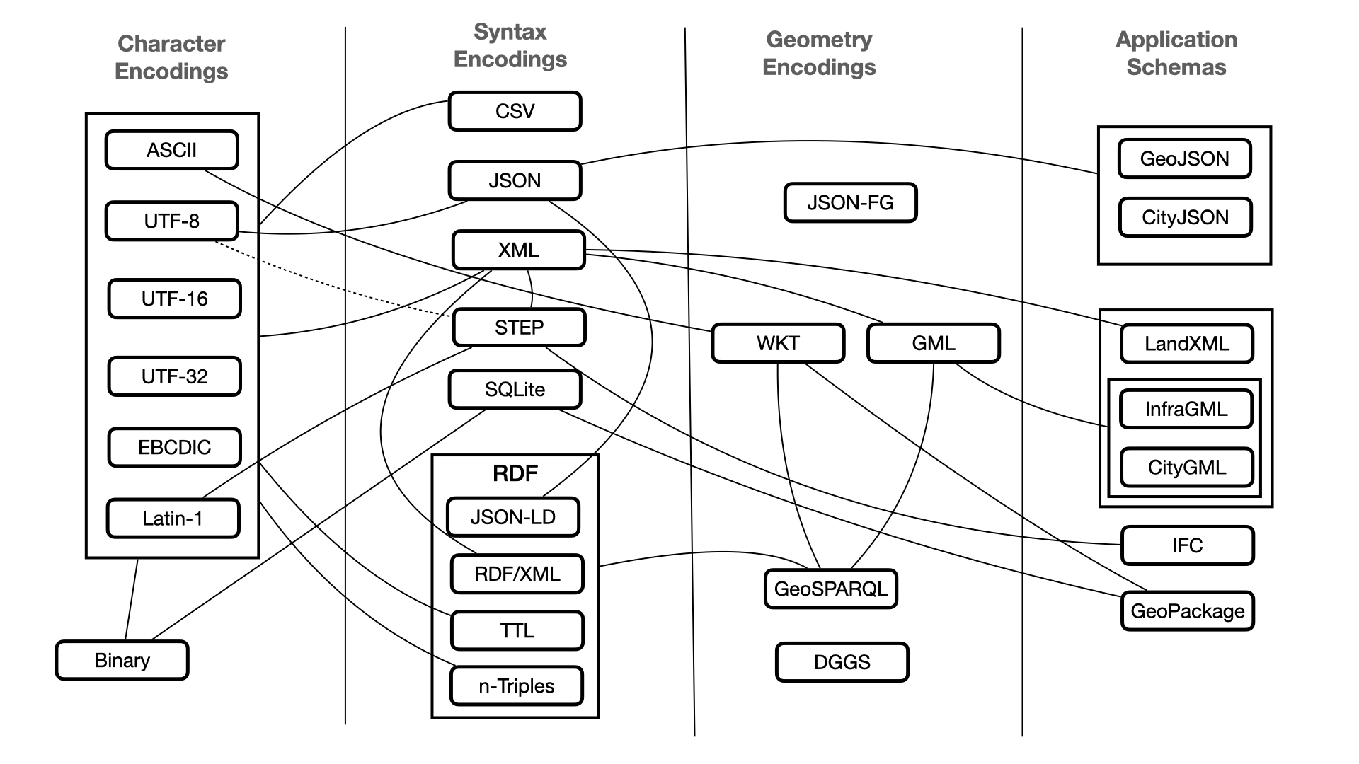
This Annex uses the categories described in this diagram to aid understanding of the type of encodings discussed. However, because capabilities and design decisions differ between encodings, the categorisations of encodings may be rough and open to interpretations.
-
Character Encodings - How symbols (letter, numbers, etc.) encoded in binary bits
-
Syntax Encodings - How to extract structure from a sequence of bytes
-
Geometry Encodings - Special encodings for spatial data types,
-
Application Schemas - File encodings suitable for consumption by software applications
-
Profiles - Specialisations of Application Schemas for more particular applications.
The primary focus will be on Syntax encodings and associated Application schemas. In addition, Geometry encodings will be discussed where pertinent.
Key Patterns
We base this analysis of encoding options largely on the patterns described in section 08-Patterns [link] of ICSM Conceptual Model for 3D Cadastral Survey Dataset Submissions . How well an encoding can fulfil these patterns determine suitability for implementations. We also look to future development plans for these encodings to determine who these standards may suit or may be influenced to suit the model’s requirements in the future.
Some of most important patterns to consider in this context include:
-
Modular Components [link]
-
Feature / Geometry Distinction [link]
-
3D Solid Geometry [link]
-
Topology of 3D Solids [link]
-
Domain Compatibility [link]
-
Linked Data Support [link]
An additional pattern of critical importance is Good Governance as discussed in Modular Components and detailed in A Digital Standards Governance Framework to Underpin New Zealand’s Infrastructure Data published by Building Innovation Partnership https://bipnz.org.nz/wp-content/uploads/2021/02/DataStandardsGovernace_Final_11Jan21.pdf Sustainability and continued interoperability of chosen encodings depend on effective governance of standards.
A particular key pattern expected to strongly influence encodings choices is Topology of 3D solids . We suggest a pathway to standardise this requirement in existing encodings while recognising the limitations of current software implementations.
Non-functional considerations include that encodings are well known, well-governed, and standardised implementations. These non-functional considerations provide the following benefits from the perspective of implementers of this specification:
-
confidence the model concepts can be encoded (since we can demonstrate candidate standard encodings for the most complex concepts)
-
take advantage of familiarity with one or more potential encodings
-
potential for reusable software libraries
-
interoperability of data elements across related application domains using the same encodings of the same common patterns
-
avoidance of a proliferation of ad-hoc approaches to common problems.
We suggest the establishment of standardised encoding implementations in cases where not published in a form suitable for a given encoding platform.
Application-specific vs. standardised encodings
There are many understandable reasons why a standard encoding of the concepts required to implement a 3D cadastre is not available and in widespread use:
-
Complex and comprehensive standards such as ISO 19107 may be faithful representations of the underlying theory but not easy to implement as encodings.
-
Standardised encoding approaches where available may also be challenging to use due to complexity and scope.
-
Many software systems pre-date suitable encoding standards.
-
It is relatively easy to implement an ad hoc solution for a narrow application scope.
For example, domain-specific XML schemas (such as LandXML) can quickly implement some key topology concepts using ad-hoc relationships between business objects:
<xs:element name="Boundary">
<xs:annotation>
<xs:documentation>The boundary region contains a 2D north/east or 3D north/east/elev list of points that define the geometry.</xs:documentation>
<xs:documentation>is identified by the "name" attribute.</xs:documentation>
<xs:documentation>If the "edgeTrim" attribute is true the faces are trimmed at the boundary edge, otherwise faces are not trimmed</xs:documentation>
<xs:documentation>and must exist entirely within the boundary.</xs:documentation>
</xs:annotation>
...The problem is that pacing more requirements on schemas, such as extensions to topology in 3D, increases the potential for variability of implementation patterns will grow, and the scope of software implementations narrow to specific applications that understand these particular relationships.
The goal of standardised encodings is so that multiple schemas from different domains implement common patterns in the same way. Data can thus be made interoperable, at least to the extent of the common patterns, between related domains. Software can be implemented for one domain and applied to other domains by applying the same patterns.
Another factor to consider is the evolution of the broader software technology environment.
What about BIM and CAD formats?
Our analysis led us to focus on GIS feature-centric encodings and exclude CAD formats such as DXF and DWG that are object and project centric. However, BIM formats, particularly IFC, can play important roles in sharing 3D cadastre datasets.

The most significant difference between GIS and CAD is how each collects and utilises data. The CAD technology designs elements that will be produced while GIS represent information of an area as it appears.
-
GIS is basically used to establish relationships between geographical objects and data. It captures analyses, stores, and presents geographical information to easily interpret. GIS uses layers of the same type and geometry to compare one layer against another.
-
CAD designs products of multiple components using 2D or 3D diagrams allowing designers to know how a building will be constructed. CAD formats like DXF and DWG vector graphics file formats are valid for exchanging engineering drawings. Still, they are limited in conveying data about features such as parcels, observations and measurements.
-
BIM inherits the CAD world perspective and extends the CAD approach into a multi-user, multi-discipline environment. It provides much of the backbone to Digital Twin environments.
It is important to note that most of the current software used by Cadastral surveyors fit more naturally in the BIM and CAD world than GIS. However, most land records offices store the cadastral fabric in GIS formats. Therefore, elements of the model will need to be implemented in both. To support this, the use of bridging ETL (extract, transform and load) software, such as FME from Safe Software, will likely become critical parts of the workflows at least for several years.
Overview of Syntax Encoding Technologies
This section provides an overview of Syntax Encoding options listed in the table below and includes discussions of the various related Format Encodings and Applications Schemas as suitable to the requirements of the model.
| Encodings | Governance | Modular components | Feature / Geometry Distinction | 3D Solid Geometry | Topology of 3D Solids | Domain Compatibility | Linke Data Support |
|---|---|---|---|---|---|---|---|
| Syntax | |||||||
| CSV | None - stable | Possible | High | ||||
| JSON | ISO/IEC - Strong | Possible | Possible | Possible | Medium | ||
| XML | IETF - Strong | Possible | Possible | High | Possible | ||
| STEP | ISO - Strong | Very High | Possible | ||||
| SQLite | Strong - Closed | Possible | Possible | Possible | Medium | Possible | |
| RDF | W3C - Strong | Possible | Possible | Medium | Very High | ||
| Geometry | |||||||
| JSON-FG | OGC - Strong - New | Developing | Possible | Low | Developing | ||
| GML | OGC - Strong | Possible | High | XLinks | |||
| WKT | ISO/IEC/OGC - Strong | Possible | Medium | via GeoSPARQL | |||
| GeoSPARQL | OGC - Strong | Medium | |||||
| DGGS | OGC/ISO - Strong | Medium | |||||
| App Schemas | |||||||
| GeoJSON | IETF - Strong | Minimal | Medium | ||||
| CityJSON | OGC - Strong - New | Possible | High | Low | |||
| LandXML | LandXML.org - Weak - Inactive | Possible | Possible | High | |||
| InfraGML | OGC - Strong | Possible | High | XLinks | |||
| CityGML | OGC - Strong | Medium | XLinks | ||||
| IFC | bSI/ISO - Strong | Very High | Developing | ||||
| GeoPackage | OGC - Strong | Possible | Developing | Developing | High | Possible |
CSV
A comma-separated values (CSV) file is a delimited text file that uses a comma to separate values. Each line of the file is a data record. Each record consists of one or more fields, separated by commas. The comma as a field separator gives this format its name. The use of other separators, typically tabs or semicolons, is common. We include variations with alternate separators such as TSV (tab-separated values) for this discussion. CSV as a data exchange format pre-dates personal computers and remains a widely used data exchange method.
A CSV file typically stores tabular data (numbers and text) in plain text, in which case each line will have the same number of fields. When used to store spatial data, each line is a feature with specific columns holding spatial values. The file structure is flat.
The CSV format is not fully standardised and generally only understood by the receiving application by prior arrangement. Profiling and validation tool support is weak to non-existent and challenging to normalise and extend. CSV is generally not recommended for encoding standardised Application Schemas for these and other reasons. But the export of at least portions of a 3D CSD may at times be valuable - particularly for less mature operations and organisations.
XML
XML (Extensible markup language) was designed to carry data, not to display data. It is a W3C recommendation. Extensible Markup Language (XML) is a markup language that defines a set of rules for encoding documents in a format that is both human-readable and machine-readable. The design goals of XML focus on simplicity, generality, and usability across the Internet. It is a textual data format with strong support via Unicode for different human languages. Although the design of XML focuses on documents, the language is widely used for the representation of arbitrary data structures such as those used in web services.
The advent of XML saw a move towards standardisation of data encoding from ad-hoc text, CSV and binary encodings to an environment where elements were parsable and could be directly referenced using standard approaches (e.g. XPath). A swath of implementation standards based on XML emerged, most notable the Geography Markup Language (GML). XML based data schemas present many advantages. Some of these are listed below
-
is human readable,
-
easily transported,
-
a well known and common format,
-
can be validated using a number of common toolsets,
-
through the use of XML Schema, data models can be reused, extended, partially documented, etc.
-
in line documentation is simple, providing developers instructions for modification
However, the use of XML is declining for a number of reasons. Using XML and developing XML application schemas presents its problems -
-
it is relatively complex and expensive to parse,
-
many find the additional rigour of XML schemas a significant burden or beyond reach
-
its extensibility model is limited and requires careful and explicit design of extension points, well beyond the skill of most practitioners,
-
it is verbose (although it compresses reasonably well) and data does not "self-document" well without both extensive XSD parsing and additional discipline in annotation of schemas (which is very uncommon).
The biggest drawback to XML within the developer community is that native XML parsing in Web clients is very difficult - XML parsers that can exploit XML schemas are large and difficult to use. These factors seem to be leading to a decline in the use of XML in the broader development community.
Yet XML remains the most common syntax encoding for sharing cadastral datasets despite these drawbacks. LandXML (including ePlan variants), CityGML, InfraGML, etc. are based on this syntax encoding. Most 3D Catastral data exchange research has been based on XML encodings. Current software vendors are familiar with XML. Therefore, XML based application encodings should be considered for near term implementations. Various existing XML encodings for geometry and application schemas are discussed later in this section.
JSON
JSON (JavaScript Object Notation) is a lightweight data-interchange format and is entirely language independent. It is based on the JavaScript programming language and is easy to understand and generate.
JSON is becoming increasingly popular over XML as an encoding format for geospatial data. Provided below is a comparison of the two technologies.
| JSON | XML |
|---|---|
|
It is JavaScript Object Notation |
It is Extensible markup language |
|
It is based on JavaScript language. |
It is derived from SGML. |
|
It is a way of representing objects. |
It is a markup language and uses tag structure to represent data items. |
|
It does not provides any support for namespaces. |
It supports namespaces. |
|
It supports array. |
It doesn’t supports array. |
|
Its files are very easy to read as compared to XML. |
Its documents are comparatively difficult to read and interpret. |
|
It doesn’t use end tag. |
It has start and end tags. |
|
It is less secured. |
It is more secured than JSON. |
|
It doesn’t supports comments. |
It supports comments. |
|
It supports only UTF-8 encoding. |
It supports various encoding. |
Developers are increasingly attracted to the lightweight, simple syntax and clear human and machine readability of JSON. As a result, JSON based application schemas for geospatial data, such as GeoJSON, have become very popular. But as many of these have been developed for particular communities, significant limitations exist that prevent broad use in more technical circumstances.
In the medium term, JSON is a vital encoding to consider for 3D Cadastral survey dataset submission. Several efforts are underway that remove many of the current limitations. FG-JSON and CityJSON are but two examples discussed in more detail below. When extended with the JSON-LD encoding, the additional advantages provided by RDF are made available.
Of particular note is the development by the OGC of a coherent suite of JSON based OGC APIs to modernise the XML-based OGC Web Services specifications.
The roadmap for developing these APIs is predicated on effective reuse of the logical constituents using JSON Schema.
STEP (ISO 10303-21:2016)
STEP is an ISO standard for the computer-interpretable representation and exchange of product manufacturing information. Its official title is: Automation systems and integration — Product data representation and exchange. It is known informally as "STEP", which stands for "STandard for the Exchange of Product model data". ISO 10303 can represent 3D objects in Computer-aided design (CAD) and related information.
STEP is the primary encoding for IFC Application Schemas. Implementations are currently limited to the BIM domain.
The international standard’s objective is to provide a mechanism capable of describing product data throughout the life cycle of a product, independent from any particular system. The nature of this description makes it suitable not only for neutral file exchange but also as a basis for implementing and sharing product databases and archiving. (ref- ISO 10303-1:1994 Industrial automation systems and integration — Product data representation and exchange — Part 1: Overview and fundamental principles)
As an ASCII-based format, one limitation of STEP is that the character encoding options are limited. However, work currently underway will provide UTF-8 support.
SQLite
The SQLite file format is stable, cross-platform, and backwards compatible, and the developers pledge to keep it that way through the year 2050. SQLite database files are commonly used as containers to transfer rich content between systems and as a long-term archival format for data. It is estimated that there are over 1 trillion SQLite databases in active use.
SQLite source code is in the public domain and is free to everyone to use for any purpose. Some advantages the SQLite database encoding approach provides include:
-
Normalised data
-
Easy to process and query
-
Skills personel are widely available
-
Can hold a variety of data types in one container
-
Easy to transport
Although open-source, participation in future development is closed to a small set of committed developers. But it is unlikely for the purposes of the 3D CSDM that this would be needed or useful.
The GeoPackge implementation schema encoding is built using SQLite. As an OGC project, participation in this work is more open. See discussion in the section GeoPackage
Resource Descriptor Framework
The Resource Descriptor Framework (RDF) is a World Wide Web (W3C) recommendation for data interchange on the Web. RDF has features that facilitate data merging even if the underlying schemas differ. In addition, it specifically supports the evolution of schemas over time without requiring all the data consumers to be changed.
Leveraging the linking structure of the Web, RDF extends the use URIs to name the relationship between things in addition to the two ends of the link (usually referred to as a “triple”). This technic allows structured and semi-structured data to be mixed, exposed, and shared across different applications.
This linking structure forms a directed, labelled graph, where the edges represent the named link between two resources, represented by the graph nodes. This graph view is the most accessible possible mental model for RDF and provides in easy-to-understand visual explanations.
Very simply, linked data is stored as triples that consist of a subject, predicate and object. These triples connect entities to other entities or literals to create a directed knowledge graph that consists of an object, predicate, and subject like a human language sentence.
RDF is expressed in several encodings. These include RDF/XML, N-Triples, Turtle (Terse RDF Triple Language or TTL) and JSON-LD. To view a good comparison of these encodings, go to https://medium.com/wallscope/understanding-linked-data-formats-rdf-xml-vs-turtle-vs-n-triples-eb931dbe9827.
There are advantages to each encodings. Turtle is increasingly popular and should be considered as a long term encoding. Advantages of this format are discussed at https://www.datasciencecentral.com/why-json-users-should-learn-turtle/. But, for the 3D CSDM encoding options we will focus on JSON-LD.
JSON-LD
JSON-LD promises to address two desires in data encodings simultaneously by supporting the use of both JSON and RDF.
JSON-LD is JSON, but has a few additional rules that help resolve the by reference problems. It does this in significant part by representing data in normal form (every distinct object is defined once and only once) but referencable multiple times. Specifically by: Defining a @context property that makes it possible to put data into different namespaces, which contain discrete buckets of properties based primarily upon functional type, Using globally unique identifiers (URIs) to identify concepts and entities. Creating datatype associations with atomic data types. Other items can be referenced from within JSON-LD, so long as they have global unique identifiers. This approach differs from most modern SQL databases (including SQLite), which maintain referential integrity within the scope of the database.
With these rules, JSON-LD annotates a JSON format with a recipe to turn schema elements into unambiguous Links (URI). The Linked Data part (-LD) refers to the expectation that these Web addresses resolve to a useful description, in both human and machine-readable data forms.
Recent experiences have shown that this emerging encoding strategy is compatible with the JSON schema used for GeoJSON. FG-JSON (discussed below) plans a JSON-LD encoding that extends GeoJSON capabilities.
The 3D CSDM, being built with semantic technologies, naturally lends to RDF outputs. Trends in the OGC and other SDOs currently focus on JSON-LD for the reasons above. So seeking implementations based on this encoding is appropriate for the near to mid-term. However, JSON-LD does possess some concerns for broader adoption. It sacrifices the simplicity of JSON, which displeases that community, and other RDF encodings, like TTL, are far simpler to implement and thus more attractive to the Linked Data community.
Geometry Encodings
Geography Markup Language - (ISO 19136:2007)
The Geography Markup Language (GML) is an XML grammar for expressing geographical features defined in ISO 19107. GML serves as a modelling language for geographic systems and an open interchange format for geographic transactions on the Internet. - https://www.ogc.org/standards/gml
The best practice for developing GML encodings (e.g. CityGML, InfraGML) is to create an XML schema (XSD) using the GML schema derived from a UML model based on ISO 19107. Exercising a "model driven architecture" (MDA) approach to generating GML is well established within the OGC. It does however require considerable expertise and tooling support. (for example, the SolidGround toolset by CSIRO).
GML is the language of the test canonical encoding presented in the Conceptual Model. It currently provides the most stable and usable implementation of the ISO19107 geometries. The limited support of xlinks offers some ability to normalise features and provide topological relationships. But xlink support is limited in the encoding and weak in tool support. RDF technologies would support data linking capability more naturally and broadly.
GML will continue to be supported and developed by OGC. Applications schemas most suitable for near term implementations rely on this standard. The current version, GML 3.3 was adopted in 2010. A proposal was made to start work on GML 4.0 in 2011 but was not initiated. (https://www.ogc.org/pressroom/pressreleases/1436) Some of the proposed improvements for this version included:
-
implement a more modular model
-
include better support for measurements
-
substitution of RDF for xlink to provide better data linking support,
-
support for more syntax encodings (JSON, RDF, etc.).
All these improvements would be helpful in the context of the 3D CSDM. But as the focus in OGC has moved to JSON based encodings, this project is unlikely to be revived. However, while this is not a path we recommend, the OGC work plan is driven by its members, so we could revive this effort if deemed valuable enough.
GML provides a stable base on which to build early implementations. We built the canonical reference implementation using this encoding. While GML 3.3 has drawbacks for long term use, we recommend its use for near term implementations.
Consequently, the recommendation is that this option is embarked on if, and only if, a normative GML encoding is deemed necessary and addresses the following concerns:
-
management and publication of UML and schema artefacts
-
UML representation of conceptual models
-
derivation and cross-referencing of UML application schema from a conceptual model
-
automation of MDA schema derivation and documentation processes.
-
testing of available tooling for implementation of required patterns.
-
development of translations to other formats.
-
data validation facilities.
Well-known Text (ISO/IEC 13249-3:2016)
Well-known text (WKT) is a text markup language representing vector geometry objects. The full name of the standard is ISO/IEC 13249-3:2016 Information technology — Database languages — SQL multimedia and application packages — Part 3: Spatial . A binary equivalent, known as well-known binary (WKB), transfers and stores the same information in a more compact form convenient for computer processing but not human-readable. The formats were initially defined by the Open Geospatial Consortium (OGC) and described in their Simple Feature Access. (https://www.iso.org/standard/60343.html)
As is indicated in the name, the primary use of WKT is the storage of spatial data within databases. This makes it useful for encodings such as GeoPackage. But it is also used by GeoSPARQL and others.
ISO/IEC 13249-3:2016 overlaps and extends ISO 19125 to support 3 (and 4) dimensions, curves, circular strings, etc. Instead of the ISO 19125 Simple Feature Access standard, it is feature-complete that defines standardised encoding only for 2-dimensional features.
WKT is a stable encoding standard. This standard was confirmed and reviewed in 2021 and remains current. By the ISO schedule, it will be next reviewed by 2026. There are no current work plans to update this standard.
The WKT encoding will likely have a role in future encodings of the 3D CSDM - mainly through database implementations such as GeoPackage and GeoSPARQL. As this is a stable standard, our recommendation is that usage issues be addressed by developing encodings such as those that implement WKT.
GeoSPARQL
Released in 2012 as an OGC standard, GeoSPARQL defines a vocabulary for representing geospatial data in RDF, and it defines an extension to the SPARQL query language for processing geospatial data. In addition, GeoSPARQL is designed to accommodate systems based on qualitative spatial reasoning and systems based on quantitative spatial computations. In particular, GeoSPARQL provides for:
-
a small topological ontology in RDFS/OWL for representation using
-
Geography Markup Language (GML) and well-known text representation of geometry (WKT) literals, and
-
Simple Features, RCC8, and DE-9IM (a.k.a. Clementini, Egenhofer) topological relationship vocabularies and ontologies for qualitative reasoning, and
-
-
a SPARQL query interface using
-
a set of topological SPARQL extension functions for quantitative reasoning, and
-
a set of Rule Interchange Format (RIF) Core inference rules for query transformation and interpretation.
-
Currently, GeoSPARQL is being reviewed for improvements. Some reasons include:
-
It’s too complicated — there are good use cases for simple geometry properties as in GeoRSS2007
-
It’s too simple — could be extended with more expressive properties and geometry types
-
It’s too diverse — would be nice to write queries just involving features and not "mess" with geometries if desired, rather than needing both semantic and geospatial expertise for every use.
Some of the suggested improvements include:
-
Support for more geometry encodings
-
Better ability to negotiate geometry serialisations
-
Improve semantic foundations
-
Additional geometry descriptors
-
Additional spatial query functions
-
Additional semantic geometric properties
-
Ability to extract simple dimensional extents
-
Additional simple geometric properties
-
(more info at https://www.w3.org/2015/spatial/wiki/Further_development_of_GeoSPARQL)
In the long term, we recommend using GeoSPARQL encodings, along with other RDF tools and encodings, to gain the advantages offered by linked data. Furthermore, we recommend participation in OGC GeoSPARQL SWG (https://www.ogc.org/projects/groups/geosparqlswg) to assure the needs of 3D CSDM are addressed.
FG-JSON
FG-JSON is a project of the newly chartered OGC Features and Geometries JSON SWG. It aims to provide a JSON encoding for geospatial feature data that -
-
builds upon the foundational OGC standards (such as Simple Features),
-
includes other geospatial JSON encodings (such as GeoJSON),
-
and supports content delivery per the OGC API suite of standards.
More specifically, JSON-FG will build on the widely used GeoJSON standard and add minimal extensions to support additional essential concepts for the broader geospatial community and the OGC API standards.
At a minimum, a more-inclusive JSON-FG should:
-
include the ability to use Coordinate Reference Systems (CRSs) other than WGS84,
-
support other non-Euclidean metrics, in particular ellipsoidal metrics,
-
support more geometry types, in particular solids, and
-
provide guidance on representing feature properties in JSON consistent with the General Feature Model, e.g., including temporal properties.
In the future OGC Features and Geometries JSON may be extended to include more complex geometries such as curves with non-linear interpolation, time-variant geometry, or geometries based on multiple coordinate reference systems.
Given the popularity of GeoJSON, the SWG will ensure that OGC Features and Geometries JSON will be specified as a superset of GeoJSON, so that valid GeoJSON is also valid OGC Features and Geometries JSON.
We recommend FG-JSON as a mid-term to long-term encoding option (depending on the development path). Work on this standard is ongoing and open to OGC members (and others to review and comment). Participation in the OGC Features and Geometries JSON SWG is advised to ensure that linked data and topology requirements of the 3D CSDM are addressed.
Discrete Global Grid System (DGGS)
A DGGS is a spatial reference system that uses a hierarchical tessellation of cells to partition and address the globe. DGGS are characterized by the properties of their cell structure, geo-encoding, quantization strategy and associated mathematical functions.The OGC DGGS Abstract Specification supports the specification of standardized DGGS infrastructures that enable the integrated analysis of very large, multi-source, multi-resolution, multi-dimensional, distributed geospatial data. Interoperability between OGC DGGS implementations is anticipated through implementation standards, and extension interface encodings of OGC Web Services.
A Brief Background into Discrete Global Grid Systems
The realisation of the "Digital Twin" will require the ability to integrate and represent the legal rights attached to property. This is why solving the semantic challenge posed by the 3D Cadastre is so important. However, this still leaves the challenge of searching, filtering and integrating the spatial representations of the 3D Cadastre in an efficient and scalable way. Discrete Global Grid Systems (DGGS) provide a way to do this without requiring all spatial data to be reprocessed and/or reprojected into an arbitrarily pre-determine geospatial reference frame.
DGGS are a spatial data infrastructure commonly defined by an equal-area hierarchical tessellation of the Earth with cell/zonal resolutions ranging from near global down to square-nanometre’s in size. Each cell/zone is referenced by it’s centroid and a globally unique identifier which facilitates rapid search, filtering, integration and analysis of spatial data at multiple scales and across multiple encoding formats anywhere on the globe.
"Surface" DGGS infrastructures are supported by ISO 19170-1:2021 (OGC Abstract Specification: Topic 21 - Part 1 v2.0). Work is currently underway through a Joint OGC-ISO-TC/211 activity to draft and publish additional parts to this standard to define:
-
Part 2: Three-Dimensional and Equal-Volume DGGS
-
Part 3: Spatio-Temporal DGGS
-
Part 4: Axis Aligned DGGS (i.e. cell/zone edges parallel to the axes of the underlying CRS)
Due to the 3D/4D nature of the Digital Twin and the 3D Cadastre data that supports it, surface DGGS infrastructures are of limited value because there is no partitioning of the vertical dimension. 3D (or Volumetric) DGGS, on the other hand, fill this gap quite nicely.
Despite the international standards defining 3D/4D DGGS still being in draft stage, there are already a number of early reference implementations of 3D DGGS infrastructures in development - one of which is available to the Surround Consortium through the TerraNexus DGGS platform being developed by Pangaea Innovations Pty. Ltd. . TerraNexus provides the 3D spatial indexing capability necessary to support topological search, filtering, integration and analysis of spatial data objects via index lookups instead of the more computationally intensive vector-based computations required by the conventional Feature-based approaches currently in wide usage.
A 3D Cadastre Scenario Example using a 3D Discrete Global Grid System
The potential of 3D/4D DGGS infrastructures to support Digital Twin use case scenarios can be demonstrated using a 3D Cadastre example. In this example a DGGS is used to select/highlight the intersection between a Cadastral parcel and a ground/terrain surface.
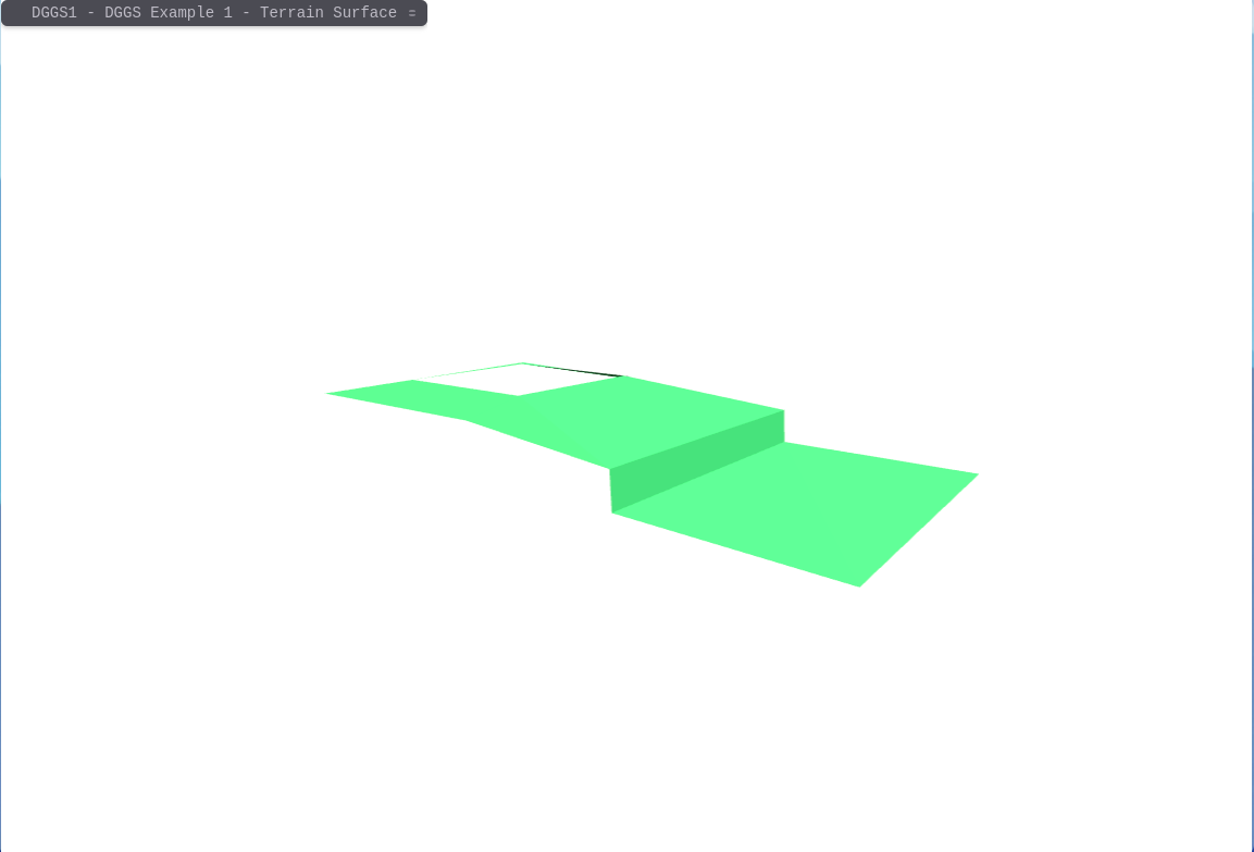
This terrain surface can be mapped by a 3D/4D DGGS in a number of ways. One way is to map the DGGS Voxels that are intersected by this surface.
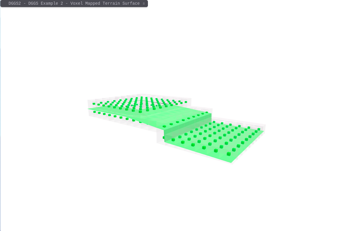
Another way is to map the solid volume extending from the terrain surface down to a given depth below ground. This, second method, provides a basis for the mapping of subterranean utilities and their relationship with surface building structures. Something that is of significant importance to the engineering and construction industry.
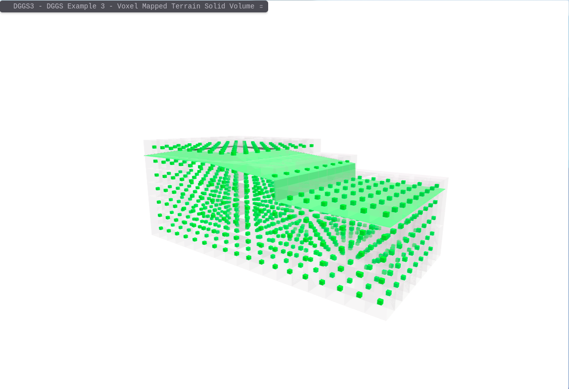
As with the subterranean volume case, mapping arbitrary solid bodies to a 3D/4D DGGS is the simple process of selecting DGGS Voxels in which their centroid is located inside the solid body. An example of this is the mapping of DGGS Voxels to the "Blue Box" Cadastral Parcel.
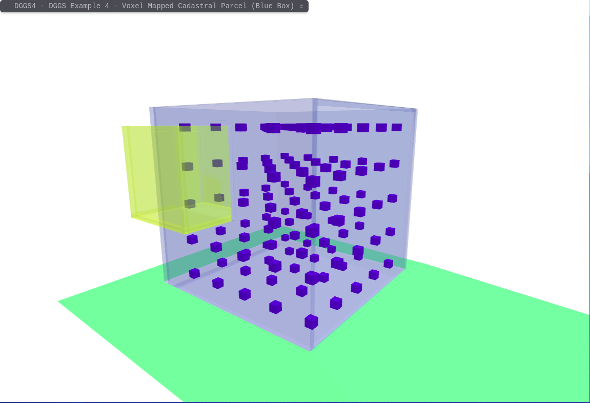
Once objects are mapped to a 3D/4D DGGS it is possible to find intersections between them by executing a database lookup operation to find DGGS Voxel indices that are mapped to all objects of interest. In this scenario, this is the "Blue Box" Cadastral Parcel and the Terrain Surface. This is contrasted against the necessity to perform repeated (and often complex) geospatial computations to achieve the same result using conventional GIS methods - which is why conventional geospatial filtering and aggregation techniques don’t scale very well, particularly as the region of focus expands from the building- to site- to city-scale.
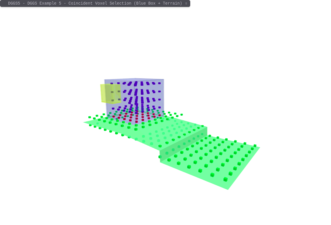
If you are just interested in the coincident DGGS voxels representing the intersection between the two objects this is achieved by returning just the DGGS Voxels that are mapped to both features.

The application of DGGS technologies to the 3D Cadastral and Digital Twin use case scenarios provides a much simpler, robust and repeatable way to manage and integrate both simple and complex features from multiple data sources at multiple scales. While this example only showed a single DGGS resolution, it is possible (and trivial) to perform these types of operations across multiple resolutions.
DGGS Encodings of Features
While it makes sense to store the DGGS representation of feature objects (such as Cadastral Parcels) in a database environment, to facilitate the efficient sharing and integration of data from disparate data sources across the web it is necessary to establish a set of standardised DGGS encoding exchange formats and schemas. Work is currently underway through the OGC to achieve this through the drafting of the OGC API - DGGS specification.
An example of what an OGC API - DGGS JSON response object for the "Blue Box" cadastral parcel and how it contrasts with a conventional OGC API - Features (JSON/GeoJSON) encoding might look like is as follows:
{
"type": "Feature",
"links" : [ (1)
{
"href" : "http://data.example.com/collections/buildings/items/bluebox?f=json",
"rel" : "self",
"type" : "application/geo+json",
"title" : "this document"
}, {
"href" : "http://data.example.com/collections/buildings/items/bluebox?f=html",
"rel" : "alternate",
"type" : "text/html",
"title" : "this document as HTML"
},{
"href" : "http://data.example.com/collections/buildings",
"rel" : "collection",
"type" : "application/json",
"title" : "the collection document"
}],
"id": "bluebox", (2)
"geometry": { (3)
"type": "GeometryCollection",
"geometries": [{
"type": "Polygon",
"coordinates": [[[38.089,-31.596,5.0], [38.089,-36.596,5.0], [43.089,-36.596,5.0], [43.089,-31.596,5.0], [38.089,-31.596,5.0]]]
},{
"type": "Polygon",
"coordinates": [[[38.089,-31.596,5.0], [38.089,-31.596,0.0], [38.089,-36.596,0.0], [38.089,-36.596,5.0], [38.089,-31.596,5.0]]]
},{
"type": "Polygon",
"coordinates": [[[38.089,-31.596,5.0], [38.089,-31.596,0.0], [43.089,-31.596,0.0], [43.089,-31.596,5.0], [38.089,-31.596,5.0]]]
},{
"type": "Polygon",
"coordinates": [[[38.089,-36.596,5.0], [43.089,-36.596,0.0], [43.089,-36.596,0.0], [43.089,-36.596,5.0], [38.089,-36.596,5.0]]]
},{
"type": "MultiPolygon",
"coordinates": [
[[[43.089,-36.596,5.0], [43.089,-36.596,0.0], [43.0893,-31.596,0.0], [43.089,-31.596,5.0], [43.089,-36.596,5.0]]], [[[43.089,-35.717,4.550], [43.089,-33.717,4.550], [43.0893,-33.717,2.530], [43.089,-35.717,2.530], [43.089,-35.717,4.550]]]
]},{
"type": "Polygon",
"coordinates": [[[38.089,-31.596,0.0], [43.089,-31.596,0.0], [43.089,-36.596,0.0],[38.089,-36.596,0.0], [43.089,-36.596,0.0]]]
}, {
"type": "Polygon",
"coordinates": [[[43.089, -35.717, 4.550], [42.252, -35.717, 4.550], [42.252, -35.717, 2.530],[43.089, -35.717, 2.530], [43.089, -35.717, 4.550]]]
},{
"type": "Polygon",
"coordinates": [[[42.252, -35.717, 2.530], [42.252, -35.717, 4.550], [42.252, -33.717, 4.550],[42.252, -33.717, 2.530], [42.252, -35.717, 2.530]]]
},{
"type": "Polygon",
"coordinates": [[[42.252, -33.717, 4.550], [43.089, -33.717, 4.550], [43.089, -33.717, 2.530],[42.252, -33.717, 2.530], [42.252, -33.717, 4.550]]]
}, {
"type": "Polygon",
"coordinates": [[[43.089, -35.717, 2.530], [42.252, -35.717, 2.530], [42.252, -33.717, 2.530],[43.089, -33.717, 2.530], [43.089, -35.717, 2.530]]]
}, {
"type": "Polygon",
"coordinates": [[[43.089, -35.717, 4.550], [42.252, -35.717, 4.550], [42.252, -33.717, 4.550],[43.089, -33.717, 4.550], [43.089, -35.717, 4.550]]]
},
}],
},
"properties" : { (4)
"function" : "residential",
"floors" : "2",
"lastUpdate" : "2015-08-01T12:34:56Z"
}
}-
Links to different data encodings
-
Feature object id
-
Geometry Representation of the Feature (e.g. the Blue Box)
-
Additional information associated with this Feature
The above representation of the "blue box" cadastral parcel only represents the spatial geometry of the object. To determine the slice through this geometry made by the terrain/ground (i.e. how much of the building is below ground surface level) requires a relatively computationally intensive calculation of the intersection of and arbitrary plane and an arbitrary solid object.
{
"type": "FeatureCollection",
"links" : [ (1)
{
"href" : "http://data.example.com/collections/buildings/dggs/{dggsRSID}/zones?{some query parameter operation request}&f=dggs+json",
"rel" : "self",
"type" : "application/dggs+json",
"title" : "this document"
}, {
"href" : "http://data.example.com/collections/buildings/dggs/{dggsRSID}/zones?{some query parameter operation request}&f=html",
"rel" : "alternate",
"type" : "text/html",
"title" : "this document as HTML"
}],
"numberMatched" : 123,
"numberReturned" : 1,
"features": [(2)
{
"type": "Feature",
"id": "bluebox", (2)
"geometry": { (3)
"type": "zoneList",
"geometries": ["R8813_-1", "R8816_-1", "R8819_-1", "R8813_-2", "R8816_-2", "R8819_-2", "R8813_-3", "R8816_-3", "R8819_-3", "R8813_-4", "R8816_-4", "R8819_-4", "R8813_-5", "R8816_-5", "R8819_-5", "R8821_-1", "R8822_-1", "R8823_-1", "R8824_-1", "R8825_-1", "R8826_-1", "R8827_-1", "R8828_-1", "R8829_-1", "R8821_-2", "R8822_-2", "R8823_-2", "R8824_-2", "R8825_-2", "R8826_-2", "R8827_-2", "R8828_-2", "R8829_-2", "R8821_-3", "R8822_-3", "R8823_-3", "R8824_-3", "R8825_-3", "R8826_-3", "R8827_-3", "R8828_-3", "R8829_-3", "R8821_-4", "R8822_-4", "R8823_-4", "R8824_-4", "R8825_-4", "R8826_-4", "R8827_-4", "R8828_-4", "R8829_-4", "R8821_-5", "R8822_-5", "R8823_-5", "R8824_-5", "R8825_-5", "R8826_-5", "R8827_-5", "R8828_-5", "R8829_-5", "R8831_-1", "R8834_-1", "R8837_-1", "R8831_-2", "R8834_-2", "R8837_-2", "R8831_-3", "R8834_-3", "R8831_-4", "R8834_-4", "R8831_-5", "R8834_-5", "R8843_-1", "R8846_-1", "R8843_-2", "R8846_-2", "R8843_-3", "R8846_-3", "R8843_-4", "R8846_-4", "R8843_-5", "R8846_-5", "R8851_-1", "R8852_-1", "R8853_-1", "R8854_-1", "R8855_-1", "R8856_-1", "R8851_-2", "R8852_-2", "R8853_-2", "R8854_-2", "R8855_-2", "R8856_-2", "R8851_-3", "R8852_-3", "R8853_-3", "R8854_-3", "R8855_-3", "R8856_-3", "R8851_-4", "R8852_-4", "R8853_-4", "R8854_-4", "R8855_-4", "R8856_-4", "R8851_-5", "R8852_-5", "R8853_-5", "R8854_-5", "R8855_-5", "R8856_-5", "R8861_-1", "R8864_-1", "R8861_-2", "R8864_-2", "R8864_-3", "R8864_-4", "R8864_-5',],
},
"properties" : { (4)
"function" : "residential",
"floors" : "2",
"lastUpdate" : "2015-08-01T12:34:56Z"
}
},
],
}-
Links to different data encodings
-
List of Features returned by the DGGS query of the collection.
-
DGGS ZoneList Geometry Representation of the Feature (e.g. the DGGS voxels that are mapped to the Blue Box)
-
Additional information associated with this Feature
The DGGS encoded object above represents the zonalID’s for the DGGS voxels that are mapped to the "Blue Box" cadastral parcel. Finding the intersection between the "Blue Box" and the terrain/ground surface is a much simpler and efficient database lookup type of operation to find matching DGGS zonalID’s which are mapped to both features. The result can then be transmitted via an encoding similar to the above where the geometry is implicitly represented by DGGS zonalID’s.
Application Schema encodings
GeoJSON - IETF RFC 5870
GeoJSON is a format for encoding data about geographic features using JavaScript Object Notation (JSON) [RFC7159]. Geographic features need not be physical things; anything with properties bounded in space may be considered a feature. GeoJSON provides a means of representing both the properties and spatial extent of features.
First published in 2008 at https://geojson.org, GeoJSON today plays a significant and growing role in many spatial databases, web APIs, and open data platforms. Consequently, the implementers increasingly demand formal standardisation, improvements in the specification, guidance on extensibility, and the means to utilise larger GeoJSON datasets.
The central focus of GeoJSON is to share spatial data for display in web maps. The GeoJSON development community is driven to maintain the simplicity of the standard to maintain focus on web developers who may not be geospatial professionals. Because of this focus, GeoJSON is very widely used. Also, because of this focus, previous efforts to include GeoJSON under the OGC umbrella (which consists of geospatial professionals) have failed. As a result, the OGC has recently launched the FG-JSON SWG, which aims to be GeoJSON compatible while extending it to provide the capabilities that geospatial professionals require.
Much of GeoJSON’s popularity derives from its simplicity, which makes it easy to implement, read, and share. So, like every other format, it has its limits.
GeoJSON has no support for 3D geometries. Only simple geometry types are supported. Users are limited to points, linestrings and polygons. GeoJSON has no construct for topology, whether for compression, like TopoJSON, or semantics, like OSM XML and some proprietary formats. A topological layer on top of GeoJSON is possible but unimplemented. GeoJSON features have properties, which are JSON. Properties can use any JSON datatype: numbers, strings, booleans, null, arrays, and objects. JSON doesn’t support every data type: for instance, date values, supported by Shapefiles, but not by JSON. GeoJSON doesn’t have a construct for styling features or specifying popup content like title & description. There are folk conventions, like simplestyle-spec and Leaflet’s Path properties, but these aren’t and won’t be part of the spec. Most geo formats don’t have styling support included either - KML stands out as prioritising styling. GeoJSON doesn’t have a circle geometry type, or any curve support. Only a few formats, like WKT, support curves and circles rather than straight-line geometries. Circles and curves are relatively tricky to implement, because a circle on a spheroid geoid planet is much more complex than a circle on a sheet of paper. Positions don’t have attributes. If you have a LineString representation of a run, and your GPS watch logged 1,000 different points along that run, along with your heart rate and the duration at that time, there’s no clear answer for how to represent that data. The Simple Features Specification, which directly inspired GeoJSON and most GIS formats, doesn’t support this notion of attributes-at-positions. GeoJSON specifies that the coordinate system is WGS84 except by prior arrangement, making it difficult to share data in other coordinates systems difficult. Furthermore, there is no support of dynamic datum information necessary to future 3D CSDM work.
Due to its inherent limitations, we recommend that the GeoJSON encoding be considered only for lightweight web map output. In the medium to long term, FG-JSON (discussed above) should be considered.
TopoJSON
TopoJSON is an extension of GeoJSON that encodes topology. Rather than representing geometries discretely, geometries in TopoJSON files are stitched together from shared line segments called arcs. This technique is similar to Matt Bloch’s MapShaper and the Arc/Info Export format, .e00.
TopoJSON eliminates redundancy, allowing related geometries to be stored efficiently in the same file. For example, a shared property boundary is represented only once rather than multiple times. A single TopoJSON file can contain numerous feature collections without duplication, such as states and counties. Or, a TopoJSON file can efficiently represent both polygons (for fill) and boundaries (for stroke) as two feature collections that share the same arc mesh. See How To Infer Topology for a visual explanation of how TopoJSON works. See Command-Line Cartography for an introduction to TopoJSON and related tools. See TopoJSON Format Specification for the format specification.
To further reduce file size, TopoJSON can use quantised delta-encoding for integer coordinates. This is similar to rounding coordinate values (e.g., LilJSON), but with greater efficiency and control over loss of information. And like GeoJSON, TopoJSON files are easily modified in a text editor and amenable to gzip compression. As a result, TopoJSON is substantially more compact than GeoJSON, frequently reducing 80% or more even without simplification.
We do not recommend TopoJSON as an application schema encoding option despite these advantages. This is because TopoJSON shares many of the weaknesses of GeoJSON discussed above. Also, TopoJSON lacks a clear governance structure and the project appears inactive. The TopoJSON repository (https://github.com/topojson/topojson) has not had code updates since 2017. Instead, we recommend involvement in the OGC FG-JSON SWG to ensure that the advantages offered by TopoJSON are included in this new encoding.
CityJSON
CityJSON is a new standard that encodes a subset of version 3.0.0 of the OGC CityGML conceptual data model (discussed below). The few CityGML features not currently supported are either because they are seldom used or would overcomplicate the JSON encoding. Dispite this, bidirectional conversion between CityJSON and CityGML is possible. Like CityGML on which it is based, the new application schema CityJSON provides storage of 3D city models, also called digital twins ( but built on JSON rather than XML. (https://www.cityjson.org)
CityJSON aims to offer a compact and developer-friendly application schema encoding to share, visualise, manipulate, and edit files easily. Designed with developers in mind, tools and APIs supporting it can be quickly built, and several are available (most as open-source).
The CityGML 3.0 conceptual model on which CityJSON is the first encoding, offers multiple advantages over older versions of CityGML. Better alignment with IFC is but one. This is discussed in more detail in the CityGML section of this encodings review.
Limitations inherent in CityJSON are similar to those of JSON and CityGML. There is currently a lack of topology and linked data support. While one could easily use this format to portray property boundaries in 3D, it is not particularly useful for submitting 3D Cadastral observations.
We recommend that CityJSON be explored as an encoding option for near to middle term implementations of some portions of the 3D CSDM. As it is unlikely that CityJSON would provide a complete solution, implementers should carefully determine where this standard would be most beneficial. Digital Twin support is one example.
LandXML
LandXML, launched in July 2000, is a specialised XML data file format containing civil engineering and survey measurement data commonly used in the Land Development and Transportation Industries in many parts of the world. LandXML was developed to enable data transfer and long term data archiving. It is now a standard format of digital submission in the industry. Within our region, there is extensive use of LandXML in the cadastral surveying domain across Australia and New Zealand. Many common CAD software packages in use by surveyors support LandXML, including 12D, CivilCAD, AutoCAD and Trimble business Centre.
ICSM has endorsed LandXML as the recommended standard for digital lodgement of cadastral plans.
LandXML was selected mainly because of the use of LandXML by New Zealand in its digital lodgement, but also from feedback within Australia {Intergovernmental Committee on Surveying and Mapping, 2010 #14}.
The LINZ Land on Line requires submission of plans to be in compliance with a profile of this application schema.
At least one software vendor (12D) has supported the LINZ profile.
The Australian ePlan specifies a profile of this encoding as well. However, unlike the New Zealand LandOnLine system, the use of this encoding has not been mandated.
In our review of previous related research, we note that various parties have investigated the prospect of basing a 3D cadastre on LandXML based encodings.
However, the use of LandXML for 3D CSDM submission presents major difficulties -
-
LandXML support for 3D Solid Geometry and Topology is limited. While z coordinate values are supported, solids are not.
-
LandXML lacks a conceptual model. This was why OGC decided to progress LandInfra rather than adopt LandXML as an OGC endorsed community standard.
-
Governance of the LandXML standard is very weak. This has led to a proliferation of incompatible profiles. Continued use for the cross government purposes of the 3D CSDM would incur significant governance overhead - most likely on ICSM. Such a situation would lessen the desirability of software providers to implement.
We recommend that support for LandXML be provided in the short term, at least as an export format, to support existing software capability to import this encoding. While this support tends to be quite limited, LandXML is currently more broadly supported than any other contending application schema other than IFC.
InfraGML
This OGC InfraGML standard is an XML encoding of the OGC LandInfra conceptual model. Geometry is provided through the use of GML 3.3. LandInfra is currently the most complete model available that addresses the concerns of the 3D CSDM project and the source of much reference material for the 3D CSDM standard.
The InfraGML Encoding Standards present an implementation-dependent, GML encoding of concepts supporting land and civil engineering infrastructure facilities as specified in the OGC Land and Infrastructure Conceptual Model Standard (LandInfra), OGC 15-111r1 It is a multi-part standard of 7 parts. The parts of most interests to this project are:
-
Part 6 addresses the Survey, Equipment, Observations and Survey Results Requirements Classes from LandInfra, and
-
Part 7 addresses the Land Division and Condominium Requirements Classes from LandInfra.
The future development of these parts is closely aligned to the continued development of the Land Administration Domain Model (LADM - ISO19152) - particularly LADM Part 2, currently under development.
InfraGML has been deployed by at least one major relevant software vendor (Leica). Major software vendors were deeply involved in creating this standard, so the hope is that more adoptions will follow.
Despite this, we have not found InfraGML wholely suitable with the 3D CSDM for various technical reasons. Some of these include poor 3D Topology support and improper alignment with the Observations model. Therefore, we have been in discussions with the technical lead of the OGC LandInfra DWG about how we can improve this standard in the near future.
We recommend that InfraGML be supported once the standard has become compatible with the 3D CSDM. We advise Participation in the LADM and LandInfra working groups to facilitate this work.
CityGML
The CityGML standard utilises GML encoding to define a conceptual model and exchange format for the representation, storage and exchange of virtual 3D city models. It facilitates the integration of urban geodata for a variety of applications for Smart Cities and Urban Digital Twins, including urban and landscape planning; Building Information Modeling (BIM); mobile telecommunication; disaster management; 3D cadastre; tourism; vehicle & pedestrian navigation; autonomous driving and driving assistance; facility management, and; energy, traffic and environmental simulations.
CityGML 3.0 is an evolution of the previous versions 1.0 and 2.0 of CityGML. While the earlier versions standardised a GML exchange format, CityGML 3.0 standardises the underlying information model and can be implemented in various technologies, including GML. The CityGML 3.0 Conceptual Model Standard describes a common semantic information model for the representation of 3D urban objects. The model’s primary function is to define the human interpretation of modelled data objects as well as their geometric representation and relationships. The CityGML 3.0 Conceptual Model provides a framework for integrating, storing, and exchanging 3D geospatial data.
CityGML 3.0 allows data to be encoded in GML/XML and JSON or database schemas. Additional benefits compared to previous versions include:
-
much better integration with BIM,
-
the ability to represent indoor spaces in different Levels of Detail (LOD),
-
support for dynamic data provided by sensors and simulations,
-
and the capability to extend the information model into Application Domain Extensions using Model Driven Architecture tools.
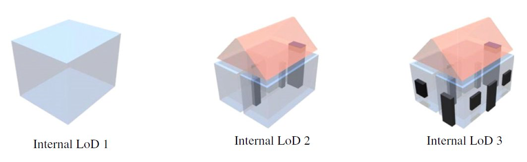
Currently, both GML and JSON encodings for CityGML 3.0 is available for practical use. CityJSON is discussed above. The respective XML schema files can be downloaded from here: https://github.com/opengeospatial/CityGML-3.0Encodings/releases A CityGML 3.0 GML Encoding specification document is under development and will be issued as a separate encoding standard in due course. As many datasets using both CityGML 1.0 and 2.0 have been created and are in active use, these specifications will not be deprecated. However, existing data can be upgraded to CityGML 3.0.
Industry Foundation Classes (ISO 16739-1:2018)
Industry Foundation Classes (IFC) are a standardised, digital description of the built asset industry. Typically these are implemented using STEP encoding (ISO10103-23).
With the increased use, and in some jurisdictions (e.g. United Kingdom) the mandating, of Building Information Management (BIM) models to document and describe both the planned and "as built" construction of urban projects, there is an increasing requirement for cadastral information to be recorded and presented in a format that is compatible with BIM models. This is commonly achieved through the use of IFC. The IFC data model and encoding, developed by buildingSMART International, is a standardised, digital description of the built environment, including buildings and civil infrastructure. It is an open, international standard (ISO 16739-1:2018), meant to be vendor-neutral or agnostic, and usable across a wide range of hardware devices, software platforms, and interfaces for many different use cases.
While not specifically designed for cadastral use cases, IFC does include a number of appropriate classes to describe both cadastral parcels and building occupations. In addition, IFC can provide a useful transfer encoding for 3D Cadastral information that can integrate with existing BIM software used in the Architectural, Engineering and Construction (AEC) industry.
Although the scope and requirements for IFC and Cadastre are very different there are a number of key areas where compatibility can be supported:
-
testing translation of 3D solid geometry elements into IFC "Spaces"
-
use of IFC models to describe Occupation details of surveyed boundaries
The extensive use of the IFC standard has been a prime consideration in developing the 3D CSDM model. The testing framework for the 3D CSDM includes translating canonical examples into IFC equivalent forms, particularly for viewing example data. However, IFC does not readily support the identified cadastre domain requirements, such as observations about survey points and vectors and metadata around survey processes. Still, compatibility of IFC with the 3D CSDM provides for ready integration of data between design and survey spaces.
The current development of IFC 5 holds much promise. To guarantee a new future proof IFC, the schema aims to:
become predictable and consistent (to become stricter and easier during implementation); be based on methodologies that have an equivalent in multiple, modern computer interpretable languages like XSD, OWL and JSON ; remove circular references and possibly add identifiers to entities that don’t have any now; become modular to facilitate additional domains and extensions.
When combined with similar efforts underway in CityGML, the future ability of IFC to interoperate with other 3D CSDM encodings and systems should become much more tractable.
Therefore, because of the vast amounts of related 3D data held in BIM formats and the broad support of this format by current software providers, we recommend IFC 4 as a near term encoding for appropriate parts of the 3D CSDM. Furthermore, we recommend engagement with the bSI efforts to develop IFC 5 to support future 3D CSDM implementations.
GeoPackage
The OGC GeoPackage data encoding provides an SQLLite database implementation of the OGC Simple Features SQL specification. GeoPackage is an open, standards-based, platform-independent, portable, self-describing, compact format for transferring geospatial information. A GeoPackage, in essence, is an SQLite container with OGC encoding standards for storing vector features, tile matrix (raster data), non-spatial attributes data and extensions.
GeoPackage advantages include: Open source, based on SQLite database Very lightweight but highly compatible across environments (esp. in mobile devices where connectivity & bandwidth is limited) Geopackages are almost 2x lighter than GeoJSON files because data can be normalised (and thus provide basic topology). Since the vector layers in GeoPackage are inherently rtree spatially indexed, loading and queries are fast. There is no limit on the file size. A single GeoPackage file can contain multiple layers, with each layer having a different geometry type. Can hold non-spatial attribute tables (pandas tables) alongside vector layers. The file can be managed using a wide variety of GIS tools as well as Python, R, SQLite and Postgres (with few limitations on each mode) Adding and loading to a Postgres database is much faster than GeoJSON since it is already a database format and spatially indexed. Interestingly, GeoPackages can also handle rasters as a tile matrix. (of course, there are some limitations to this)
Currently, 3D support is weak in GeoPackage. 3D extensions may emerge but are not yet visible at https://www.geopackage.org/extensions.html. "Smuggling" 3D geometries into textual attributes as a microformat is probably achievable, but such a non-standardised solution is not advised. Furthermore, any such approach would require formalisation to avoid the proliferation of incompatible solutions. Until such formalisation occurs, such forms are probably more relevant for "direct use" than data exchange as they are difficult to self-document and perform localised validation steps against specific aspects.
However, GeoPackage is an active project that seems open to such work. Recent annual OGC Testbeds commonly contain a component of work that leads to extensions added to GeoPackage.
We recommend the exploration of GeoPackage as a 3D CSDM encoding stand in the medium term. Compatibility with mobile devices is a particular area of concern expressed by software vendors. GeoPackage, being SQLite based, works well in these environments. The ability to hold multiple files of different types in one GeoPackage is an advantage to 3D CSDM implementations worth exploring.
Mapping Use Case 7 Requirements to Existing standards
The preceding encoding options analysis focuses on the requirements of submitting cadastral boundary and observation information. In contrast, Use Case 7 consists of the 3D CSDM metadata (header) requirements - these tell the story behind the data and include who, what, when, why and how details necessary to understand the meaning and context of a 3D CSDM fully. Such information may not be included in the measurement data themselves or may need to be accessed separately. UC7 does not cover all header requirements. Some, such as units and measurements, are more appropriately included in other use cases.
The general finding is that various existing candidate encoding standards may support none, some or nearly all the identified requirements. This section of the document details these findings. Of the standards reviewed, only LandInfra came close to supporting all the requirements captured in UC 7. All options would require a companion standardised metadata record to hold some information. To support the cataloguing and discovery of data, we recommend a companion metadata record as best practice regardless of the encoding. Here we use ISO 19115 parts 1 and 2 to illustrate.
Preconditions Mapping
| Use Case Prerequisite | LandInfra | IFC 4 | CityGML | LADM | iso19115 (-1 and -2) |
|---|---|---|---|---|---|
|
7.0-1 Administrative area |
::Feature::LandDivision::AdministrativeDivision |
n/a? |
n/a? |
::LA_AdministrativeParty(::LA_AdministrativePartyRoleType=stateAdministrator) |
:: MD_DataIdentification::MD_Keywords:keywordwith :keywordClass |
|
7.0-2 CSD Status Dates |
::Feature::Project::projectStatus and LandInfra::Feature::Project::projectStatus |
n/a |
n/a |
::LA_StatusTypeAlso see::ExtArchive (for registration recording) |
::MD_DataIdentificationand::LI_Lineage::LI_ProcessStep |
|
7.0-3 CSD Description |
::Survey::description and/or LandInfra::Survey::purposeOfSurvey |
IfcContext:Description |
n/a? |
::LA_SurveyPurpose?? |
:: MD_DataIdentification:abstract |
|
7.0-4 Surveyor Certification |
::Survey::landSurveyor |
ifcActor |
n/a |
::LA_SurveyParty |
::MI_AcquisitionInformation::MI_Requirement |
|
7.0-5 CSD Generation Method |
::LandInfraDataset:application |
n/a? |
n/a |
::LA_SurveySource::platform::LA_PlatformType |
::MI_AcquisitionInformation::MI_Platform |
|
7.0-6 Survey Network Connection (CRS) (See 7.3) |
::LandInfraDataset:defaultCRS |
gml:srsName? |
::SC_CRS (from ISO19111) |
::MD_ReferenceSystem |
|
|
7.0-7 Survey Equipment Details (See 7.2) |
::Survey::Equipment |
n/a |
n/a |
n/a |
::MI_AcquisitionInformation::MI_Instrument |
|
7.0-8 Survey Point Quality |
::SurveyResults:: PointQuality |
?? |
n/a? |
::LA_Point(OM_Observation:resultQuality) |
:;DQ_DataQuality |
|
7.0-9 Survey Report |
(see 7.1-3) |
ifcDocumentation |
n/a |
?? |
::MD_DataIdentification::MD_AssociatedResource |
|
7.0-10 Survey Type |
::Survey::type |
n/a |
n/a |
::LA_SpatialSourceType |
::MD_DataIdentification::MD_Keyword:keywordwith:keywordClass |
|
7.1-1 Field Record |
::Feature::documentas ::Survey::fieldNote See link |
IfcContext:Ifc:RelAssociatesDocument:IfcDocumentation |
n/a |
?? |
::MD_DataIdentification::MD_AssociatedResource |
|
7.1-2 Survey Adjustment Report |
::Feature::document consist of::Survey::Equipment::ObservationCalibrations |
n/a |
n/a |
::LA_Transformation? |
::MI_AcquisitionInformation::MI_Operation |
|
7.1-3 Survey Report |
::Feature::document |
ifcDocumentation |
n/a |
?? |
::MD_DataIdentification::MD_AssociatedResource |
|
7.1-4 Corespondence |
::Feature::document |
ifcDocumentation |
n/a |
?? |
::MD_DataIdentification::MD_AssociatedResource |
|
7.2-1 Equipment Used |
::Survey::Equipment::description |
n/a |
n/a |
n/a? |
::MI_AcquisitionInformation::MI_Instrument |
|
7.2-2 Instrument Manufacturer |
::Survey::Equipment;dataCollector |
n/a |
n/a |
n/a |
::MI_AcquisitionInformation::MI_Instrument |
|
7.2-3 Instrument Model |
::Survey::Equipment;dataCollector |
n/a |
n/a |
n/a |
::MI_AcquisitionInformation::MI_Instrument |
|
7.2-4 Instrument Serial Number |
::Survey::Equipment::serialID |
n/a |
n/a |
n/a |
::MI_AcquisitionInformation::MI_Instrument |
|
7.2-5 Firmware Version |
::Survey::Equipment::controlSoftware and::Survey::Equipment::softwareVersion(or under SurveySensor?) |
n/a |
n/a |
n/a |
::MI_AcquisitionInformation::MI_Instrument |
|
7.2-6 Instrument Calibration |
::Survey::Equipment::SurveySensor::Calibration |
n/a |
n/a |
n/a |
::MI_AcquisitionInformation::MI_Instrument |
|
7.2-7 Instrument Constants |
Multiple under -::Survey::Equipment::SurveySensor??? |
n/a |
n/a |
n/a |
::MI_AcquisitionInformation::MI_Instrument |
|
7.2-8 Instrument Specifications |
Multiple under -::Survey::Equipment::SurveySensor???Depends on type? |
n/a |
n/a |
n/a |
::MI_AcquisitionInformation::MI_Instrument |
|
7.3-1 Survey Orientation (CRS) |
::LandInfraDataset:defaultCRS |
IfcCoordinateSystem |
gml:srsName? |
::SC_CRS (from ISO19111) |
::MD_ReferenceSystem:referencesystemIdentifierwith:referenceSystemType |
|
7.3-2 Vertical Datum |
(Missing? or part of CRS?) |
IfcCoordinateSystem:VerticalDatum |
gml:srsName? |
::SC_CRS (from ISO19111) |
::MD_ReferenceSystem:referencesystemIdentifierwith:referenceSystemType |
CityGML
We have identified few elements in CityGML 2 or 3 suitable to capture the requirements of UC7. However, external metadata using standards such as iso19115-1 can provide much of the needed functionality. In addition, it is common practice to attach such metadata records to geospatial datasets such as CityGML.
IFC
The Industry Foundation Classes Standard, commonly supported by BIM software packages, has limited support for UC 7 requirements. Our findings are that ifcContext is the most appropriate class to contain most of this header information. As stated in the official document IFC4_ADD2_TC1 - 4.0.2.1:
“All project data sets shall contain a single IfcProject instance indicating overall context and a directory of objects contained within. The context definition may include:
the default units the geometric representation context for the shape representations the global positioning of the project coordinate system the reference to classification systems, or other external information sources, used the registry of object types and property templates used in the project context”
However, as with CityGML, many of the requirements of UC 7 cannot be supported using IFC alone. External standardised metadata would be needed to use IFC as the underlying data exchange format.
LADM
The Land Administration Domain Model (ISO 19152) is currently under review. For this exercise, we have chosen to map to the new version and part, NP ISO 19152-2:20xx(E) Second edition 2016-06. Part 2 in the revision of the standard focuses on Land Registration, including surveying elements. An anticipated completion date for this work is scheduled for 2024.
LADM is a conceptual schema only. However, alignment with LandInfra is strong, and InfraGML is considered a valid implementation schema for this portion of the LADM. Therefore we will look to InfraGML for encoding options.
InfraGML
The LandInfra conceptual model and, by extension, the InfraGML encodings support almost all of the requirements of UC 7. The LandInfraDataset class can hold much of this content. This class is designed to contain header information (metadata) about LandInfra datasets. Close matches for all requirements (save one - Vertical Datum) can be found in the classes provided by the LandInfra model.
ISO19115-1 and ISO19115-2
Separable metadata is a recommended best practice for any encoding to support data management and discovery. There are several standards available to support this task. In this review, we have chosen to illustrate ISO19115-1 (Fundamentals) and ISO19115-2 (Extensions for acquisition and processing) as illustrated in the table. ICSM strongly endorses ISO19115-1 for the cataloguing of spatial data. The ISO 19115 series is currently the most robust and mature of such standards in this domain.
The Evolution of the Wider Software Technology Environment.
The current trend in the wider world is XML being largely superseded by the easier to parse (and natively supported) JSON format - with a similar nested tree structure, but fewer restrictions on element order, cardinality and support for lists.
For more information about this trend there are many discussions such as A Deep Look at JSON vs. XML, Part 1: The History of Each Standard and JSON vs XML (w3schools.com, December 2016)
At the time (2019) of these discussions, a key message was "The fundamental deficiency of JSON is its lack in providing a general standard for the normative description of the logical constituents of its documents."
Nevertheless, its simplicity of implementation is leading to a proliferation of JSON formats proposed for related applications:
-
GeoJSON
-
CityJSON
-
FG-JSON
Longer-term, this landscape becomes less clear. The slow-moving but undeniable trend to linked data will inevitably lead to preferences of datatypes supporting RDF. In the near term, JSON-LD seems natural. However, JSON-LD does possess some concerns for broader adoption. It sacrifices the simplicity of JSON, which displeases that community, and other RDF encodings, like TTL, are far simpler to implement and thus more attractive to the Linked Data community. For a discussion of the advantages of TTL, see https://www.datasciencecentral.com/why-json-users-should-learn-turtle/.
Profiling and the ISO 19107 Geometry and Topology
Examining the history of implementation of spatial standards leads to the conclusion that implementations tend to implement subsets of more general conceptual models . They are sometimes identified explicitly as profiles and sometimes implicitly via commentary in documents.
For example the scope of the GeoJSON specification is described this way:
GeoJSON supports the following geometry types: Point, LineString, Polygon, MultiPoint, MultiLineString, and MultiPolygon. Geometric objects with additional properties are Feature objects. FeatureCollection objects contain sets of features.
These concepts are not defined, and neither the machine readable artefacts nor does the IETF specification make explicit reference to the ISO19107 or GML specifications, yet clearly these terms are grounded in these concepts.
GML is an XML encoding that implements a broad range of ISO 19107 (Edition 1) concepts but is not completely aligned with ISO 19107 (Edition 2) ( for example, the Simplicial Complex geometry introduced in Edition 2 is not represented explicitly in Edition 1)
However, the complexity of GML is managed in practice by a suite of GML Simple Features Profiles (Levels 0,1,2). Many software libraries support only GML Level 0, and often in a further (undeclared) restriction to 2-dimensions.
The current state of implementations of ISO19107 across a range of different profiles and encoding options illustrates the gap between advanced 3D support in ISO 19107 and existing encodings.
Suggested Roadmap
In order to minimise long-term risks it is proposed to develop an implementation strategy predicated on alignment with:
-
Encoding preferences of existing software providers and their appetite for change
-
Wider community trends towards JSON (developers) and IFC (Digital Twins)
-
Emergence of FG_JSON, and possible JSON-LD extensions
-
Evidence for and ongoing exploration of potential RDF based encodings
-
The OGC API roadmap
-
Development of GeoSPARQL 1.2 as a joint ISO/OGC standard
-
OGC activities towards improving practices around conceptual model publication
-
Consolidation of the proliferation of informal profiles of ISO 19107
The current suite of encoding options may be visualised:
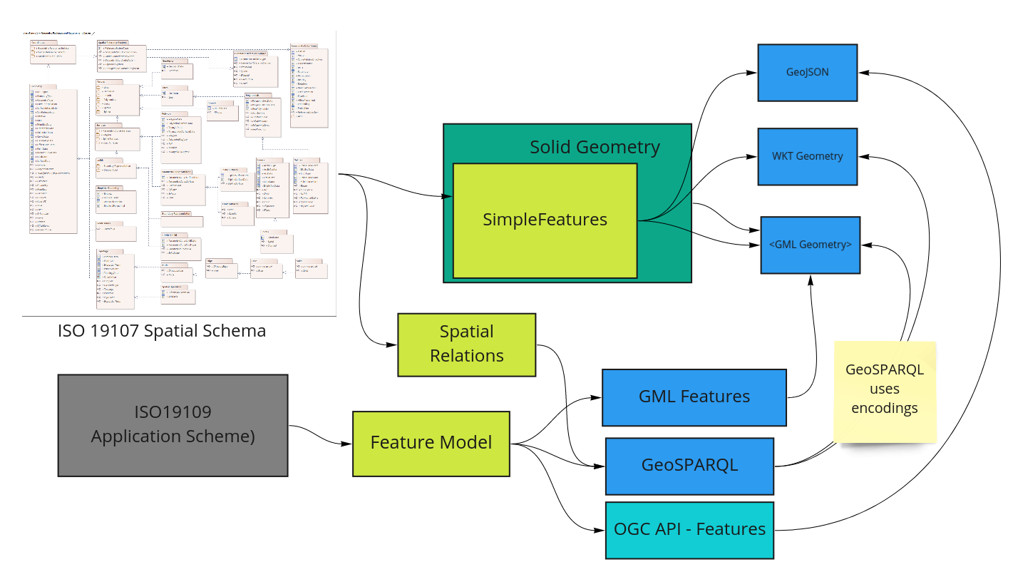
Noting:
-
GeoJSON uses an informal subset of GML Simple Features (Multi-) Points, Lines and Polygons..
-
CityGML uses an informal subset of GML for 3D geometry
-
Industry Foundation Classes (IFC) support is facilitated through the use of the STEP data exchange file encoding standard ISO-10303-21:2016. The specific IFC objects used for an IFC file encoding are defined by ISO 16739-1:2018.
Towards an optimal set of encoding options
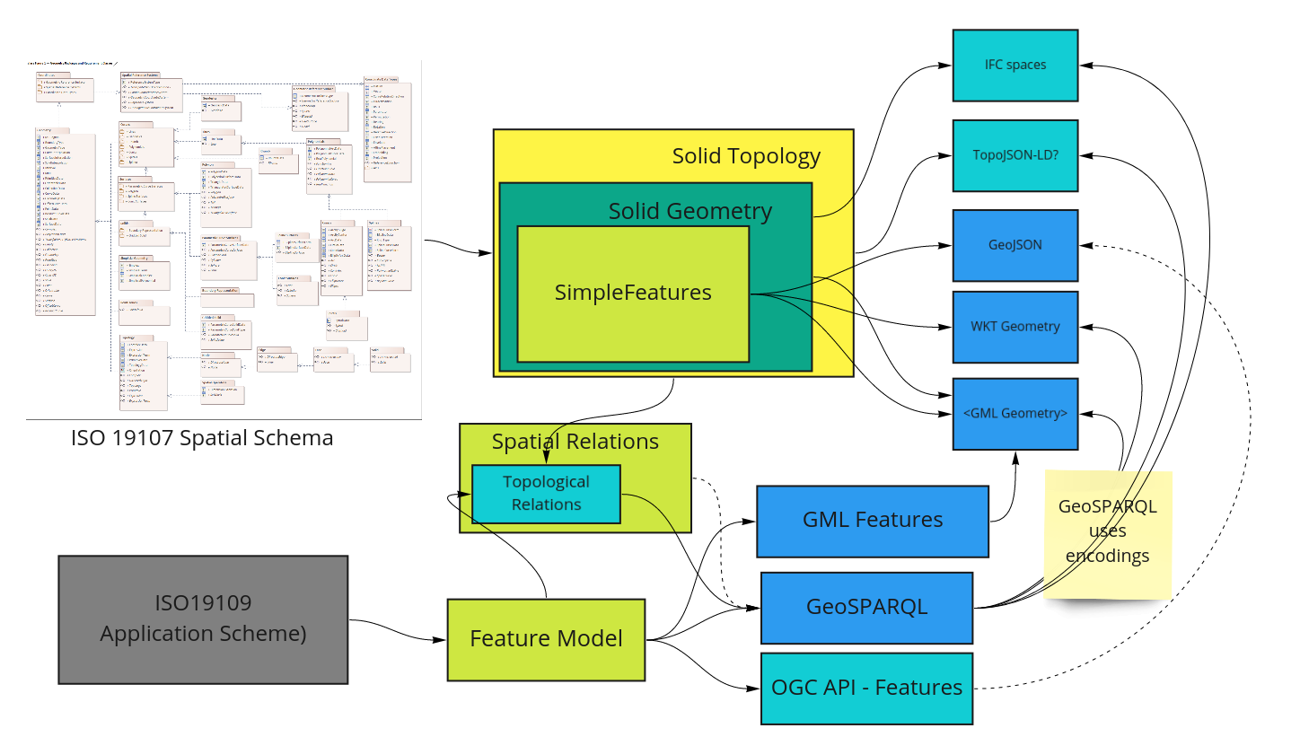
Related Standards Review Road Map
For a data model to be sustainable and implementable, it must be aligned to existing well-known standards whenever possible. However, when existing standards do not support the requirements, the existing standards may need to be altered or discarded in favour of other standards. Since many consortia members are involved in standards bodies relevant to this work, we can understand the suitability and reliability and influence the development of standards on which the model relies and must interact.
Standard choices exist in many aspects of this project, from the language of the data model to the encoding standards used by applications supporting the standard. Beyond fitness to requirements, our review included how well-governed the standards are and how open they are to participation. At the implementation level, we sought out standards that existing software vendors are familiar with and willing to implement. Where the choice exists, we preferred simple, unambiguous standards to decrease implementation differences.
Our standards review includes a continuing watch of the status of significant standards and future trends. We can nominate a consortia member currently involved or peripherally involved for most of these activities to champion 3D CSDM needs.
-
ISO19107 - Improve 3D support - Rob Atkinson
-
ISO19152 - LADM - Merge findings with Part 2 continuing development - Andrew Hunter
-
OGC LandInfra (InfraGML) - Incorporate findings, improve alignment with O&M - Byron Cochrane
-
GeoSPARQL - 3D Geom and Topology support to suit requirements - Nicholas Car
-
CityGML 3.0 - Additional Encodings - Rob Atkinson?
-
IFC 5 - Andrew Hunter?
-
JSON-FG - Nicholas Car?
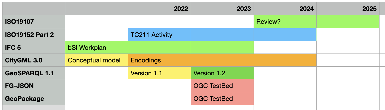
ISO 19107 - Geographic Information - Spatial Schemas
This work was last reviewed in 2019 and readopted - no changes were recommended or made. An important recommendation is the development of a profile suitable to the needs of the 3D CSDM. Whether such work would necesitate a revision of ISO19107 is unknown. We advise to keep in close contact with this ISO working group to ensure alignment.
LADM - ISO19152 (and LandInfra)
The second edition, currently under development, should extend the functionality of the LADM. This edition will have several parts and FIG could be involved in the development of parts:
-
Fundamentals – with possible involvement of Commission 3 (with Standards Australia in the lead);
-
Land Registration – with possible involvement of Commission 7;
-
Marine Space – with possible involvement of Commission 4 (with IHO in the lead);
-
Valuation Information – with possible involvement of Commission 9 (with RICS);
-
Spatial Plan Information – with possible involvement of Commission 8.
-
Implementation – with possible involvement of Commission 3 (with OGC in the lead)
Parts 2 and 6 are most closely related to 3D CSDM needs. Closely aligned with this work is the OGC LandInfra DWG, which oversees the LandInfra conceptual model and the InfraGML encodings. OGC and TC 211 commonly align calendars for related work. Members of each participate in both SDOs. This is unlikely to be an exception.
IFC 5
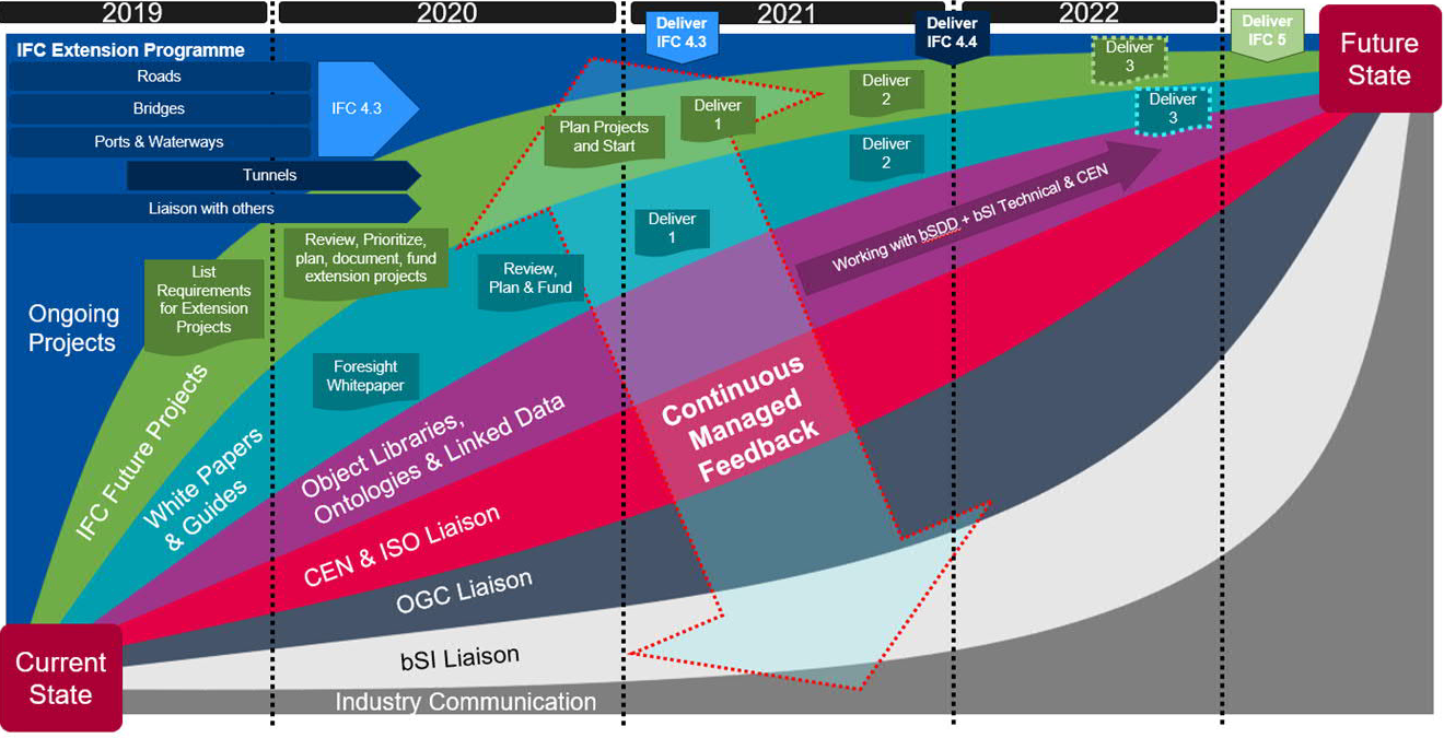
Building Smart International has initiated work on IFC 5. This revision could offer improvements that could significantly improve this standard’s compatibility with the requirements of the 3D CSDM. In addition, the proposed modular design should simplify incorporation of IFC into 3D CSDM systems. Therefore, participation is warranted to ensure a good outcome.
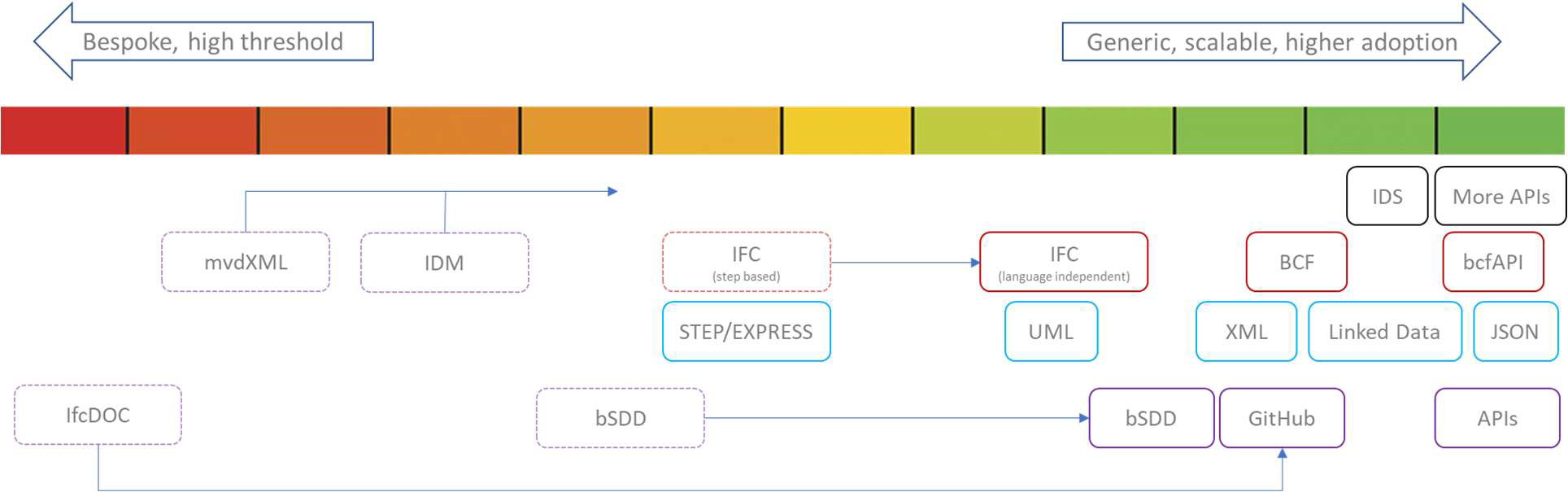
CityGML 3.0
The conceptual model for CityGML 3.0 has been published, and candidate encodings exist as XML and JSON. With this revision alignment with IFC, support for Smart Cities and Digital Twin applications is enhanced. Questions about incorporating cadastral data have yet to be asked let alone answered. Participation in the OGC CityGML (and CityJSON) SWGs is advised.
GeoSPARQL
OGC has recently finalised GeoSPARQL 1.1 content which will soon be released for vendor review, with a likely vote in March or April 2022.
Immediately after the GeoSPARQL SWG will begin work on version 1.2. This work is expected to take about a year. The 3D modelling requirements of the 3D CSDM will be raised as feature requests of 1.2. The outcomes are going to be one of:
-
Version 1.2 is released including the 3D features
-
Version 1.2 is released excluding the 3D features — 3D features are deferred to a future release
-
the SWG decides to undertake a comprehensive rebuilding of GeoSPARQL, perhaps "OGC Spatial Ontology" or similar — include the 3D elements but this might take longer than a year to make as it likely include lots of other things
We belive the first option to be most likely.
The current scopes of 1.1 (closed) and 1.2 are available at (https://github.com/opengeospatial/ogc-geosparql/projects). Version 1.2 scope currently includes several 3D issues. (https://github.com/opengeospatial/ogc-geosparql/issues/20)
One additional driver for 1.2 is to achieve dual OGC/ISO recognition. However, this may limit the number of new features in GeoSPARQL 1.2.
OGC Testbeds
We advise participation in other OGC standards development through SWGs and DWGs and testbed activities. Testbed activities are multi-participant efforts with many sponsors and participants working to solve defined problems. These occur annually. Sponsorship of an activity to progress the 3D CSDM requirements FG-JSON, CityJSON, InfraGML, GeoSPARQL and GeoPackage is advised.
Annex D: 3D Topology Profile of ISO19107
GML mechanisms
Whilst it is not expected that full implementations of GML topology are supported in available software, using GML as a baseline tests the underlying ISO19107 conceptual basis and helps identify the required profile of ISO19107 for the purposes of a 3D-cadastre.
A full scene example is provided in [TODO].
This section provides examples of the mechanisms for GML Topology and Geometry Integration.
Taking the requirement for an expression of the topological relationship between two features, let us examine how this is supported by GML.
We can see in the example below that a gml:Face provides the orientable surface that allows the solids on either side to be identified using a gml:directedTopoSolid property with orientation information.
<geo3:BoundaryFace>
<geo3:FaceGeometry>
<gml:Polygon gml:id="blue_yellow_bottom">
<gml:exterior>
<gml:LinearRing gml:id="lr5">
<gml:pointProperty xlink:href="#p11"/>
...
<gml:pointProperty xlink:href="#p11"/>
</gml:LinearRing>
</gml:exterior>
</gml:Polygon>
</geo3:faceGeometry>
<geo3:topoFace>
<gml:Face gml:id="f5">
<gml:directedEdge orientation="+" xlink:href="#e19"/>
...
<gml:directedEdge orientation="-" xlink:href="#e17"/>
<gml:directedTopoSolid orientation="+" xlink:href="#s1"/>
<gml:directedTopoSolid orientation="-" xlink:href="#s2"/>
</gml:Face>
</geo3:topoFace>
</geo3:BoundaryFace>The referenced solid "s1" is actually a member of a CompositeSolid "cs1", which is ultimate linked to the feature "cp1" (Blue spatial unit)
<icsm:CadastralParcel gml:id="cp1">
<gml:name>Blue spatial unit</gml:name>
<icsm:spatialExtent>
<gml:CompositeSolid gml:id="cs1">
<gml:solidMember>
<gml:Solid gml:id="s1">
<gml:name>Blue box above ground</gml:name>
<gml:exterior>
<gml:Shell>
<gml:surfaceMember xlink:href="#blue_top"/>
<gml:surfaceMember xlink:href="#blue_front_above_ground"/>
...
<gml:surfaceMember xlink:href="#blue_yellow_front"/>
</gml:Shell>
</gml:exterior>
</gml:Solid>
<gml:topoSolid gml:id="ts1">
<gml:directedFace orientation="+" xlink:ref="#f1"/>
...
<gml:directedFace orientation="+" xlink:ref="#f5"/>
...
<gml:directedFace orientation="+" xlink:ref="#f16"/>
</gml:topoSolid>
</gml:solidMember>Individual topology elements are linked via nodes to the point geometries of SurveyPoints….
<icsm:BoundaryVector gml:id="bv19">
<geo3:geometry>
<geo3:CurveGeometry>
<gml:LineString gml:id="ls19">
<gml:pointProperty xlink:href="#p11"/>
<gml:pointProperty xlink:href="#p20"/>
</gml:LineString>
</geo3:CurveGeometry>
</geo3:geometry>
<geo3:edge>
<gml:Edge gml:id="e19">
<gml:directedNode orientation="-" xlink:href="#n11"/>
...
<gml:directedFace orientation="-" xlink:href="#blue_yellow_rear"/>
</gml:Edge>
</geo3:edge>
</icsm:BoundaryVector>
<icsm:3dSurveyPoint gml:id="p11">
<gml:pointProperty>
<gml:Point gml:id="g_p11" srsName="*XY-MT*" srsDimension="3">
<gml:pos>-33.717 43.089 2.530</gml:pos>
</gml:Point>
</gml:pointProperty>
<geo3:Node>
<gml:Node gml:id="n_p11" gml:pointProperty xlink:href="#g_p11">
<gml:directedEdge gml:edgeProperty orientation="-" xlink:href="#e16"/>
<gml:directedEdge gml:edgeProperty orientation="+" xlink:href="#e19"/>
<gml:directedEdge gml:edgeProperty orientation="+" xlink:href="#e17"/>
<gml:directedEdge gml:edgeProperty orientation="+" xlink:href="#e38"/>
</gml:Node>
</geo3:Node>
</icsm:3dSurveyPoint>This approach is extremely powerful in that Features exist for each element that participates in topology relationships, a general model for topology based on orientation of edges can be expressed and the ultimate position is expressed once against a SurveyPoint concept.
It is however extremely complex and requires significant effort to build solid geometry objects for visualisation.
This exercise is thus regarded as a confirmation of the power of ISO19107 and the expressivity of GML, however it also suggests need for a simpler logical model tuned to the basic requirements of 3D topology.
OWL and SHACL models
An equivalent OWL model for the GML profile above is under development. Early drafts are present in the "Geometry Primitives" Conformance Class however:
-
this will be factored out as a candidate extension got GeoSPARQL1.2 under the existing GeoSPARQL namespace
-
methods to simplify topology statements are being explored.
RDF as JSON-LD
The RDF version (i.e. the canonical logical model ) for the same topology information can be implemented using a more familiar JSON encoding, linked to the model using JSON-LD.
This is a simple as adding a context document reference to a JSON object, however different logical models will use different schemas for the JSON.
An example of enabling JSON-LD with the GeoJSON logical model can be found at https://geojson.org/geojson-ld/
@prefix ex: <http://example.org/> .
@prefix geo: <http://www.opengis.net/ont/geosparql#> .
@prefix owl: <http://www.w3.org/2002/07/owl#> .
@prefix rdf: <http://www.w3.org/1999/02/22-rdf-syntax-ns#> .
@prefix rdfs: <http://www.w3.org/2000/01/rdf-schema#> .
@prefix geojson: <https://purl.org/geojson/vocab#> .
@prefix xsd: <http://www.w3.org/2001/XMLSchema#> .
ex:example1
a geo:Feature ;
ex:name "Dinagat Islands" ;
geo:hasGeometry [
a "Point" ;
geojson:coordinates (
1.256E2
1.01E1
) ;
] ;
.maps to JSON-LD equivalent (for display convenience with a in-line context document )
{
"@context": {
"ex": "http://example.org/",
"geo": "http://www.opengis.net/ont/geosparql#",
"rdf": "http://www.w3.org/1999/02/22-rdf-syntax-ns#",
"type": "rdf:type",
"geometry": "geo:hasGeometry",
"name": "ex:name",
"coordinates": {
"@container": "@list",
"coordinates": "geojson:coordinates"
}
},
@id "ex:example_1"
"type": "Feature",
"geometry": {
"type": "Point",
"coordinates": [125.6, 10.1]
},
"name": "Dinagat Islands"This is an example for illustrative purposes - an activity to standardise the RDF as a GeoSPARQL extension is proposed.
Note there are two choices available for an extended profile, based on the chosen logical model for implementation:
-
a direct mapping from RDF canonical logical model based on GeoSPARL 1.2 to an equivalent JSON schema
-
an indirect mapping (requiring mapping rules and software support) to map to a specific JSON schema such as GeoJSON 1.0
The optimum solution would be to provide a a canonical JSON schema that is isomorphic to GeoSPARQL 1.2 (with topology and Solid Geometry support) and evolve this into GeoJSON 2.0 with native JSON-LD support. In the interim a GeoSPARQL-JSON scheme would have the same status as the many different alternative JSON schemas (geoJSON, cityJSON, topoJSON etc). Making these modular and interoperable is beyond the scope of the ICSM Conceptual Model for 3D Cadastral Survey Dataset Submissions but could be developed and demonstrated alongside integration with IFC via ifcOWL and ifcJSON.
Annex E: Extended Examples
This annex provides complete "scene" examples used to derive test examples for individual concepts. Note that these are part of an evaluation exercise regarding the potential implementation capability of GML and the general applicability of the underlying ISO19107 model.
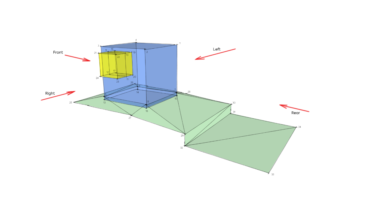
3D Geometry and Topology (GML)
This is not a proposal for a standardised data exchange format
<?xml version="1.0" encoding="UTF-8"?>
<icsm:CSDM xmlns:icsm="https://www.example.org/gml/icsm"
xmlns:geo3="https://www.example.org/geo3"
xmlns:xsi="http://www.w3.org/2001/XMLSchema-instance"
xmlns:xlink="http://www.w3.org/1999/xlink"
xmlns:gml="https://www.opengis.net/gml/3.2"
xsi:schemaLocation="https://www.example.org/gml/icsm 3dcsdm.xsd">
<gml:boundedBy>
<gml:Envelope srsName="*XY-MT*" srsDimension="3">
<gml:lowerCorner>20.82 -44.15 -1.85</gml:lowerCorner>
<gml:upperCorner>89.88 -20.5 5.0</gml:upperCorner>
</gml:Envelope>
</gml:boundedBy>
<gml:description>
This example consists of two cadastral units (Estates) being a Blue Box and a Yellow Box, a surface parcel (also an Estate), a ground surface (a type of occupation feature), survey points (cadastral marks, boundary marks, and geodetic reference marks), survey observations (traverse, side shots, occupation, and adopted), boundary lines, computed lines, and occupation features. The Yellow box is encased partially into the Blue Box. The Blue Box extends through the ground surface. The Blue Box is described by a GML Composite Solid consisting of two GML Solids, one representing the portion of the Blue Box that is above ground, and the other being that portion below ground. The Yellow Box is also a composite solid consisting of a solid that describes the portion of the Yellow Box that is encased by the Blue Box and a solid describing the portion of the Yellow Box that is outside the Blue Box. The two cadastral units touch at five common faces, being the interface between the Blue Box and the Yellow Box. The touch relationship is described in the topology - the respective faces identify a composite solid on either side, whereas other faces only identify a composite solid on the inside of the face. The ground surface is represented by a GML surface member. The intersection of the ground surface with the Blue Box is described by a Ground Intersection curve, a curve. The occupation features, a retaining wall, two wodden fences, and two privet hedges are defined as curves representing the centreline of the feature defined by observations to occupation marks. The occupation features are not defined in 3D, but could be (by offset/extrusion of the occupation feature curve).
</gml:description>
<icsm:observableFeature>The full GML file can be downloaded for review here .
3D Geometry and Topology (IFC)
|
Note
|
IFC Topology
This example shows an IFC encoded version of the same example scene using the following structural hierarchy:
.Simple IFC Hierarchy
* IFCProject
IFCSite
* IFCBuilding
* IFCBuildingStory
IFCSpace … (the IFCSpace class can be used to define a Cadastral parcel in 2D and 3D)
*
IFCBuildingElement … (there are many different Building
Element classes that can be used to describe building occupations - e.g.
walls, floors, roofs, etc…)
|
Blue Box Geometry (GML)
<gml:CompositeSolid gml:id="cs1">
<gml:solidMember>
<gml:Solid gml:id="s1">
<gml:name>Blue Box above Ground</gml:name>
<gml:description>dim( I(Blue Box) ∩ E(Yellow Box) = 2), ST_Disjoint</gml:description>
<gml:exterior>
<gml:Shell>
<gml:surfaceMember xlink:href="#blue_top"/>
<gml:surfaceMember xlink:href="#blue_front_above_ground"/>
<gml:surfaceMember xlink:href="#blue_right_above_ground"/>
<gml:surfaceMember xlink:href="#blue_rear_above_ground"/>
<gml:surfaceMember xlink:href="#blue_left_above_ground"/>
<gml:surfaceMember xlink:href="#blue_bottom_ground"/>
<gml:surfaceMember xlink:href="#blue_yellow_bottom"/>
<gml:surfaceMember xlink:href="#blue_yellow_left"/>
<gml:surfaceMember xlink:href="#blue_yellow_rear"/>
<gml:surfaceMember xlink:href="#blue_yellow_top"/>
<gml:surfaceMember xlink:href="#blue_yellow_front"/>
</gml:Shell>
</gml:exterior>
</gml:Solid>
<gml:Solid gml:id="s2">
<gml:name>Blue Box below Ground</gml:name>
<gml:description>Blue box below ground surface</gml:description>
<gml:exterior>
<gml:Shell>
<gml:surfaceMember>
<gml:OrientableSurface orientation="-">
<gml:baseSurface xlink:href="#blue_bottom_ground"/>
</gml:OrientableSurface>
</gml:surfaceMember>
<gml:surfaceMember xlink:href="#blue_right_below_ground"/>
<gml:surfaceMember xlink:href="#blue_rear_below_ground"/>
<gml:surfaceMember xlink:href="#blue_left_below_ground"/>
<gml:surfaceMember xlink:href="#blue_front_below_ground"/>
<gml:surfaceMember xlink:href="#blue_bottom_below_ground"/>
</gml:Shell>
</gml:exterior>
</gml:Solid>
</gml:solidMember>
</gml:CompositeSolid>Blue Box Geometry (CityGML)
<gml:CompositeSolid gml:id="cs1">
<gml:solidMember>
<gml:Solid gml:id="s1">
<gml:name>Blue Box above Ground</gml:name>
<gml:description>dim( I(Blue Box) ∩ E(Yellow Box) = 2), ST_Disjoint</gml:description>
<gml:exterior>
<gml:Shell>
<gml:surfaceMember xlink:href="#blue_top"/>
<gml:surfaceMember xlink:href="#blue_front_above_ground"/>
<gml:surfaceMember xlink:href="#blue_right_above_ground"/>
<gml:surfaceMember xlink:href="#blue_rear_above_ground"/>
<gml:surfaceMember xlink:href="#blue_left_above_ground"/>
<gml:surfaceMember xlink:href="#blue_bottom_ground"/>
<gml:surfaceMember xlink:href="#blue_yellow_bottom"/>
<gml:surfaceMember xlink:href="#blue_yellow_left"/>
<gml:surfaceMember xlink:href="#blue_yellow_rear"/>
<gml:surfaceMember xlink:href="#blue_yellow_top"/>
<gml:surfaceMember xlink:href="#blue_yellow_front"/>
</gml:Shell>
</gml:exterior>
</gml:Solid>
<gml:Solid gml:id="s2">
<gml:name>Blue Box below Ground</gml:name>
<gml:description>Blue box below ground surface</gml:description>
<gml:exterior>
<gml:Shell>
<gml:surfaceMember>
<gml:OrientableSurface orientation="-">
<gml:baseSurface xlink:href="#blue_bottom_ground"/>
</gml:OrientableSurface>
</gml:surfaceMember>
<gml:surfaceMember xlink:href="#blue_right_below_ground"/>
<gml:surfaceMember xlink:href="#blue_rear_below_ground"/>
<gml:surfaceMember xlink:href="#blue_left_below_ground"/>
<gml:surfaceMember xlink:href="#blue_front_below_ground"/>
<gml:surfaceMember xlink:href="#blue_bottom_below_ground"/>
</gml:Shell>
</gml:exterior>
</gml:Solid>
</gml:solidMember>
</gml:CompositeSolid>Blue Box Topology (GML)
<gml:topoSolid gml:id="ts1">
<gml:directedFace orientation="+" xlink:ref="#f1"/>
<gml:directedFace orientation="+" xlink:ref="#f2"/>
<gml:directedFace orientation="+" xlink:ref="#f4"/>
<gml:directedFace orientation="+" xlink:ref="#f8"/>
<gml:directedFace orientation="+" xlink:ref="#f14"/>
<gml:directedFace orientation="+" xlink:ref="#f5"/>
<gml:directedFace orientation="+" xlink:ref="#f6"/>
<gml:directedFace orientation="+" xlink:ref="#f7"/>
<gml:directedFace orientation="+" xlink:ref="#f10"/>
<gml:directedFace orientation="+" xlink:ref="#f11"/>
<gml:directedFace orientation="+" xlink:ref="#f16"/>
</gml:topoSolid>
<gml:topoSolid gml:id="ts2">
<gml:directedFace orientation="-" xlink:ref="#f16"/>
<gml:directedFace orientation="+" xlink:ref="#f9"/>
<gml:directedFace orientation="+" xlink:ref="#f12"/>
<gml:directedFace orientation="+" xlink:ref="#f15"/>
<gml:directedFace orientation="+" xlink:ref="#f3"/>
<gml:directedFace orientation="+" xlink:ref="#f13"/>
</gml:topoSolid>Survey Observations (GML)
Traverse Observation
<icsm:traverseObservation gml:id="ts1" equipmentUsed="001">
<gml:LineString gml:id="tls1">
<gml:pointProperty xlink:href="#t1"/>
<gml:pointProperty xlink:href="#t2"/>
</gml:LineString>
<icsm:observedVector>
<azimuth>335.01666667</azimuth>
<zenithAngle>95.45000000</zenithAngle>
<slopeDistance>17.055</slopeDistance>
</icsm:observedVector>
<icsm:vectorQuality>
<angularAccuracy>0.00277778</angularAccuracy>
<distanceAccuracy>0.006</distanceAccuracy>
</icsm:vectorQuality>
</icsm:traverseObservation>Side Observation
<icsm:sideObservation gml:id="ss2" equipmentUsed="001">
<gml:LineString gml:id="ssls2">
<gml:pointProperty xlink:href="#t1"/>
<gml:pointProperty xlink:href="#p5"/>
</gml:LineString>
<icsm:observedVector>
<azimuth>281.61666667</azimuth>
<zenithAngle>88.91666667</zenithAngle>
<slopeDistance>7.352</slopeDistance>
</icsm:observedVector>
<icsm:vectorQuality>
<angularAccuracy>0.06563086659</angularAccuracy>
<distanceAccuracy>0.020</distanceAccuracy>
</icsm:vectorQuality>
</icsm:sideObservation>Adopted Observation
<icsm:adoptedObservation gml:id="ad1" equipmentUsed="002">
<gml:LineString gml:id="adls1">
<gml:pointProperty xlink:href="#a1"/>
<gml:pointProperty xlink:href="#p26"/>
</gml:LineString>
<icsm:adoptedVector>
<azimuth>42.0833333333</azimuth>
<horizDistance>5.89</horizDistance>
<source>DP 333333</source>
</icsm:adoptedVector>
</icsm:adoptedObservation>Bibliography
- [ISO13249]
- International Organization for Standardization/International Electrotechnical Commission 13249-3 ISO/IEC 13249-3: Information technology — Database languages — SQL multimedia and application packages — Part 3: Spatial (2000)
- [ISO19105]
- International Organization for Standardization, ISO 19105: Geographic information – Conformance and testing (2000)
- [ISO19107]
- International Organization for Standardization, ISO 19107: Geographic information — Spatial schema (2003)